EP1586876A1 - Pfeife und pfeifemeldungsgerät - Google Patents
Pfeife und pfeifemeldungsgerät Download PDFInfo
- Publication number
- EP1586876A1 EP1586876A1 EP04703467A EP04703467A EP1586876A1 EP 1586876 A1 EP1586876 A1 EP 1586876A1 EP 04703467 A EP04703467 A EP 04703467A EP 04703467 A EP04703467 A EP 04703467A EP 1586876 A1 EP1586876 A1 EP 1586876A1
- Authority
- EP
- European Patent Office
- Prior art keywords
- whistle
- section
- information
- rolling element
- illumination
- Prior art date
- Legal status (The legal status is an assumption and is not a legal conclusion. Google has not performed a legal analysis and makes no representation as to the accuracy of the status listed.)
- Withdrawn
Links
Images


Classifications
-
- G—PHYSICS
- G10—MUSICAL INSTRUMENTS; ACOUSTICS
- G10K—SOUND-PRODUCING DEVICES; METHODS OR DEVICES FOR PROTECTING AGAINST, OR FOR DAMPING, NOISE OR OTHER ACOUSTIC WAVES IN GENERAL; ACOUSTICS NOT OTHERWISE PROVIDED FOR
- G10K5/00—Whistles
Definitions
- the present invention relates to a whistle used as a signal in sports and so forth, and a whistle signaling apparatus.
- a whistle has traditionally been used as a signal for the start and end of a game, and rule infringements, in various kinds of sports such as volleyball, rugby, and soccer.
- a conventional whistle is known that is composed of a mouthpiece, a resonant chamber containing a rolling element made of cork or the like, and an airflow aperture.
- This object can be achieved by notifying a hearing-impaired person that a whistle has been blown by converting the sound of a whistle to the form of an indication that can be recognized visually.
- FIG.1 is a drawing showing the configuration of a whistle system according to Embodiment 1 of the present invention.
- a whistle system is equipped with a whistle 1 and a lamp apparatus 2 that is a separate entity fromwhistle 1 and that receives whistle information transmitted by whistle 1 and gives an illuminated indication.
- Whistle 1 is equipped with a mouthpiece 3, a resonant chamber 5 containing a rolling element 4 made of cork or the like, a sensor 6 that detects movement of rolling element 4, and a transmitting apparatus 7 that transmits whistle information.
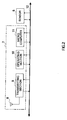
- FIG.2 is a block diagram showing the electrical configuration of whistle 1.
- transmitting section 7 is equipped with an antenna 8, a transmitting section 9, an operating section 10, and a microcomputer 11. Each section of transmitting apparatus 7 and sensor 6 are connected via a bus line 12. Microcomputer 11 controls each section of transmitting apparatus 7, and therefore has a CPU, ROM that stores a program for operating the CPU, and RAM used in CPU operations (not shown). Operating section 10 is used to perform whistle 1 operations by means of a power supply on/off switch and so forth.
- Transmitting section 9 transmits whistle information generated by microcomputer 11 based on sensor 6 output, using a carrier of a predetermined frequency.
- Sensor 6 detects vibration of rolling element 4 using a piezoelectric element, for example, and its output signal is taken in by microcomputer 11.
- Microcomputer 11 determines how the whistle was blown (strongly or weakly) based on the sensor 6 output signal level and variation of the output signal level over time, and generates whistle information to which the result of this determination is added. That is to say, when the whistle is blown strongly, whistle information is generated to which a determination result indicating that the whistle was blown strongly is added, and when the whistle is blown weakly, whistle information is generated to which a determination result indicating that the whistle was blown weakly is added.
- Whistle information generated by microcomputer 11 is input to transmitting section 9, and is transmitted by means of a carrier of a predetermined frequency.
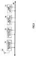
- FIG.3, is a block diagram showing the electrical configuration of lamp apparatus 2.
- lamp apparatus 2 is equipped with an antenna 13, a receiving section 14 that demodulates whistle information from a radio signal captured by antenna 13 and outputs that information, an operating section 15 for operating this apparatus 2, a microcomputer 16 that controls each section of this apparatus 2, a lamp section 17 equipped with a lamp such as an incandescent lamp or a light emitting diode lamp, and a bus line 18 that interconnects receiving section 14, operating section 15, microcomputer 16, and lamp section 17.
- Operating section 15 is used to perform apparatus 2 operations such as power supply on/off switch operations.
- microcomputer 16 has a CPU, ROM that stores a program for operating the CPU, and RAM used in CPU operations (not shown) .
- Microcomputer 16 determines the intensity of the sound of a whistle from information to which whistle information has been added, obtained from receiving section 14, generates an illumination signal according to the result of that determination, and inputs this illumination signal to lamp section 17.
- Lamp section 17 illuminates the lamp in accordance with the illumination signal from microcomputer 16.
- microcomputer 11 makes the interval at which the lamp is illuminated shorter when the whistle has been blown strongly, and makes the interval at which the lamp is illuminated longer when the whistle has been blown weakly. By this means, a player can visually recognize that the whistle has been blown, and also ascertain the intensity of the sound of the whistle.
- FIG. 4 shows an example of the use of lamp apparatuses 2 in soccer, in which it is assumed that lamp apparatuses 2 are placed on the surface of the ground. In a sport such as soccer that uses a large playing area, it is appropriate to use at least six lamp apparatuses 2 so that players can notice the flashing of lamp apparatuses 2 from any direction.
- a lamp apparatus 2 is placed at the left and right corners at each end of the pitch, and at each end of the halfway line.
- the radio signal transmitted from whistle 1 is transmitted by receiving section 14 of lamp apparatus 2, and the whistle information is demodulated.
- the demodulated whistle information is input to microcomputer 16, and the intensity of the sound of the whistle is determined.
- illumination control of lamp section 17 is performed in accordance with the whistle sound intensity determination result. That is to say, the lamp is illuminated at shorter intervals when the whistle has been blown strongly, and is illuminated at longer intervals when the whistle has been blown weakly.
- whistle 1 generates and transmits whistle information when blown
- lamp apparatus 2 receives a radio signal transmitted from whistle 1, demodulates the whistle information, and illuminates a lamp in accordance with the intensity of the sound of the whistle based on the whistle information, thereby enabling the fact that the whistle has been blown, and the strength with which it has been blown, to be ascertained.
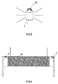
- FIG.5 is a block diagram showing an external view of a lamp apparatus of a whistle system according to Embodiment 2 of the present invention.
- a rack 20 is attached to lamp apparatus 2. Attaching rack 20 allows lamp apparatuses 2 to be hung on a net used in volleyball, tennis, badminton, table tennis, and so forth.
- FIG.6 shows an example in which lamp apparatuses 2 are hung on the wire from which a volleyball net 30 is suspended. Suspending lamp apparatuses 2 enables the fact that a whistle has been blown to be ascertained without looking directly at the referee.
- a rack 20 is attached to lamp apparatus 2, allowing lamp apparatus 2 to be suspended from a net or the like, thereby enabling the fact that a whistle has been blown to be ascertained while looking toward one's opponents.
- rack 20 is attached to the top of lamp apparatus 2, but rack 20 may also be attached to the side or the bottom. It is also possible to use a fastening device other than rack 20, such as a belt or hook-and-loop fastener.
- FIG.7 is a drawing showing the configuration of a whistle system according to Embodiment 3 of the present invention.
- a whistle system has a function that enables the kind of whistle information that is to be transmitted to be set, making possible adjacent use of identical whistle systems. As it often happens in tournaments that matches are played on a number of adjacent courts, the blowing of a whistle might cause a lamp apparatus installed on an adjacent court to be illuminated.
- the kind of whistle information is coordinated between a whistle and a lamp apparatus constituting one set so that a lamp apparatus installed on an adjacent court will not be illuminated.
- a whistle 40 is equipped with a switch 41 that sets the kind of whistle information, and the kind of whistle information transmitted is changed by manipulating this switch 41.
- a lamp apparatus 42 is equipped with a switch 43 that selects the kind of whistle information to be received, and the kind of whistle information received is changed by manipulating this switch 43. Setting the same kind of whistle information between a whistle 40 and lamp apparatus 42 forming a pair prevents that lamp apparatus 42 from being operated by whistle information transmitted from a whistle 40 of another set.
- Whistle 40 of this embodiment has a similar configuration to whistle 1 of Embodiment 1 shown in FIG.2, but has switch 41 provided on operating section 10. Whistle 40 will now be described with reference to FIG.2.
- microcomputer 11 of whistle 40 When generating whistle information, microcomputer 11 of whistle 40 reads the set value of switch 41, and generates a kind of whistle information corresponding to that set value. In this case, the result of determination that determines the intensity of the sound of the whistle is added. The generated whistle information is input to transmitting section 9 and transmitted.
- Lamp apparatus 42 has a similar configuration to lamp apparatus 2 of a whistle system according to Embodiment 1 shown in FIG.3. Lamp apparatus 42 will now be described with reference to FIG.3.
- microcomputer 16 reads the set value of switch 43, determines whether or not the input whistle information matches the kind of whistle information corresponding to that set value, and discards that whistle information if the set value does not match, or performs lamp section 17 illumination control if the set value matches.
- whistle 40 transmits whistle information of the kind set with switch 41, and lamp apparatus 42 compares received whistle information with the set value of switch 43, and illuminates the lamp only if they match, as a result of which identical whistle systems can be used next to each other in a normal manner without interference.
- interference between adjacent whistle systems is prevented by changing the kind of whistle information, but it is also possible to add unique identification information to whistle information, or to change the frequency.
- FIG. 8 is a drawing showing a whistle of a whistle system according to Embodiment 4 of the present invention.
- a whistle of this embodiment has a function that enables transmission output to be adjusted.
- a whistle 50 of this embodiment is equipped with a sliding adjustor (such as a variable resistor, for example) 51, and when this adjustor 51 is manipulated, transmission output adjustment data corresponding to the amount of manipulation is input to microcomputer 11 (see FIG.2).
- microcomputer 11 takes in transmission output adjustment data, it performs transmitting section 9 gain adjustment so that the transmission output corresponds to that data. Specifically, gain adjustment is performed for a variable gain amplifier provided on the input side of the power amplifier comprising transmitting section 9.
- FIG. 9 is a drawing showing transmission output range PA in the case of use on a tennis court 60
- FIG.10 is a drawing showing the transmission output range in the case of use on a soccer pitch 70.
- tennis court 60 when a lamp apparatus 2 is placed at either side of the center line, the transmission output is adjusted to a range that includes these two lamp apparatuses as shown in FIG. 9.
- soccer pitch 70 when a lamp apparatus 2 is placed at the left and right corners at each end of the pitch, and at each end of the halfway line, the transmission output is adjusted to a range that includes these lamp apparatuses as shown in FIG.10.
- a whistle 50 is provided that enables the transmission output to be adjusted, making it possible to set the transmission output according to the size of the playing area, and so enabling unnecessary power consumption to be suppressed, and making longer use possible as a result of the lower power consumption.
- a piezoelectric element is used as sensor 6, but a photosensor or a photosensor and a light emitting device, for example, may also be used.
- the detecting surface of the sensor is positioned facing the airflow aperture of the body of the whistle.
- a whistle can be provided that enables a hearing-impaired person to be aware that a whistle has been blown, and to concentrate on playing without anxiety.
- the present invention is suitable for use in a whistle used as a signal in sports and so forth, and a whistle signaling apparatus.
Landscapes
- Physics & Mathematics (AREA)
- Engineering & Computer Science (AREA)
- Acoustics & Sound (AREA)
- Multimedia (AREA)
- Audible And Visible Signals (AREA)
- Toys (AREA)
- Telephone Set Structure (AREA)
Applications Claiming Priority (3)
| Application Number | Priority Date | Filing Date | Title |
|---|---|---|---|
| JP2003011998A JP2004264324A (ja) | 2003-01-21 | 2003-01-21 | ホイッスル |
| JP2003011998 | 2003-01-21 | ||
| PCT/JP2004/000396 WO2004065922A1 (ja) | 2003-01-21 | 2004-01-20 | ホイッスル及びホイッスル報知装置 |
Publications (2)
| Publication Number | Publication Date |
|---|---|
| EP1586876A1 true EP1586876A1 (de) | 2005-10-19 |
| EP1586876A4 EP1586876A4 (de) | 2006-02-01 |
Family
ID=32767305
Family Applications (1)
| Application Number | Title | Priority Date | Filing Date |
|---|---|---|---|
| EP04703467A Withdrawn EP1586876A4 (de) | 2003-01-21 | 2004-01-20 | Pfeife und pfeifemeldungsgerät |
Country Status (5)
| Country | Link |
|---|---|
| US (1) | US20060180073A1 (de) |
| EP (1) | EP1586876A4 (de) |
| JP (1) | JP2004264324A (de) |
| CN (1) | CN1739009A (de) |
| WO (1) | WO2004065922A1 (de) |
Cited By (3)
| Publication number | Priority date | Publication date | Assignee | Title |
|---|---|---|---|---|
| GB2447265A (en) * | 2007-03-05 | 2008-09-10 | Chris Skelton | A signalling system to assist hard-of-hearing sports people |
| WO2013011259A1 (en) * | 2011-07-18 | 2013-01-24 | Leonard Maxwell | Alerting system |
| EP3178531A1 (de) * | 2015-12-10 | 2017-06-14 | INGLOT Mardcin F.H.U. IngTrans | Verfahren zur fernsteuerung eines lichtsignalsystems im laufe von sportspielen, die von spielern mit sprach- oder hörbehinderungen gespielt werden, und ein satz elektronischer vorrichtungen zur anwendung des verfahrens |
Families Citing this family (18)
| Publication number | Priority date | Publication date | Assignee | Title |
|---|---|---|---|---|
| KR200446468Y1 (ko) * | 2007-12-11 | 2009-10-30 | 김의겸 | Led를 이용한 청각장애인용 출발 신호기 |
| US8866599B2 (en) * | 2008-10-24 | 2014-10-21 | International Business Machines Corporation | Method of activating a supplemental visual warning signal based on frequency emitted from a generator of a primary audible warning signal |
| CN103177716A (zh) * | 2011-12-22 | 2013-06-26 | 海洋王照明科技股份有限公司 | 便携式灯具 |
| US9940918B2 (en) * | 2012-03-21 | 2018-04-10 | Thoroughbred Kids Llc | Toot suite whistle pack |
| US11501746B2 (en) | 2012-03-21 | 2022-11-15 | Thoroughbred Kids, LLC | Toot suite whistle pack |
| US20150124568A1 (en) * | 2013-11-01 | 2015-05-07 | Peter Paul Royer | Digital Whistle |
| US9610491B2 (en) | 2014-07-11 | 2017-04-04 | ProSports Technologies, LLC | Playbook processor |
| US9502018B2 (en) | 2014-07-11 | 2016-11-22 | ProSports Technologies, LLC | Whistle play stopper |
| US9305441B1 (en) | 2014-07-11 | 2016-04-05 | ProSports Technologies, LLC | Sensor experience shirt |
| US9398213B1 (en) | 2014-07-11 | 2016-07-19 | ProSports Technologies, LLC | Smart field goal detector |
| US9474933B1 (en) | 2014-07-11 | 2016-10-25 | ProSports Technologies, LLC | Professional workout simulator |
| US9724588B1 (en) | 2014-07-11 | 2017-08-08 | ProSports Technologies, LLC | Player hit system |
| US10264175B2 (en) | 2014-09-09 | 2019-04-16 | ProSports Technologies, LLC | Facial recognition for event venue cameras |
| TWM506353U (zh) * | 2015-04-21 | 2015-08-01 | Astrotek Integration Co Ltd | 具有氣壓感測元件之哨子 |
| CN105107199B (zh) * | 2015-07-31 | 2019-04-30 | 李菁 | 体育运动遥控提示系统及其装置和方法 |
| US10262524B2 (en) * | 2016-09-23 | 2019-04-16 | Paul A Guido | Personal security whistle apparatus |
| CN116801762A (zh) * | 2021-02-05 | 2023-09-22 | Ykk株式会社 | 带安装器具 |
| US11450183B1 (en) * | 2021-06-24 | 2022-09-20 | Michael Williams | Sports headgear signaling system |
Family Cites Families (7)
| Publication number | Priority date | Publication date | Assignee | Title |
|---|---|---|---|---|
| US4314316A (en) * | 1980-04-21 | 1982-02-02 | Leona Gertler | Illuminating whistle |
| US5002006A (en) * | 1990-07-20 | 1991-03-26 | Ehrenreich Harriet K | Combined safety whistle with article holding means |
| US5515808A (en) * | 1994-07-07 | 1996-05-14 | Edlund; Gary | Alerting mechanism for a whistle |
| US5507246A (en) * | 1994-11-07 | 1996-04-16 | Rand, Jr.; David | Visible signaling sports whistle |
| JP3965225B2 (ja) * | 1996-08-06 | 2007-08-29 | 松下 賢庸 | 救命用検知システムおよび救命用発信装置 |
| US6181236B1 (en) * | 1999-12-04 | 2001-01-30 | Arnold C. Schneider, Jr. | Sports whistle with audible and visual output signals |
| JP2002352684A (ja) * | 2001-05-25 | 2002-12-06 | Toybox:Kk | 通電方法及び電源スイッチ機構及びそれを用いた玩具 |
-
2003
- 2003-01-21 JP JP2003011998A patent/JP2004264324A/ja active Pending
-
2004
- 2004-01-20 WO PCT/JP2004/000396 patent/WO2004065922A1/ja not_active Ceased
- 2004-01-20 EP EP04703467A patent/EP1586876A4/de not_active Withdrawn
- 2004-01-20 CN CNA2004800021977A patent/CN1739009A/zh active Pending
- 2004-01-20 US US10/542,610 patent/US20060180073A1/en not_active Abandoned
Cited By (6)
| Publication number | Priority date | Publication date | Assignee | Title |
|---|---|---|---|---|
| GB2447265A (en) * | 2007-03-05 | 2008-09-10 | Chris Skelton | A signalling system to assist hard-of-hearing sports people |
| WO2013011259A1 (en) * | 2011-07-18 | 2013-01-24 | Leonard Maxwell | Alerting system |
| EP3178531A1 (de) * | 2015-12-10 | 2017-06-14 | INGLOT Mardcin F.H.U. IngTrans | Verfahren zur fernsteuerung eines lichtsignalsystems im laufe von sportspielen, die von spielern mit sprach- oder hörbehinderungen gespielt werden, und ein satz elektronischer vorrichtungen zur anwendung des verfahrens |
| WO2017097408A1 (en) | 2015-12-10 | 2017-06-15 | Marcin Inglot | A method of remote controlling a luminous signalling system in the course of sports games played by orally and aurally challenged players and a set of electronic devices for application of the method |
| US10235847B2 (en) | 2015-12-10 | 2019-03-19 | INGLOT Maran F.H.U. IngTrans | Method of remote controlling a luminous signalling system in the course of sports games played by orally and aurally challenged players and a set of electronic devices for application of the method |
| RU2720959C2 (ru) * | 2015-12-10 | 2020-05-15 | ИНГЛОТ Марцин Ф.Х.У. ИнгТранс | Способ дистанционного управления светосигнальной системой в ходе спортивных игр, в которые играют игроки с нарушениями речи и слуха, и набор электронных устройств для применения способа |
Also Published As
| Publication number | Publication date |
|---|---|
| CN1739009A (zh) | 2006-02-22 |
| WO2004065922A1 (ja) | 2004-08-05 |
| JP2004264324A (ja) | 2004-09-24 |
| EP1586876A4 (de) | 2006-02-01 |
| US20060180073A1 (en) | 2006-08-17 |
Similar Documents
| Publication | Publication Date | Title |
|---|---|---|
| EP1586876A1 (de) | Pfeife und pfeifemeldungsgerät | |
| US10169964B2 (en) | Method of activating a supplemental visual warning signal based on frequency emitted from a generator of a primary audible warning signal | |
| US7905782B2 (en) | Game apparatus having general-purpose remote control function | |
| US20210308550A1 (en) | Lighting apparatus for bag toss game | |
| US5553860A (en) | Sports impact sensor apparatus for proximate operation | |
| US5324038A (en) | Golfer's monitoring system | |
| US5300921A (en) | Athletic training system | |
| US6181236B1 (en) | Sports whistle with audible and visual output signals | |
| US10235847B2 (en) | Method of remote controlling a luminous signalling system in the course of sports games played by orally and aurally challenged players and a set of electronic devices for application of the method | |
| US20070105664A1 (en) | Racquet with Entertainment and Performance Feedback | |
| WO1999009368A1 (en) | Electronic game with infrared emitter and sensor | |
| US20020068556A1 (en) | Remote control | |
| CA2248745A1 (en) | Wireless game control units | |
| HK1024824A2 (en) | Hide and find toy game | |
| US20110130230A1 (en) | Ball for use in play and/or training | |
| CA3040405C (en) | Infrared hockey puck and goal detection system | |
| DE59502181D1 (de) | Vorrichtung zur verhinderung von manipulationen an tischspielgeräten | |
| KR200206958Y1 (ko) | 원격 조정되는 경기장용 전광 스톱워치 장치 | |
| JP2006149850A (ja) | タイム計測システム及びゴール検出システム | |
| TR2022006064A2 (tr) | Spor hakem düdüğünde yüksek ses si̇stemi̇ | |
| GB2278703A (en) | A signalling device | |
| JPH10290493A (ja) | 声量検出装置 | |
| SE9800631L (sv) | Kommunikationssystem för matcher | |
| JP2006095141A (ja) | パチンコ・パチスロ用不正電波探知方法及びパチンコ・パチスロ用不正電波探知装置 | |
| KR19990004040U (ko) | 퍼팅 연습 장치 |
Legal Events
| Date | Code | Title | Description |
|---|---|---|---|
| PUAI | Public reference made under article 153(3) epc to a published international application that has entered the european phase |
Free format text: ORIGINAL CODE: 0009012 |
|
| 17P | Request for examination filed |
Effective date: 20050715 |
|
| AK | Designated contracting states |
Kind code of ref document: A1 Designated state(s): AT BE BG CH CY CZ DE DK EE ES FI FR GB GR HU IE IT LI LU MC NL PT RO SE SI SK TR |
|
| AX | Request for extension of the european patent |
Extension state: AL LT LV MK |
|
| A4 | Supplementary search report drawn up and despatched |
Effective date: 20051216 |
|
| RIC1 | Information provided on ipc code assigned before grant |
Ipc: G10K 5/00 20060101AFI20051212BHEP |
|
| DAX | Request for extension of the european patent (deleted) | ||
| RBV | Designated contracting states (corrected) |
Designated state(s): DE FR GB |
|
| RIN1 | Information on inventor provided before grant (corrected) |
Inventor name: NAKAMOTO, KENJIC/O MATSUSHITA EL. IND. CO., INC. |
|
| STAA | Information on the status of an ep patent application or granted ep patent |
Free format text: STATUS: THE APPLICATION HAS BEEN WITHDRAWN |
|
| 18W | Application withdrawn |
Effective date: 20070606 |