EP1586882A2 - Appareil et procédé de détermination de cliquetis pour moteur à combustion interne - Google Patents
Appareil et procédé de détermination de cliquetis pour moteur à combustion interne Download PDFInfo
- Publication number
- EP1586882A2 EP1586882A2 EP05008325A EP05008325A EP1586882A2 EP 1586882 A2 EP1586882 A2 EP 1586882A2 EP 05008325 A EP05008325 A EP 05008325A EP 05008325 A EP05008325 A EP 05008325A EP 1586882 A2 EP1586882 A2 EP 1586882A2
- Authority
- EP
- European Patent Office
- Prior art keywords
- knock
- distribution
- waveform
- sensor
- engine
- Prior art date
- Legal status (The legal status is an assumption and is not a legal conclusion. Google has not performed a legal analysis and makes no representation as to the accuracy of the status listed.)
- Granted
Links
Images


Classifications
-
- G—PHYSICS
- G01—MEASURING; TESTING
- G01L—MEASURING FORCE, STRESS, TORQUE, WORK, MECHANICAL POWER, MECHANICAL EFFICIENCY, OR FLUID PRESSURE
- G01L23/00—Devices or apparatus for measuring or indicating or recording rapid changes, such as oscillations, in the pressure of steam, gas, or liquid; Indicators for determining work or energy of steam, internal-combustion, or other fluid-pressure engines from the condition of the working fluid
- G01L23/22—Devices or apparatus for measuring or indicating or recording rapid changes, such as oscillations, in the pressure of steam, gas, or liquid; Indicators for determining work or energy of steam, internal-combustion, or other fluid-pressure engines from the condition of the working fluid for detecting or indicating knocks in internal-combustion engines; Units comprising pressure-sensitive members combined with ignitors for firing internal-combustion engines
- G01L23/221—Devices or apparatus for measuring or indicating or recording rapid changes, such as oscillations, in the pressure of steam, gas, or liquid; Indicators for determining work or energy of steam, internal-combustion, or other fluid-pressure engines from the condition of the working fluid for detecting or indicating knocks in internal-combustion engines; Units comprising pressure-sensitive members combined with ignitors for firing internal-combustion engines for detecting or indicating knocks in internal combustion engines
- G01L23/225—Devices or apparatus for measuring or indicating or recording rapid changes, such as oscillations, in the pressure of steam, gas, or liquid; Indicators for determining work or energy of steam, internal-combustion, or other fluid-pressure engines from the condition of the working fluid for detecting or indicating knocks in internal-combustion engines; Units comprising pressure-sensitive members combined with ignitors for firing internal-combustion engines for detecting or indicating knocks in internal combustion engines circuit arrangements therefor
Definitions
- the present invention relates to an apparatus and a method for determining occurrence of a knock in an internal combustion engine.
- a knock determining apparatus of a typical internal combustion engine includes a knock sensor attached to the cylinder block of the internal combustion engine.
- the knock sensor detects vibration of the cylinder block caused by a knock.
- the determining apparatus extracts the knock frequency component from an output signal of the knock sensor by a bandpass filter and compares a peak value of the knock frequency component or an integral of the knock frequency component during a predetermined interval with a knock determination threshold value to perform knock determination.
- a knock is prevented by retarding the ignition timing, but retarding the ignition timing deteriorates the engine output and the fuel economy. Therefore, it is required to advance the ignition timing within a range of knock noise tolerable to the human ear and improve the engine output and the fuel economy. Therefore, the knock determination threshold value needs to be adapted to a value that permits detecting only a knock exceeding the permissible level to the human ear.
- Japanese Examined Patent Publication No. 6-60621 discloses an apparatus that corrects the knock determination threshold value such that the distribution of a value obtained by the logarithmic conversion of the peak value of an output signal of the knock sensor will have a predetermined profile.
- the distribution profile is formed that is similar to the profile made when a knock occurs. This deteriorates the correction accuracy of the knock determination threshold value, thereby deteriorating the knock determination accuracy.
- a knock determining apparatus for an internal combustion engine includes a sensor, distribution determining means, and knock state determining means.
- the sensor outputs a signal that has a waveform corresponding to the knock state of the internal combustion engine.
- the distribution determining means obtains variables representing the characteristics of a knock from an output signal of the sensor every time the engine is ignited.
- the distribution determining means obtains a distribution of the variables corresponding to a predetermined number of times of ignition.
- the knock state determining means determines the occurrence of a knock based on whether the profile of the distribution obtained by the distribution determining means has the characteristics that appear at the occurrence of a knock.
- variables representing the characteristics of a knock are obtained from an output signal of the sensor, and a distribution of the variables corresponding to a predetermined number of times of ignition is obtained. Therefore, unlike the distribution of only the peak value of the sensor output as that created in the publication No. 6-60621, a distribution that distinguishes noise from a knock is created. Therefore, deterioration of knock determination accuracy due to noise is solved, thereby improving the accuracy and the reliability of knock determination.
- the variables preferably include a peak value of the knock frequency component in the output signal of the sensor and a waveform correlation coefficient representing the correlation between the waveform of the output signal and an ideal knock waveform, which is the waveform specific to a knock.
- the waveform correlation coefficient distinguishes noise from a knock with high accuracy.
- the vibration of the cylinder block and the fluctuation of the combustion pressure vary by a relatively large amount in accordance with the operating condition of the internal combustion engine. Therefore, when creating the distribution directly from the output signal of the sensor, the distribution profile varies in accordance with the engine operating condition. Thus, when creating the distribution directly from the output signal of the sensor, the distribution needs to be created for each engine operating condition.
- the data values of the variables corresponding to a predetermined number of times of ignition are preferably normalized (equated, made dimensionless) using the mean and the standard deviation of each variable and the distribution of the normalized data values of the variables is obtained.
- a universal distribution is created that has no differences due to the operating condition of the engine, and the distribution need not be created per each engine operating condition. This reduces the processing load of producing a distribution and prevents deterioration of the accuracy of the distribution due to changes of the engine operating condition.
- the mean and the standard deviation are not updated until a predetermined amount of data values are stored. Therefore, the mean and the standard deviation may be approximately obtained by filtering the variables. In this case, since the memory capacity is saved, and the mean and the standard deviation are updated every time the variable is obtained, fast response is achieved.
- all the regions in which the detection distribution possibly exists may be subdivided into smaller regions, and a counter may be provided in each region. However, in this case, the number of the counters becomes excessive and excessive amount of the memory is used.
- Regions in which the characteristics of a knock become significant are extracted from regions in which the distribution possibly exists, each characteristic region is provided with a counter, and the counter of the characteristic region to which the variables belong is incremented at every ignition to obtain the distribution.
- the counters of only the few characteristic regions in which the characteristics of a knock become significant are incremented. This considerably saves the amount of the memory used. Furthermore, since only the portions in which the characteristics of a knock become significant are selected and extracted, the accuracy and the reliability of knock determination are sufficiently secured.
- the distribution of the variables corresponding to the predetermined number of times of ignition when a knock exceeding a permissible level is occurring is stored as an ideal knock distribution in storage means.
- the correlation between the distribution obtained by the distribution determination means and the ideal knock distribution is obtained while the engine is running. It is determined that the knock level is greater (frequency of occurrence of knocks is higher) as the correlation is increased. In this case, the knock level is accurately determined.
- the knock level (frequency of occurrence of knocks) is determined based on the distribution obtained by the distribution determination means.
- the knock level is compared with a predetermined knock determination threshold value to determine the existence of a knock.
- the knock determination threshold value is corrected in accordance with the comparison result between the knock level and the knock determination threshold. In this case, even if a mechanical or electrical noise overlaps the output signal of the sensor, the knock determination threshold value is accurately corrected. This prevents decrease of the knock determination accuracy due to noise.
- the knock determination threshold value is automatically corrected in accordance with the production variation of the engine and changes of vibration level with time. Therefore, high precision knock determination is performed always using the appropriate knock determination threshold value.
- a design and development engineer need not to closely consider the influence of the production variation of the engine and deterioration with time when adapting the knock determination threshold value to the engine. This simplifies a process for adapting the knock determination threshold value to the engine.
- a knock sensor which detects the vibration of the cylinder block of the engine
- a combustion pressure sensor which detects the combustion pressure of the engine
- an ion current sensor which detects the ion current in the combustion chamber of the engine
- a knock occurs when an air-fuel mixture in a cylinder of the engine causes autoignition to be rapidly combusted without waiting for the flame propagation caused by the ignition of an ignition plug.
- the rapid combustion of the air-fuel mixture caused by autoignition vibrates combustion gas in the cylinder and fluctuates the combustion pressure and the ion generated during the combustion.
- Such vibration and fluctuation are transmitted to the cylinder block and generate a knocking sound (rattling sound) audible to the outside. Therefore, the vibration waveform specific to a knock is detected using any of the knock sensor, the combustion pressure sensor, and the ion current sensor.
- the present invention also provides a knock determining method for an internal combustion engine.
- the method includes: outputting a signal that has a waveform corresponding to the knock state of the internal combustion engine from a sensor; obtaining variables representing the characteristics of a knock from an output signal of the sensor every time the engine is ignited; obtaining a distribution of the variables corresponding to a predetermined number of times of ignition; and determining the occurrence of a knock based on whether the profile of the obtained distribution has the characteristics that appear at the occurrence of a knock.
- An internal combustion engine which is an engine 11 in this embodiment, has an intake pipe 12. At the most upstream section of the intake pipe 12, an air cleaner 13 is provided. An air flow meter 14, which detects the intake air amount, is provided downstream of the air cleaner 13. A throttle valve 15, the opening degree of which is adjusted by a motor 10, and a throttle opening sensor 16, which detects the throttle opening degree, are located downstream of the air flow meter 14.
- the intake manifold 19 extends from the surge tank 17 to intake ports of the cylinders while being branched.
- Ignition plugs 21 each corresponding to one of the cylinders are attached to the cylinder head of the engine 11. Spark discharge of each ignition plug 21 ignites the air-fuel mixture in the corresponding cylinder.
- a catalyst 23 such as a three-way catalyst that removes CO, HC, NOx, or the like from emission gas are provided in an exhaust pipe 22 of the engine 11, and an air-fuel ratio sensor 24, which detects the air-fuel ratio of emission gas, is located upstream of the catalyst 23.
- a coolant temperature sensor 25, which detects the coolant temperature, a knock sensor 28, which detects the knock vibration, and a crank angle sensor 26, which outputs a pulse signal every time a crankshaft of the engine 11 rotates by a predetermined crank angle, are attached to a cylinder block of the engine 11. Based on the output signal of the crank angle sensor 26, the crank angle and the engine speed are detected.
- the output of the various types of sensors are supplied to an engine control unit (hereinafter, referred to as ECU) 27.
- the ECU 27 is mainly composed of a microcomputer and controls the fuel injection amount of the fuel injection valve 20 and the ignition timing of the ignition plug 21 by executing various types of engine control programs stored in an incorporated ROM (storing media).
- the ECU 27 obtains two variables (a peak value and a waveform correlation coefficient) representing the characteristics of a knock from the output of the knock sensor 28 (hereinafter, simply referred to as the sensor output) at every ignition by executing routines for knock determination in Figs. 2 to 5, which will be described later.
- the ECU 27 normalizes (equates, makes dimensionless) the data values of the two variables corresponding to a predetermined number of times of ignition and obtains the distribution of the normalized data values of the two variables.
- the ECU 27 calculates the correlation coefficient (degree of similarity) for knock determination representing the correlation (similarity) between the distribution and an ideal knock distribution as an index representing the knock level (frequency of occurrence of knocks).
- the ECU 27 Based on the calculated correlation coefficient for knock determination, the ECU 27 corrects the knock determination threshold value used in knock determination made at every single combustion.
- the ECU 27 compares the product of the two variables (the peak value and the waveform correlation coefficient) with the knock determination threshold value at every single combustion and determines the presence or absence of a knock at every single combustion.
- the ECU 27 performs a knock control in which, the ECU 27 suppresses a knock by retarding the ignition timing when it is determined that a knock is present, and the ECU 27 advances the ignition timing when it is determined that a' knock continues to be absent. Accordingly, the ECU 27 improves the engine output and the fuel consumption by advancing the ignition timing within a range of knock noise tolerable to the human ear.
- Variables extracted from sensor output represent the characteristics of a knock.
- the peak value of the knock frequency component in the sensor output and the waveform correlation coefficient representing the correlation between the waveform of the sensor output and the ideal knock waveform, which is the waveform specific to a knock are used as the variables.
- the waveform correlation coefficient is computed in the following manner. At first, the knock waveform that shows the ideal profile during the period before and after the peak is set as the ideal knock waveform. If the increase rate of the sensor output waveform before the peak is steeper than that of the ideal knock waveform, the ideal knock waveform is simply added up to obtain the waveform area before the peak.
- the waveform area before the peak is obtained by adding a value obtained by correcting the ideal knock waveform to be decreased by a predetermined amount in accordance with the difference between the sensor output waveform and the ideal knock waveform.
- the waveform area after the peak is obtained by adding a value obtained by correcting the ideal knock waveform to be decreased in accordance with the difference between the sensor output waveform after the peak and the ideal knock waveform.
- the waveform area before the peak and the waveform area after the peak are summed to obtain the waveform area during a predetermined period from before the peak to after the peak.
- the waveform area divided by the area of the ideal knock waveform is regarded as the waveform correlation coefficient.
- Normalized waveform correlation coefficient (waveform correlation coefficient - mean of waveform correlation coefficient)/standard deviation of waveform correlation coefficient
- the mean and the standard deviation are approximately obtained by a filtering process (smoothing process).
- a sequential normalization process can be performed using the approximately and sequentially computed mean and the standard deviation without storing a lot of data values in the memory.
- all the regions in which the detection distribution possibly exists may be subdivided into smaller regions, and a counter may be provided in each region to create the detection distribution.
- the number of the counters becomes excessive and excessive amount of the memory of the ECU 27 is used.
- a few regions in which the characteristics of a knock become significant are extracted from the regions in which the detection distribution possibly exists. Then, a counter is provided in each characteristic region.
- the distribution of the normalized data values (Sp, Sc) is obtained by incrementing, at each ignition, the counter in the characteristic region to which the normalized data values (Sp, Sc) of the peak value Sp and the waveform correlation coefficient Sc belong.
- the normalized data values (Sp, Sc) in only the few characteristic regions in which the characteristics of a knock become significant is counted. This considerably saves the amount of the memory used. Furthermore, since only the portions in which the characteristics of a knock become significant are selected and extracted, the accuracy and the reliability of knock determination are sufficiently secured.
- the correlation coefficient (degree of similarity) for knock determination that represents the correlation (similarity) between the detection distribution of the normalized data values (Sp, Sc) and the ideal knock distribution is computed.
- the correlation coefficient for knock determination serves as an index for determining whether the profile of the detection distribution has the characteristics that appear at the occurrence of a knock.
- the ideal knock distribution is the distribution of the normalized data values (Sp, Sc) computed in advance using the above mentioned method when a knock exceeding a permissible level is occurring, and is stored in a nonvolatile memory (storage means or storage section) such as the ROM of the ECU 27.
- the correlation coefficient for knock determination is obtained by dividing the inner product of the pattern of the detection distribution and the pattern of the ideal knock distribution by the product of the norms.
- the division by the product of the norms causes the absolute value of the correlation coefficient for knock determination to constantly become less than or equal to one (-1 ⁇ correlation coefficient for knock determination ⁇ 1), and as the correlation between the detection distribution and the ideal knock distribution is increased, the correlation coefficient for knock determination approaches a value close to one. Therefore, the correlation coefficient for knock determination serves as an index representing the knock level (frequency of occurrence of knocks), and as the correlation coefficient for knock determination approaches a value close to one, the knock level is determined to be great (frequency of occurrence of knocks is high).
- the correlation coefficient for knock determination is compared with a predetermined knock determination threshold value. If the correlation coefficient for knock determination is greater than or equal to the knock determination threshold value, it is determined that a knock exceeding the permissible level is occurring. Thus, a knock determination threshold value used for knock determination at every single combustion is corrected to be decreased. Therefore, small knocks are detected.
- the knock determination threshold value is corrected to be increased to detect only greater knocks.
- the knock determination threshold value need not be corrected.
- the knock determination threshold value is automatically corrected in accordance with the production variation of the engine and changes of the vibration level with time. Therefore, high precision knock determination is performed always using the appropriate knock determination threshold value.
- a design and development engineer need not to closely consider the influence of the production variation of the engine and deterioration with time when adapting the knock determination threshold value to the engine. This simplifies a process for adapting the knock determination threshold value to the engine.
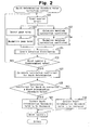
- the knock determination threshold value correction routine shown in Fig. 2 is executed periodically while the engine is running.
- the routine is started, at step S100, the ECU 27 increments a total counter that counts the number of samples of the variables (the peak value P and the waveform correlation coefficient C).
- the ECU 27 detects the peak value P of the knock frequency component in the sensor output at every ignition.
- the ECU 27 executes the waveform correlation coefficient calculating routine of Fig. 3 described later to calculate the waveform correlation coefficient C.
- step S103 the ECU 27 computes the mean and the standard deviation ⁇ of the peak value P using the smoothing process and normalizes (equates, make dimensionless) the peak value P using the mean and the standard deviation ⁇ .
- step S104 the ECU 27 executes the waveform correlation coefficient normalization routine of Fig. 5 described later. That is, the ECU 27 computes the mean and the standard deviation o of the waveform correlation coefficient C using the smoothing process and normalizes (equates, make dimensionless) the waveform correlation coefficient C using the mean and the standard deviation ⁇ .
- the ECU 27 proceeds to step S105 and executes the detection distribution creating routine (not shown) to create the detection distribution as described below.
- the detection distribution creating routine (not shown) to create the detection distribution as described below.
- few regions in which the characteristics of a knock become significant (characteristic regions) are extracted from the regions in which the detection distribution possibly exists.
- a counter is provided in each characteristic region.
- the ECU 27 determines whether the normalized data values (Sp, Sc) of the peak value P and the waveform correlation coefficient C correspond to any of the characteristic regions. If there is a corresponding characteristic region, the ECU 27 increments the counter of the appropriate characteristic region, and if there is no corresponding characteristic region, the ECU 27 does not increment the counter of the characteristic region.
- the ECU 27, which executes the above described process of steps S101 to S105 serves as distribution determining means or a distribution determining section.
- step S106 determines whether the value of the total counter has reached a predetermined value. If the value of the total counter has not reached the predetermined value, the ECU 27 repeats the process of steps S100 to S105. Therefore, until the number of samples of the peak value P and the waveform correlation coefficient C respectively reach the predetermined values, the ECU 27 repeats sampling of the peak value P and the waveform correlation coefficient C, normalization of the data values, and creating the detection distribution.
- the ECU 27 proceeds to step S107, and executes the correlation coefficient for knock determination calculating routine (not shown) to calculate the correlation coefficient for knock determination representing the correlation between the detection distribution based on the normalized data values (Sp, Sc) and the ideal knock distribution.
- the correlation coefficient for knock determination is obtained by dividing the inner product of the pattern of the detection distribution based on the normalized data values (Sp, Sc) and the pattern of the ideal knock distribution by the product of the norms.
- step S108 the ECU 27 proceeds to step S108, and compares the correlation coefficient for knock determination with the predetermined knock determination threshold value. If the correlation coefficient is greater than the knock determination threshold value, the ECU 27 determines that a knock exceeding the permissible level is occurring and proceeds to step S109. At step S109, the ECU 27 corrects the knock determination threshold value used for knock determination at every single combustion to be decreased. Therefore, small knocks are detected. Contrarily, if the correlation coefficient for knock determination is smaller than the knock determination threshold value, the ECU 27 determines that the knock level is below the permissible level. In this case, there is a possibility that the ignition timing is retarded more than necessary by the knock control, thereby decreasing the engine torque.
- step S110 the ECU 27 proceeds to step S110, and corrects the knock determination threshold value to be increased so that only greater knocks are detected. Thereafter, the ECU 27 proceeds to step S111, and resets all the counters used in this routine. Then, the ECU 27 ends the routine.
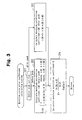
- the waveform correlation coefficient calculating routine of Fig. 3 is a subroutine executed in step S102 of the knock determination threshold value correction routine of Fig. 2.
- the ECU 27 detects the peak position of the waveform of the detected sensor output (hereinafter, referred to as detected waveform) (see Fig. 6).
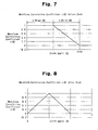
- the ECU 27 compares the detected waveform s[ ⁇ ] before the peak with the ideal knock waveform a[ ⁇ ], and calculates the waveform correlation coefficient c[ ⁇ ] before the peak as follows. That is, the ECU 27 determines whether the detected waveform s[ ⁇ ] at the crank angle ⁇ before the peak is less than or equal to the ideal knock waveform a[ ⁇ ]. If the detected waveform s[ ⁇ ] at the crank angle ⁇ before the peak is less than or equal to the ideal knock waveform a[ ⁇ ], the ECU 27 sets the waveform correlation coefficient c[ ⁇ ] before the peak at the crank angle ⁇ before the peak to "1".
- Fig. 7 shows a calculation example of the waveform correlation coefficient c[ ⁇ ] before the peak.
- the ECU 27 uses the detected waveform s[ ⁇ ] after the peak and the ideal knock waveform a[ ⁇ ] to calculate the waveform correlation coefficient c[ ⁇ ] after the peak at the crank angle ⁇ after the peak by the following equation.
- c[ ⁇ ] 1 -
- Fig. 8 shows a calculation example of the waveform correlation coefficient c[ ⁇ ] after the peak.
- the ECU 27 After repeating the process for calculating the waveform correlation coefficient c[ ⁇ ] for all the crank angle ⁇ during a predetermined period from before the peak to after the peak in the above described manner, the ECU 27 proceeds to step S204, and calculates the final waveform correlation coefficient C by the following equation.
- C ⁇ c[ ⁇ ] ⁇ a[ ⁇ ]/ ⁇ a[ ⁇ ]
- the waveform correlation coefficient C always becomes less than or equal to one (0 ⁇ C ⁇ 1), and as the correlation between the detected waveform s[ ⁇ ] and the ideal knock waveform a[ ⁇ ] is increased, the waveform correlation coefficient C approaches a value close to one.
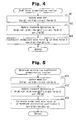
- the peak value normalization routine of Fig. 4 is a subroutine executed in step S103 of the knock determination threshold value correction routine of Fig. 2.
- the ECU 27 calculates the current mean Pav[n] of the peak value P[n] using the previously calculated mean Pav[n-1] of the peak value P stored in the RAM of the ECU 27 and the current peak value P[n] by the following equation of the smoothing process.
- Pav[n] ⁇ 1 ⁇ P[n] + (1- ⁇ 1) ⁇ Pav[n-1]
- ⁇ 1 represents a coefficient of smoothing.
- the smoothing coefficient ⁇ 1 may be fixed values to simplify the computation process.
- the smoothing coefficient ⁇ 1 may be changed in accordance with the engine operating state using a map, a mathematical expression, or the like. If this is the case, for example, during a normal operation of the engine, a setting that stresses the accuracy of the mean Pav is selected, and when the engine is in a transient operating state, a setting that stresses the trackability is selected. That is, the accuracy and the trackability are adjusted in accordance with the engine operating state.
- step S302 calculates the current variance Vp[n] of the peak value P using the previously calculated variance Vp[n-1] of the peak value P stored in the RAM of the ECU 27 and the current mean Pav[n] of the peak value P by the following smoothing process.
- Vp[n] ⁇ 1 ⁇ ⁇ P[n] - Pav[n] ⁇ 2 + (1 - ⁇ 1) ⁇ Vp[n-1]
- ⁇ 1 represents a coefficient of smoothing.
- the smoothing coefficient ⁇ 1 may be a fixed value to simplify the computation process.
- the smoothing coefficient ⁇ 1 may be changed in accordance with the engine operating state using a map, a mathematical expression, or the like. If this is the case, for example, during a normal operation of the engine, a setting that stresses the accuracy of the variance Vp is selected, and when the engine is in a transient operating state, a setting that stresses the trackability is selected. That is, the accuracy and the trackability are adjusted in accordance with the engine operating state.
- step S303 calculates the normalized data value Sp of the peak value P by the following equation.
- Sp ⁇ P[n] - Pav[n] ⁇ / ⁇ p
- the waveform correlation coefficient normalization routine of Fig. 5 is a subroutine executed in step S104 of the knock determination threshold value correction routine of Fig. 2.
- the ECU 27 calculates the current mean Cav[n] of the waveform correlation coefficient C[n] using the previously calculated mean Cav[n-1] of the waveform correlation coefficient C stored in the RAM of the ECU 27 and the current waveform correlation coefficient C[n] by the following equation of the smoothing process.
- Cav[n] ⁇ 2 ⁇ C[n] + (1- ⁇ 2) ⁇ Cav[n-1]
- ⁇ 2 represents a coefficient of smoothing.
- the smoothing coefficient ⁇ 2 may be fixed values to simplify the computation process.
- the smoothing coefficient ⁇ 2 may be changed in accordance with the engine operating state using a map, a mathematical expression, or the like. If this is the case, for example, during a normal operation of the engine, a setting that stresses the accuracy of the average value Cav is selected, and when the engine is in a transient operating state, a setting that stresses the trackability is selected. That is, the accuracy and the trackability are adjusted in accordance with the engine operating state.
- step S402 calculates the current variance Vc[n] of the waveform correlation coefficient C using the previously calculated variance V c[n-1] of the waveform correlation coefficient C stored in the RAM of the ECU 27 and the current mean Cav[n] of the waveform correlation coefficient C by the following equation of the smoothing process.
- ⁇ 2 represents a coefficient of smoothing.
- the smoothing coefficient ⁇ 2 may be a fixed value to simplify the computation process.
- the smoothing coefficient ⁇ 2 may be changed in accordance with the engine operating state using a map, a mathematical expression, or the like. If this is the case, for example, during a normal operation of the engine, a setting that stresses the accuracy of the variance Vc is selected, and when the engine is in a transient operating state, a setting that stresses the trackability is selected. That is, the accuracy and the trackability are adjusted in accordance with the engine operating state.
- the ECU 27 obtains the peak value of the knock frequency component in the sensor output and the waveform correlation coefficient representing the correlation between the waveform of the sensor output and the ideal knock waveform, which is the waveform specific to a knock.
- the ECU 27 then creates the distribution of the peak value and the waveform correlation coefficient corresponding to the predetermined number of times of ignition. Therefore, unlike the distribution that uses only the peak value of the sensor output as that created in the publication No. 6-60621, the ECU 27 creates a distribution that distinguishes noise from a knock. Therefore, the problem of deterioration of knock determination accuracy due to noise is solved, thereby improving the accuracy and the reliability of knock determination.
- the data values of the peak value and the waveform correlation coefficient corresponding to the predetermined number of times of ignition are respectively normalized using the corresponding mean and the corresponding standard deviation to create the detection distribution. Therefore, a universal detection distribution is created that has no differences due to the operating condition of the engine, and the detection distribution need not be created per each engine operating condition. This reduces the processing load of producing a distribution and prevents deterioration of the accuracy of the detection distribution due to changes of the engine operating condition.
- the correlation coefficient for the knock determination representing the correlation (similarity) between the detection distribution and the ideal knock distribution is calculated as the index of the knock level.
- the knock determination threshold value used for knock determination at every single combustion is corrected. Therefore, even if a mechanical or electrical noise overlaps the sensor output, the knock determination threshold value is accurately corrected. This prevents decrease of the knock determination accuracy due to noise.
- the knock determination threshold value is automatically corrected in accordance with the production variation of the engine and changes of vibration level with time. Therefore, high precision knock determination is performed always using the appropriate knock determination threshold value.
- a design and development engineer need not to closely consider the influence of the production variation of the engine and deterioration with time when adapting the knock determination threshold value to the engine. This simplifies a process for adapting the knock determination threshold value to the engine.
- the knock sensor 28 which detects the vibration of the cylinder block, is used as a sensor that outputs a signal having a waveform that corresponds to the knock state.
- a combustion pressure sensor which detects the combustion pressure
- an ion current sensor which detects the ion current in the combustion chamber, may be used.
Landscapes
- Chemical & Material Sciences (AREA)
- Engineering & Computer Science (AREA)
- Combustion & Propulsion (AREA)
- Physics & Mathematics (AREA)
- General Physics & Mathematics (AREA)
- Combined Controls Of Internal Combustion Engines (AREA)
- Ignition Installations For Internal Combustion Engines (AREA)
- Electrical Control Of Ignition Timing (AREA)
Applications Claiming Priority (2)
| Application Number | Priority Date | Filing Date | Title |
|---|---|---|---|
| JP2004121865A JP4390104B2 (ja) | 2004-04-16 | 2004-04-16 | 内燃機関のノック判定装置 |
| JP2004121865 | 2004-04-16 |
Publications (3)
| Publication Number | Publication Date |
|---|---|
| EP1586882A2 true EP1586882A2 (fr) | 2005-10-19 |
| EP1586882A3 EP1586882A3 (fr) | 2005-11-30 |
| EP1586882B1 EP1586882B1 (fr) | 2011-07-27 |
Family
ID=34935256
Family Applications (1)
| Application Number | Title | Priority Date | Filing Date |
|---|---|---|---|
| EP05008325A Expired - Lifetime EP1586882B1 (fr) | 2004-04-16 | 2005-04-15 | Appareil et procédé de détermination de cliquetis pour moteur à combustion interne |
Country Status (4)
| Country | Link |
|---|---|
| US (1) | US7043353B2 (fr) |
| EP (1) | EP1586882B1 (fr) |
| JP (1) | JP4390104B2 (fr) |
| CN (1) | CN100344950C (fr) |
Cited By (6)
| Publication number | Priority date | Publication date | Assignee | Title |
|---|---|---|---|---|
| WO2005103466A3 (fr) * | 2004-04-22 | 2006-03-09 | Toyota Motor Co Ltd | Dispositif de determination de cliquetis dans un moteur a combustion interne et systeme de commande d'allumage comportant un tel dispositif |
| WO2007080815A1 (fr) * | 2006-01-10 | 2007-07-19 | Toyota Jidosha Kabushiki Kaisha | Dispositif et procédé permettant de déterminer un cognement de moteur à combustion interne |
| WO2007142348A1 (fr) * | 2006-06-06 | 2007-12-13 | Toyota Jidosha Kabushiki Kaisha | Dispositif et procédé de détermination de cognement pour moteur à combustion interne |
| EP1959122A4 (fr) * | 2006-10-03 | 2010-01-13 | Toyota Motor Co Ltd | Dispositif de jugement du cognement du moteur à combustion interne et procédé de jugement du cognement |
| US7822533B2 (en) | 2006-05-29 | 2010-10-26 | Toyota Jidosha Kabushiki Kaisha | Knocking determination device and knocking determination method of internal combustion engine |
| EP2960476A4 (fr) * | 2013-02-19 | 2016-03-30 | Toyota Motor Co Ltd | Dispositif de détection de combustion anormale pour moteur à combustion interne |
Families Citing this family (41)
| Publication number | Priority date | Publication date | Assignee | Title |
|---|---|---|---|---|
| JP4538383B2 (ja) * | 2005-06-28 | 2010-09-08 | トヨタ自動車株式会社 | 内燃機関の点火時期制御装置 |
| JP4600181B2 (ja) * | 2005-06-28 | 2010-12-15 | トヨタ自動車株式会社 | 内燃機関の点火時期制御装置 |
| JP4459125B2 (ja) * | 2005-07-15 | 2010-04-28 | 株式会社デンソー | ノック発生状態判定装置 |
| JP4756968B2 (ja) * | 2005-09-16 | 2011-08-24 | 株式会社デンソー | 内燃機関のノック判定装置 |
| JP4342520B2 (ja) * | 2006-01-27 | 2009-10-14 | トヨタ自動車株式会社 | 内燃機関の点火時期制御装置 |
| JP4447576B2 (ja) * | 2006-05-29 | 2010-04-07 | トヨタ自動車株式会社 | 内燃機関のノッキング判定装置 |
| JP4221013B2 (ja) | 2006-06-16 | 2009-02-12 | トヨタ自動車株式会社 | 内燃機関の点火時期制御装置 |
| US7603226B2 (en) * | 2006-08-14 | 2009-10-13 | Henein Naeim A | Using ion current for in-cylinder NOx detection in diesel engines and their control |
| JP4686431B2 (ja) * | 2006-10-11 | 2011-05-25 | 日立オートモティブシステムズ株式会社 | 空燃比センサの劣化診断装置 |
| JP2008095602A (ja) * | 2006-10-12 | 2008-04-24 | Denso Corp | 内燃機関のノック判定装置 |
| JP4600431B2 (ja) | 2007-05-30 | 2010-12-15 | トヨタ自動車株式会社 | 内燃機関のノッキング判定装置 |
| JP4867826B2 (ja) * | 2007-07-11 | 2012-02-01 | トヨタ自動車株式会社 | 内燃機関のノッキング判定装置 |
| JP4949167B2 (ja) * | 2007-08-08 | 2012-06-06 | 株式会社デンソー | 内燃機関のノック判定装置 |
| JP4952554B2 (ja) * | 2007-12-06 | 2012-06-13 | トヨタ自動車株式会社 | 内燃機関の点火時期制御装置および点火時期制御方法 |
| US9157825B2 (en) * | 2008-05-01 | 2015-10-13 | GM Global Technology Operations LLC | Engine knock diagnostic |
| JP5198340B2 (ja) | 2009-03-31 | 2013-05-15 | 本田技研工業株式会社 | エンジンのノック制御装置 |
| JP5508834B2 (ja) * | 2009-12-22 | 2014-06-04 | 日産自動車株式会社 | 内燃機関のノック判定装置 |
| JP5645573B2 (ja) * | 2010-09-29 | 2014-12-24 | 三菱電機株式会社 | 内燃機関のノック制御装置 |
| JP5554199B2 (ja) * | 2010-10-04 | 2014-07-23 | 三菱電機株式会社 | 内燃機関のノック制御装置 |
| JP5762021B2 (ja) * | 2011-01-31 | 2015-08-12 | 三菱電機株式会社 | エンジンのノック制御装置 |
| CN102817761A (zh) * | 2011-06-10 | 2012-12-12 | 镇江润欣科技信息有限公司 | 一种抑制发动机爆震的方法 |
| JP5892786B2 (ja) * | 2011-12-26 | 2016-03-23 | 三菱電機株式会社 | 内燃機関のノック制御装置 |
| EP2820580A4 (fr) * | 2012-02-28 | 2015-07-29 | Univ Wayne State | Utilisation d'un signal de courant ionique pour performance de moteur et techniques de mesure d'émissions et procédés pour le réaliser |
| JP5395201B2 (ja) * | 2012-03-14 | 2014-01-22 | 三菱電機株式会社 | 内燃機関のノック制御装置 |
| JP5708543B2 (ja) * | 2012-03-28 | 2015-04-30 | トヨタ自動車株式会社 | 内燃機関の制御装置 |
| JP5546595B2 (ja) * | 2012-08-07 | 2014-07-09 | 三菱電機株式会社 | 内燃機関のノック制御装置 |
| US9523322B2 (en) * | 2012-12-14 | 2016-12-20 | Continental Automotive Systems, Inc. | Method to reduce engine combustion and harmonic noise for misfire detection |
| US9441556B2 (en) * | 2013-03-15 | 2016-09-13 | GM Global Technology Operations LLC | Noise updating systems and methods |
| JP6192594B2 (ja) * | 2014-05-27 | 2017-09-06 | 愛三工業株式会社 | グリルシャッタ装置 |
| JP6059194B2 (ja) | 2014-11-04 | 2017-01-11 | トヨタ自動車株式会社 | 内燃機関のノック判定装置 |
| CN106706205B (zh) * | 2015-07-24 | 2019-08-13 | 联合汽车电子有限公司 | 发动机爆震检测方法及发动机早燃检测方法 |
| CN106762133B (zh) * | 2016-11-28 | 2019-11-22 | 天津大学 | 一种基于震动的早燃和爆震检测系统及其检测方法 |
| CN106703991B (zh) * | 2016-12-05 | 2019-03-29 | 潍柴动力股份有限公司 | 一种发动机保护装置及方法 |
| JP7081421B2 (ja) * | 2018-09-19 | 2022-06-07 | 株式会社デンソー | ノック制御装置 |
| JP7081420B2 (ja) * | 2018-09-19 | 2022-06-07 | 株式会社デンソー | ノック判定装置及びノック制御装置 |
| JP6733795B1 (ja) * | 2019-09-24 | 2020-08-05 | トヨタ自動車株式会社 | 内燃機関の点火時期制御装置 |
| JP7133527B2 (ja) * | 2019-09-30 | 2022-09-08 | 本田技研工業株式会社 | スペクトル算出装置及びスペクトル算出方法 |
| DE102019131322B4 (de) * | 2019-11-20 | 2022-01-13 | Dr. Ing. H.C. F. Porsche Aktiengesellschaft | Verfahren und System zur Bestimmung der Motorbelastung über Lebenszeit durch Sensoranalyse |
| JP7397716B2 (ja) * | 2020-02-26 | 2023-12-13 | 株式会社デンソー | ノック判定装置及びノック制御装置 |
| CN112145299B (zh) * | 2020-09-04 | 2021-07-06 | 东风汽车集团有限公司 | 一种发动机防爆震干扰控制方法及存储介质 |
| CN115800287B (zh) * | 2022-10-27 | 2023-10-27 | 深圳市国电科技通信有限公司 | 一种基于阈值分割聚类的低压台区拓扑识别方法 |
Citations (1)
| Publication number | Priority date | Publication date | Assignee | Title |
|---|---|---|---|---|
| JPH0660621A (ja) | 1992-08-04 | 1994-03-04 | Matsushita Electric Ind Co Ltd | ビデオテープレコーダ |
Family Cites Families (11)
| Publication number | Priority date | Publication date | Assignee | Title |
|---|---|---|---|---|
| JPS5669532A (en) * | 1979-11-09 | 1981-06-10 | Nippon Soken Inc | Knocking detecting device |
| JPS6060621A (ja) | 1983-09-14 | 1985-04-08 | Toyo Denso Co Ltd | 光スイツチ装置 |
| US4800488A (en) * | 1985-11-12 | 1989-01-24 | American Telephone And Telegraph Company, At&T Bell Laboratories | Method of propagating resource information in a computer network |
| JP2730215B2 (ja) * | 1989-10-03 | 1998-03-25 | 株式会社デンソー | エンジン用ノック制御装置 |
| US5222242A (en) * | 1990-09-28 | 1993-06-22 | International Business Machines Corp. | System for locating a node containing a requested resource and for selectively verifying the presence of the resource at the node |
| JPH04252840A (ja) * | 1991-01-25 | 1992-09-08 | Nippondenso Co Ltd | 内燃機関用ノッキング制御装置 |
| US5526358A (en) * | 1994-08-19 | 1996-06-11 | Peerlogic, Inc. | Node management in scalable distributed computing enviroment |
| FR2765623B1 (fr) * | 1997-07-03 | 1999-09-10 | Renault | Dispositif de detection et de mesure de cliquetis et systeme anticliquetis comprenant un tel dispositif |
| DE19946346A1 (de) * | 1999-09-28 | 2001-03-29 | Bosch Gmbh Robert | Verfahren zur Klopferkennung |
| JP3711320B2 (ja) * | 1999-10-06 | 2005-11-02 | 三菱電機株式会社 | 内燃機関のノック制御装置 |
| JP3281624B2 (ja) * | 2000-02-25 | 2002-05-13 | ダイハツ工業株式会社 | イオン電流による内燃機関のノック検出方法 |
-
2004
- 2004-04-16 JP JP2004121865A patent/JP4390104B2/ja not_active Expired - Fee Related
-
2005
- 2005-04-15 EP EP05008325A patent/EP1586882B1/fr not_active Expired - Lifetime
- 2005-04-15 US US11/106,581 patent/US7043353B2/en not_active Expired - Lifetime
- 2005-04-15 CN CNB2005100646081A patent/CN100344950C/zh not_active Expired - Fee Related
Patent Citations (1)
| Publication number | Priority date | Publication date | Assignee | Title |
|---|---|---|---|---|
| JPH0660621A (ja) | 1992-08-04 | 1994-03-04 | Matsushita Electric Ind Co Ltd | ビデオテープレコーダ |
Cited By (12)
| Publication number | Priority date | Publication date | Assignee | Title |
|---|---|---|---|---|
| WO2005103466A3 (fr) * | 2004-04-22 | 2006-03-09 | Toyota Motor Co Ltd | Dispositif de determination de cliquetis dans un moteur a combustion interne et systeme de commande d'allumage comportant un tel dispositif |
| US7263430B2 (en) | 2004-04-22 | 2007-08-28 | Toyota Jidosha Kabushiki Kaisha | Internal combustion engine knock determination device and ignition control system including the same |
| WO2007080815A1 (fr) * | 2006-01-10 | 2007-07-19 | Toyota Jidosha Kabushiki Kaisha | Dispositif et procédé permettant de déterminer un cognement de moteur à combustion interne |
| KR100929994B1 (ko) * | 2006-01-10 | 2009-12-07 | 도요타 지도샤(주) | 내연기관의 노킹 판정 장치 및 방법 |
| US7779673B2 (en) | 2006-01-10 | 2010-08-24 | Toyota Jidosha Kabushiki Kaisha | Device and method for determining knocking of internal combustion engine |
| US7822533B2 (en) | 2006-05-29 | 2010-10-26 | Toyota Jidosha Kabushiki Kaisha | Knocking determination device and knocking determination method of internal combustion engine |
| DE112007001073B4 (de) * | 2006-05-29 | 2013-05-29 | Nippon Soken, Inc. | Klopfbestimmungsvorrichtung und Klopfbestimmungsverfahren einer Brennkraftmaschine |
| WO2007142348A1 (fr) * | 2006-06-06 | 2007-12-13 | Toyota Jidosha Kabushiki Kaisha | Dispositif et procédé de détermination de cognement pour moteur à combustion interne |
| US7945379B2 (en) | 2006-06-06 | 2011-05-17 | Toyota Jidosha Kabushiki Kaisha | Knock determination device and method for internal combustion engine |
| CN101467017B (zh) * | 2006-06-06 | 2011-08-31 | 丰田自动车株式会社 | 用于内燃机的爆震判定设备和方法 |
| EP1959122A4 (fr) * | 2006-10-03 | 2010-01-13 | Toyota Motor Co Ltd | Dispositif de jugement du cognement du moteur à combustion interne et procédé de jugement du cognement |
| EP2960476A4 (fr) * | 2013-02-19 | 2016-03-30 | Toyota Motor Co Ltd | Dispositif de détection de combustion anormale pour moteur à combustion interne |
Also Published As
| Publication number | Publication date |
|---|---|
| EP1586882A3 (fr) | 2005-11-30 |
| JP2005307753A (ja) | 2005-11-04 |
| CN100344950C (zh) | 2007-10-24 |
| US20050234633A1 (en) | 2005-10-20 |
| US7043353B2 (en) | 2006-05-09 |
| EP1586882B1 (fr) | 2011-07-27 |
| CN1683911A (zh) | 2005-10-19 |
| JP4390104B2 (ja) | 2009-12-24 |
Similar Documents
| Publication | Publication Date | Title |
|---|---|---|
| US7043353B2 (en) | Knock determining apparatus and method for internal combustion engine | |
| US7054735B2 (en) | Apparatus and method for controlling internal combustion engine | |
| CN101375051B (zh) | 用于在内燃机中通过爆震控制来控制点火正时的设备和方法 | |
| EP1924831B1 (fr) | Procede et dispositif permettant de determiner la presence d'un cliquetis pour des moteurs | |
| US6688286B2 (en) | Knock control apparatus for engine | |
| EP1672346B1 (fr) | Appareil pour détecter du cliquetis dans un moteur à combustion | |
| EP1959122B1 (fr) | Dispositif de jugement du cognement du moteur à combustion interne et procédé de jugement du cognement | |
| US5652380A (en) | Apparatus and method for detecting output fluctuations of an internal combustion engine, and apparatus and method for controlling the engine | |
| US8924134B2 (en) | Knock control device of internal combustion engine | |
| US6247448B1 (en) | Closed loop spark control method and system utilizing a combustion event sensor to determine borderline knock | |
| KR100929994B1 (ko) | 내연기관의 노킹 판정 장치 및 방법 | |
| US20100212634A1 (en) | Device and method for controlling ignition timing of internal combustion engine | |
| JP4925251B2 (ja) | 内燃機関のノック判定装置 | |
| JPH0392569A (ja) | 内燃機関のノッキング検出装置 | |
| JPH08151951A (ja) | 内燃機関のノッキング制御装置 | |
| JP4684066B2 (ja) | 内燃機関の点火時期制御装置 | |
| JPH04134159A (ja) | 内燃機関の制御装置 | |
| JP2004340104A (ja) | 振動検出センサの出力信号の補正方法、及び振動検出センサの出力信号の補正係数算出装置 | |
| JPH05202798A (ja) | 内燃機関用ノック制御装置 |
Legal Events
| Date | Code | Title | Description |
|---|---|---|---|
| PUAI | Public reference made under article 153(3) epc to a published international application that has entered the european phase |
Free format text: ORIGINAL CODE: 0009012 |
|
| PUAL | Search report despatched |
Free format text: ORIGINAL CODE: 0009013 |
|
| 17P | Request for examination filed |
Effective date: 20050415 |
|
| AK | Designated contracting states |
Kind code of ref document: A2 Designated state(s): AT BE BG CH CY CZ DE DK EE ES FI FR GB GR HU IE IS IT LI LT LU MC NL PL PT RO SE SI SK TR |
|
| AX | Request for extension of the european patent |
Extension state: AL BA HR LV MK YU |
|
| AK | Designated contracting states |
Kind code of ref document: A3 Designated state(s): AT BE BG CH CY CZ DE DK EE ES FI FR GB GR HU IE IS IT LI LT LU MC NL PL PT RO SE SI SK TR |
|
| AX | Request for extension of the european patent |
Extension state: AL BA HR LV MK YU |
|
| AKX | Designation fees paid |
Designated state(s): DE FR IT |
|
| 17Q | First examination report despatched |
Effective date: 20060804 |
|
| GRAP | Despatch of communication of intention to grant a patent |
Free format text: ORIGINAL CODE: EPIDOSNIGR1 |
|
| GRAS | Grant fee paid |
Free format text: ORIGINAL CODE: EPIDOSNIGR3 |
|
| GRAA | (expected) grant |
Free format text: ORIGINAL CODE: 0009210 |
|
| RTI1 | Title (correction) |
Free format text: KNOCK DETERMINING APPARATUS AND METHOD FOR INTERNAL COMBUSTION ENGINE |
|
| AK | Designated contracting states |
Kind code of ref document: B1 Designated state(s): DE FR IT |
|
| REG | Reference to a national code |
Ref country code: DE Ref legal event code: R096 Ref document number: 602005029143 Country of ref document: DE Effective date: 20110915 |
|
| PLBE | No opposition filed within time limit |
Free format text: ORIGINAL CODE: 0009261 |
|
| STAA | Information on the status of an ep patent application or granted ep patent |
Free format text: STATUS: NO OPPOSITION FILED WITHIN TIME LIMIT |
|
| 26N | No opposition filed |
Effective date: 20120502 |
|
| REG | Reference to a national code |
Ref country code: DE Ref legal event code: R097 Ref document number: 602005029143 Country of ref document: DE Effective date: 20120502 |
|
| REG | Reference to a national code |
Ref country code: DE Ref legal event code: R084 Ref document number: 602005029143 Country of ref document: DE Effective date: 20130125 |
|
| REG | Reference to a national code |
Ref country code: FR Ref legal event code: PLFP Year of fee payment: 12 |
|
| REG | Reference to a national code |
Ref country code: FR Ref legal event code: PLFP Year of fee payment: 13 |
|
| REG | Reference to a national code |
Ref country code: FR Ref legal event code: PLFP Year of fee payment: 14 |
|
| PGFP | Annual fee paid to national office [announced via postgrant information from national office to epo] |
Ref country code: FR Payment date: 20200312 Year of fee payment: 16 |
|
| PGFP | Annual fee paid to national office [announced via postgrant information from national office to epo] |
Ref country code: DE Payment date: 20200331 Year of fee payment: 16 |
|
| PGFP | Annual fee paid to national office [announced via postgrant information from national office to epo] |
Ref country code: IT Payment date: 20200312 Year of fee payment: 16 |
|
| REG | Reference to a national code |
Ref country code: DE Ref legal event code: R119 Ref document number: 602005029143 Country of ref document: DE |
|
| PG25 | Lapsed in a contracting state [announced via postgrant information from national office to epo] |
Ref country code: DE Free format text: LAPSE BECAUSE OF NON-PAYMENT OF DUE FEES Effective date: 20211103 Ref country code: FR Free format text: LAPSE BECAUSE OF NON-PAYMENT OF DUE FEES Effective date: 20210430 |
|
| PG25 | Lapsed in a contracting state [announced via postgrant information from national office to epo] |
Ref country code: IT Free format text: LAPSE BECAUSE OF NON-PAYMENT OF DUE FEES Effective date: 20200415 |
|
| PG25 | Lapsed in a contracting state [announced via postgrant information from national office to epo] |
Ref country code: IT Free format text: LAPSE BECAUSE OF NON-PAYMENT OF DUE FEES Effective date: 20210415 |