EP1586908B1 - Anschlussvorrichtung für einen Stromzähler - Google Patents
Anschlussvorrichtung für einen Stromzähler Download PDFInfo
- Publication number
- EP1586908B1 EP1586908B1 EP05007360A EP05007360A EP1586908B1 EP 1586908 B1 EP1586908 B1 EP 1586908B1 EP 05007360 A EP05007360 A EP 05007360A EP 05007360 A EP05007360 A EP 05007360A EP 1586908 B1 EP1586908 B1 EP 1586908B1
- Authority
- EP
- European Patent Office
- Prior art keywords
- contact
- connection apparatus
- connection
- electricity meter
- meter
- Prior art date
- Legal status (The legal status is an assumption and is not a legal conclusion. Google has not performed a legal analysis and makes no representation as to the accuracy of the status listed.)
- Expired - Lifetime
Links
- 230000005611 electricity Effects 0.000 title claims description 33
- 238000006073 displacement reaction Methods 0.000 claims description 25
- 239000004020 conductor Substances 0.000 claims description 16
- 239000000463 material Substances 0.000 claims description 4
- 238000003780 insertion Methods 0.000 claims description 3
- 230000037431 insertion Effects 0.000 claims description 3
- 239000002184 metal Substances 0.000 claims description 3
- 238000007599 discharging Methods 0.000 claims 2
- 238000002955 isolation Methods 0.000 claims 1
- 210000002414 leg Anatomy 0.000 description 37
- 238000002788 crimping Methods 0.000 description 2
- 238000007789 sealing Methods 0.000 description 2
- 238000003466 welding Methods 0.000 description 2
- TVEXGJYMHHTVKP-UHFFFAOYSA-N 6-oxabicyclo[3.2.1]oct-3-en-7-one Chemical compound C1C2C(=O)OC1C=CC2 TVEXGJYMHHTVKP-UHFFFAOYSA-N 0.000 description 1
- 238000005452 bending Methods 0.000 description 1
- 230000015572 biosynthetic process Effects 0.000 description 1
- 230000007423 decrease Effects 0.000 description 1
- 238000009413 insulation Methods 0.000 description 1
- 238000000034 method Methods 0.000 description 1
- 230000007935 neutral effect Effects 0.000 description 1
- 230000002093 peripheral effect Effects 0.000 description 1
- 238000004904 shortening Methods 0.000 description 1
- 210000000689 upper leg Anatomy 0.000 description 1
Images



Classifications
-
- G—PHYSICS
- G01—MEASURING; TESTING
- G01R—MEASURING ELECTRIC VARIABLES; MEASURING MAGNETIC VARIABLES
- G01R22/00—Arrangements for measuring time integral of electric power or current, e.g. electricity meters
- G01R22/06—Arrangements for measuring time integral of electric power or current, e.g. electricity meters by electronic methods
- G01R22/061—Details of electronic electricity meters
- G01R22/065—Details of electronic electricity meters related to mechanical aspects
-
- H—ELECTRICITY
- H01—ELECTRIC ELEMENTS
- H01R—ELECTRICALLY-CONDUCTIVE CONNECTIONS; STRUCTURAL ASSOCIATIONS OF A PLURALITY OF MUTUALLY-INSULATED ELECTRICAL CONNECTING ELEMENTS; COUPLING DEVICES; CURRENT COLLECTORS
- H01R31/00—Coupling parts supported only by co-operation with counterpart
- H01R31/06—Intermediate parts for linking two coupling parts, e.g. adapter
- H01R31/065—Intermediate parts for linking two coupling parts, e.g. adapter with built-in electric apparatus
Definitions
- the invention relates to a connection device for a power meter, which has a housing, projecting from its against a support plate ground through openings in the support plate passable contact elements according to at least one current phase, which by moving the guided on the support plate housing with stromzu- and -abblockden connection elements can be connected to the side facing away from the power meter side of the support plate, wherein the connection elements are bridged by a displaceable in the direction of displacement of the electricity meter guided part and the bridging part is displaceable when connecting the electricity meter by the electricity meter from a bridging position to an open position.
- connection device engages the contact element in a recess in the bridging part, so that the bridging member is taken on displacement of the counter and transferred to the open position, while the contact elements are connected to connecting conductors.
- a connecting device in which the bridging part is formed by spring contact elements with bent legs, which are in the bridging position in contact and are brought by displacement of the current meter by bending the legs through the contact elements of the electricity meter in the open position that no more contact between the thighs.
- the present invention has the object, a connection device of the type mentioned in such a way that a shortening of the length in the direction of displacement of the electricity meter is possible.
- the achieving this object device according to the invention is characterized in that and the bridging Obergurig part and are arranged offset at least one contact element perpendicularly to the displacement direction of the meter housing to each other and the bridging part is indirectly displaceable via an intermediate piece through the meter.
- the intermediate piece is preferably an opening for the contact elements having plate, with means for driving the bridging member.
- a further, movable transversely to the direction of displacement of the housing closure plate for closing passages leading to the connection elements through the openings in the plates may be formed, which is used when no electricity meter is connected to the counter place.
- the closure plate is sealable in the closed position.
- the stromzu- and -abveden connection elements perpendicular to the direction of displacement of the meter housing extending spring contact leg. Between these spring contact legs, the contact elements or the bridging part can be inserted laterally.
- connection elements allow short, from the power meter housing only over a small length projecting contact elements.
- one-piece contact pieces each with two mutually perpendicular to the direction of displacement of the meter housing offset pairs of spring contact legs are provided. At one of the spring contact leg pairs, the respective contact element is connected. The other pair of spring contact legs serves to make contact with the bridging part.
- a further spring leg may be provided on one of the pairs of spring legs, which forms a contact slot for a connection conductor with one of the two spring legs of the spring leg pair in question.
- the lateral insertion of the contact element or bridging part facilitating guiding devices are formed on the spring contact legs.
- projections are formed on the driver plate in the direction of displacement aligned with the openings for the contact elements, which isolate the connection elements against the contact elements before the contact is made or cover the connection elements, so that when the current counter is tilted onto the support plate no live parts are present exposed.
- a hooking on the support plate by the contact elements releasably entanglement can be provided, which prevents that the drive plate from the outside by a generally available tool, for. If the power meter is placed obliquely on the support plate, the drive plate advantageously remains in the starting position until the power meter is properly against the meter support plate with its entire bottom surface.
- the terminal conductor has a metal strip and an end facing away from the connecting element a contact lug in the form of a reaching to a marginal incision bevelled edge.
- the abovementioned contact piece can be an S-shaped bent strip of spring material, wherein the strip of spring material can preferably be bent in a double S-shape to form three pairs of spring contact legs.
- Such a contact piece can be produced in a short overall length, so that its space requirement and intrinsic resistance are correspondingly low. The reduction of the length allows in return longer displacement paths of the bridging part. This makes it possible, if necessary, to dispense with the closure plate. The drive plate could be moved so far that it closes the slots.
- An adapter 1 which can be mounted on a conventional counter space, for a power meter (not shown) has a front housing part 2 with a meter support plate 4 and a rear housing part 3 in the form of a half-open box 5.
- a driver plate 10 and a closure plate 11 are arranged.
- the drive plate 10 is guided on the rear part 3 of the meter housing and in the direction of an arrow 12 back and forth.
- the guided on the back of the counter support plate 4 closure plate 11 can be moved back and forth according to arrow 13.
- the counter support plate 4 has a total of seven equally long slots 14, in which strip-shaped, protruding from the bottom of a power meter contact elements are inserted. Six contact elements are provided for three current phases, a contact element forms the required for the operation of the electricity meter itself neutral.
- the closure plate 11 has congruent slots 18 or peripheral recesses relative to the slots 14. From the closure plate is a nose 15 in a window 16 in the counter support plate. Over the nose, the closure plate 11 can be moved according to arrow 13. On the nose 15 devices for sealing the closure plate 11 are also provided in its closed position, in which it closes all openings in the support plate 4 from the rear. A detent 17 engages in the closed position at the back of the counter support plate 4 a.
- the driver plate 10 has the slots 14 in the counter support plate 4 corresponding slots 19, which are shorter than the slots 14 and whose length in the direction of displacement according to arrow 12 is equal to the width of the strip-shaped, from the back of the (not shown) electricity meter protruding contact elements ,
- a nose 20 on the driver plate 10 protrudes into an opening 21 in the closure plate 11, wherein the opening 21 has a widening 22.
- the closure plate 11 can only be moved according to arrow 13 when the driver plate 10 is shifted so that the nose 20 can escape into the expansion 22 into it.
- the reference numeral 70 indicates two differently colored fields on the driver plate 10, for example, a green and a red field. Depending on the position of the driver plate 10, one of the two fields is visible through a window 71 in the closure plate 11 and a window 72 in the counter support plate 4.
- a plug-in lock 75 which can be inserted and secured in a slot 74 in the box part 5.
- the plug lock forms a stop for a tongue 76 connected to the driver plate 10, which prevents a displacement of the driver plate 10.
- the connected chambers 33 and 35 and the associated chambers 34 and 36 each receive a contact piece 32.
- Each contact piece 32 consists of two interconnected at 37 sections 38 and 39, which each form a pair of spring contact legs 40 and 41 or 42 and 43.
- the sections 38 and 39 are offset in the direction of the arrow 13 to each other.
- Expanded guide tabs 44 and 45 facilitate lateral insertion of the bridging member 27 or from the electricity meter protruding contact elements in the space between the spring contact legs.
- Adjoining the spring contact leg 42 of the one-piece contact pieces is a portion 39 of the contact element 32 in cross-section from the U-shape to an S-shape expanding spring contact leg 46, which with the spring contact leg 42 a leg pair for contacting a terminal conductor piece 47 and 48 ( Fig. 5 ).
- the curved connecting conductor pieces 47, 48 laid between insulating webs are each guided to a clamping connection element 49 on the terminal strip part 50 of the adapter 1.
- the spring contact leg 46 could also be non-springing and provided for connection, for example by welding or crimping, with a connection conductor.
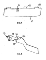
- Fig. 8 shows a to be connected to the terminal connection element 49 end portion of the connecting conductor piece 47 and 48 with terminal lugs 51 and 52.
- the conductor piece is made of a stamped sheet metal, in the edge of an incision to form cut edges 53 and 54 was made to make a fold at 55 to can, in the embodiment shown by 90 °.
- the closure plate 11 When mounting a power meter, the closure plate 11 is moved in the direction of arrow 13 to open the slots 14.
- the bridging parts 27 can now be moved into the bridging position with the aid of a special tool, which may be similar to the bottom part of a counter. After removing the tool, the counter can be placed, moved parallel to the support plate in the connection position and sealed in the connection position.
- the bridging parts 27 at both ends in conjunction with a contact piece 32.
- the conductor pieces 47 and 48 are electrically connected by the bridging members 27. Each phase is shorted.
- the nose 20 on the driver plate 10 moves out of the widening 22 of the opening 21 and is now displaceable in the opening 21 in the longitudinal direction.
- the contact elements pass through the slots 14 in the support plate, the slots 18 in the closure plate and the slots 19 in the driver plate therethrough. In this position, the contact elements of the electricity meter are still electrically separated from the contact pieces 32, wherein the projections 23 on the drive plate 10 for a secure insulation of the contact elements against the contact pieces 32 provide.
- the hooks 26 are pressed in the direction of the bottom of the box part 5 by its respective contact elements, so that the hooks 26 no longer engage behind the projections 24 on the driver plate 10.
- the counter can now be moved in the direction of the strip part 50 according to arrow 12.
- the contact elements whose width is equal to the length of the slots 19, take the plate 10, which in turn shifts the bridging parts 27, which engage with their lugs 29 in the slot openings 28 on the drive plate. In this process, the bridging is canceled while the respective contact elements of the electricity meter are connected to the no longer bridged contacts 32. In a bridging phase, the connection and the bridging exist simultaneously.
- the counter is displaced in the reverse direction, whereby a detachment of the contact elements of the electricity meter from the contact pieces 32 and restoration of the bridging through the parts 27 takes place.
- the return movement of the hook 26 slides over the slopes 25 of the projections 24. If the counter is removed from the support plate, so the hook 26 engages behind the projections 24.
- the driver plate 10 can not move according to arrow 12.
- the contact points can be relatively close to the plates, so that short contact elements on the electricity meter are sufficient to produce the connection connections.
- one of the two fields 70 on the drive plate 10 is visible at a remote counter through the windows 71 and 72 therethrough. Thus, the switch position is displayed.
- the driver plate 10 can not be moved from the position in which the bridging is canceled.
- the plug lock 75 also serves to lock and secure the patch counter, which is not displaced due to the locking of the drive plate on the support plate. If no drive plate is present, the lock can lock the counter by projecting out of the opening 73 and forms a stop for the meter housing. Deviation from the example shown, the plug lock could also be inserted laterally into the box part.
- Such a key lock could also be used on a counter space prepared for the use of the counter in question.
- FIGS. 9 and 10 Referring to a further embodiment for a connection device. Identical or equivalent parts are designated by the same reference number as in the preceding figures, the relevant reference number being accompanied by the letter a.
- FIG. 9 An in Fig. 9 separately shown, made of a spring strip of material contact element 32a has a U-shaped portion 38a with spring contact legs 40a and 41a and a U-shaped portion 39a with spring contact legs 42a and 43a on.
- the two U-shaped sections form in the in Fig. 9 shown an S-shape, wherein the spring contact leg 42a of the U-shaped portion 39a merges into the spring contact leg 41 a of the U-shaped portion 38a.
- the U-shaped section 39a is followed by another U-shaped section 63 with a spring contact leg 64 and a spring contact leg 46a.
- the spring contact leg 64 merges into the spring contact leg 43a of the U-shaped section 39a.
- Designated at 44a and 45a are guide tabs attached to the spring contact legs 42a and 43a.
- Fig. 10 shows a box part 5a of an adapter housing, in which the contact piece of Fig. 9 Connected between the spring contact legs 46a and 64 of the spring contact piece 32a 'is a conductor piece 47a (shown only partially) which leads to a terminal block 50a a conductor piece 48a (only partly shown) led to the strip 50a.
- the respective spring contact legs 40a and 41a serve for clamping a bridging part 27a. Between the respective spring contact legs 42a and 43a, a contact element protruding from the electricity meter comes to the connection.
- the length of the contact piece 32a in the direction of displacement of the electricity meter is compared to the length of the contact piece 32 shortened by about half. As a result of shorter current paths, the intrinsic resistance decreases accordingly.
- the spring contact leg 46a could also be non-springing and connected to a lead, e.g. be provided by welding or crimping.
Landscapes
- Engineering & Computer Science (AREA)
- Power Engineering (AREA)
- Physics & Mathematics (AREA)
- General Physics & Mathematics (AREA)
- Connector Housings Or Holding Contact Members (AREA)
- Led Device Packages (AREA)
- Details Of Measuring Devices (AREA)
- Led Devices (AREA)
- Details Of Connecting Devices For Male And Female Coupling (AREA)
- Electrophonic Musical Instruments (AREA)
- Measuring Pulse, Heart Rate, Blood Pressure Or Blood Flow (AREA)
- Arrangements For Transmission Of Measured Signals (AREA)
Description
- Die Erfindung betrifft eine Anschlussvorrichtung für einen Stromzähler, der ein Gehäuse aufweist, von dessen gegen eine Tragplatte anlegbarem Boden durch Öffnungen in der Tragplatte hindurchführbare Kontaktelemente entsprechend wenigstens einer Stromphase vorstehen, welche durch Verschiebung des auf der Tragplatte geführten Gehäuses mit stromzu- und -abführenden Anschlusselementen auf der dem Stromzähler abgewandten Seite der Tragplatte verbindbar sind, wobei die Anschlusselemente durch ein in Verschiebungsrichtung des Stromzählers verschiebbar geführtes Teil überbrückbar sind und das Überbrückungsteil beim Anschluss des Stromzählers durch den Stromzähler aus einer Überbrückungsposition in eine Offenstellung verschiebbar ist.
- Bei einer solchen, aus der
DE 103 13 999 A1 bekannten Anschlussvorrichtung greift das Kontaktelement in eine Ausnehmung in dem Überbrückungsteil ein, so dass das Überbrückungsteil bei Verschiebung des Zählers mitgenommen und in die Offenstellung überführt wird, während die Kontaktelemente mit Anschlussleitern verbunden werden. - Aus der
DE 100 52 998 A1 geht eine Anschlussvorrichtung hervor, bei der das Überbrückungsteil durch Federkontaktelemente mit abgebogenen Schenkeln gebildet ist, die in der Überbrückungsposition miteinander in Kontakt stehen und durch Verschiebung des Stromzählers unter Verbiegung der Schenkel durch die Kontaktelemente des Stromzählers dadurch in die Offenstellung gebracht werden, dass kein Kontakt mehr zwischen den Schenkeln besteht. - Der vorliegenden Erfindung liegt die Aufgabe zugrunde, eine Anschlussvorrichtung der eingangs erwähnten Art derart weiterzubilden, dass eine Verkürzung der Baulänge in Richtung der Verschiebung des Stromzählers möglich ist.
- Die diese Aufgabe lösende Vorrichtung nach der Erfindung ist dadurch gekennzeichnet, dass und das Überbrückurigsteil und das wenigstens eine Kontaktelement senkrecht zur Verschiebungsrichtung des Zählergehäuses zueinander versetzt angeordnet sind und das Überbrückungsteil durch den Stromzähler mittelbar über ein Zwischenstück verschiebbar ist.
- Im Unterschied zum Stand der Technik erfolgt die Verschiebung des Überbrückungsteils nicht unmittelbar durch das Kontaktelement, woraus sich Möglichkeiten insbesondere zur Anordnung von Anschlusselementen derart ergeben, dass sich eine insgesamt kürzere Baulänge erreichen lässt.
- Während es denkbar wäre, zur Verschiebung der Überbrückungsteile am Stromzählergehäuse entsprechende Mitnehmer, zusätzliche Öffnungen in der Tragplatte und ein Mitnehmerzwischenstück vorzusehen, erfolgt in der bevorzugten Ausführungsform der Erfindung die Bewegung des Überbrückungsteils durch das Kontaktelement, jedoch mittelbar über ein solches Mitnehmerzwischenstück.
- Bei dem Zwischenstück handelt es sich vorzugsweise um eine Öffnungen für die Kontaktelemente aufweisende Platte, mit Einrichtungen zur Mitnahme des Überbrückungsteils.
- Zwischen der Mitnehmerplatte und der Tragplatte kann eine weitere, quer zur Verschiebungsrichtung des Gehäuses bewegbare Verschlussplatte zum Verschließen von zu den Anschlusselementen durch die Öffnungen in den Platten führenden Durchgängen gebildet sein, welche zum Einsatz kommt, wenn am Zählerplatz kein Stromzähler angeschlossen ist. Vorzugsweise ist die Verschlussplatte in der Verschlussstellung plombierbar.
- In der bevorzugten Ausführungsform der Erfindung weisen die stromzu- und -abführenden Anschlusselemente sich senkrecht zur Verschiebungsrichtung des Zählergehäuses erstreckende Federkontaktschenkel auf. Zwischen diesen Federkontaktschenkeln lassen sich die Kontaktelemente bzw. das Überbrückungsteil seitlich einführen. Vorteilhaft erlauben solche Anschlusselemente kurze, von dem Stromzähler gehäuse nur über eine geringe Länge vorstehende Kontaktelemente.
- Vorzugsweise sind einteilige Kontaktstücke mit jeweils zwei senkrecht zur Verschiebungsrichtung des Zählergehäuses zueinander versetzten Paaren von Federkontaktschenkeln vorgesehen. An eines der Federkontaktschenkelpaare wird das jeweilige Kontaktelement angeschlossen. Das andere Federkontaktschenkelpaar dient der Kontaktierung des Überbrückungsteils.
- In weiterer Ausgestaltung der Erfindung kann an einem der Federschenkelpaare ein weiterer Federschenkel vorgesehen, welcher mit einem der beiden Federschenkel des betreffenden Federschenkelpaares einen Kontaktschlitz für einen Anschlussleiter bildet. Durch die genannten Maßnahmen lässt sich eine kurze Baulänge der Anschlussvorrichtung in Verschiebungsrichtung des Stromzählers erreichen.
- Zweckmäßig sind an den Federkontaktschenkeln die seitliche Einführung des Kontaktelements bzw. Überbrückungsteils erleichternde Leiteinrichtungen gebildet.
- Vorzugsweise sind an der Mitnehmerplatte in Verschiebungsrichtung ausgerichtet zu den Öffnungen für die Kontaktelemente Vorsprünge gebildet, welche, bevor es zur Kontaktierung kommt, die Anschlusselementen gegen die Kontaktelemente isolieren bzw. die Anschlusselemente verdecken, so dass bei verkantetem Aufsetzen des Stromzählers auf die Tragplatte keine spannungsführenden Teile freiliegen.
- Ferner kann eine beim Aufsetzen des Stromzählergehäuses auf die Tragplatte durch die Kontaktelemente lösbare Verhakung vorgesehen sein, welche verhindert, dass sich die Mitnehmerplatte von außen durch ein allgemein verfügbares Werkzeug, z.B. einen Schraubendreher, verschieben lässt, Bei schrägem Aufsetzen des Stromzählers auf die Tragplatte bleibt die Mitnehmerplatte vorteilhaft so lange in der Ausgangsposition, bis der Stromzähler ordnungsgemäß mit seiner gesamten Bodenfläche gegen die Zählertragplatte anliegt.
- In weiterer Ausgestaltung der Erfindung weist der Anschlussleiter einen Blechstreifen und einen an seinem dem Anschlusselement abgewandten Ende eine Kontaktfahne in Form einer bis an einen Randeinschnitt heranreichenden Abkantung auf.
- Bei dem obengenannten Kontaktstück kann es sich um einen S-förmig gebogenen Federmaterialstreifen handeln, wobei der Federmaterialstreifen vorzugsweise zur Bildung dreier Paare von Federkontaktschenkeln doppelt S-förmig gebogen sein kann. Ein solches Kontaktstück lässt sich in kurzer Baulänge herstellen, so dass sein Platzbedarf und Eigenwiderstand entsprechend gering sind. Die Verringerung der Baulänge ermöglicht im Gegenzug längere Verschiebewege des Überbrückungsteils. Dies ermöglicht es, ggf. auf die Verschlussplatte zu verzichten. Die Mitnehmerplatte könnte so weit verschoben werden, dass sie die Schlitze verschließt.
- Durch ein solches Kontaktelement ergibt sich ferner der Vorteil, dass die Leitungen an den oberen Kontaktfedern nach oben verlegt werden können, was erforderlich ist, wenn das Kontaktstück in einem für den betreffenden Stromzähler vorbereiteten Zählerplatz und nicht in einem Adapter eingesetzt wird.
- Die Erfindung wird nachfolgend anhand eines Ausführungsbeispiels und der beiliegenden, sich auf dieses Ausführungsbeispiel beziehenden Zeichnungen näher erläutert. Es zeigen:
- Fig. 1
- einen auf einen herkömmlichen Zählerplatz aufsetzbaren Stromzähleradapter mit einer Anschlussvorrichtung nach der Erfindung,
- Fig. 2
- den Adapter von
Fig. 1 in einer Explosionsdarstellung ohne stromleitende Teile, - Fig. 3
- eine in dem Adapter von
Fig. 1 verwendete Mitnehmerplatte, - Fig. 4
- eine Draufsicht auf den hinteren Gehäuseteil des Adapters von
Fig. 1 ohne stromführende Teile, - Fig. 5
- eine Teilansicht des hinteren Gehäuseteils mit stromführenden Teilen,
- Fig. 6
- ein in dem Adapter von
Fig. 1 verwendetes Kontaktstück mit zwei Paaren von Federkontaktschenkeln, - Fig. 7
- ein in dem Adapter von
Fig. 1 verwendetes Überbrückungsteil, - Fig. 8
- ein in dem Adapter von
Fig. 1 verwendetes Anschlussleiterstück, - Fig. 9
- ein weiteres Ausführungsbeispiel für ein Kontaktstück mit Federkontaktschenkelpaaren, und
- Fig. 10
- einen Kontaktstücke gemäß
Fig. 9 verwendenden Adapter. - Ein an einen herkömmlichen Zählerplatz montierbarer Adapter 1 für einen (nicht gezeigten) Stromzähler weist einen vorderen Gehäuseteil 2 mit einer Zählertragplatte 4 und einen hinteren Gehäuseteil 3 in Form eines halb offenen Kastens 5 auf.
- An die Zählertragplatte 4 und den halb offenen Kasten 5 schließt sich jeweils ein Abschnitt 6 bzw. 7 für die Bildung eines Anschlussleistenteils 50 des Adapters 1 an.
- Wie aus
Fig. 2 hervorgeht, ist der vordere Gehäuseteil 2 mit dem hinteren Gehäuseteil 3 über einrastende Stecknasen 8 verbindbar. - Vom Boden des unteren Gehäuseteils stehen stegförmig Isolierteile 9 vor, zwischen denen elektrischen Leiter angeordnet und gehalten sind.
- Zwischen den Isolierteilen 9 und der Zählertragplatte 4 sind eine Mitnehmerplatte 10 und eine Verschlussplatte 11 angeordnet.
- Von den zur Zählertragplatte 4 parallelen Platten 10 und 11 ist die Mitnehmerplatte 10 an dem hinteren Teil 3 des Zählergehäuses geführt und in Richtung eines Pfeils 12 hin und her verschiebbar. Die an der Rückseite der Zählertragplatte 4 geführte Verschlussplatte 11 lässt sich gemäß Pfeil 13 hin und her verschieben.
- Die Zählertragplatte 4 weist insgesamt sieben gleich lange Schlitze 14 auf, in welche streifenförmige, von der Unterseite eines Stromzählers vorstehende Kontaktelemente einführbar sind. Sechs Kontaktelemente sind für drei Stromphasen vorgesehen, ein Kontaktelement bildet den zum Betrieb des Stromzählers selbst erforderlichen Nullleiter.
- Die Verschlussplatte 11 weist zu den Schlitzen 14 deckungsgleiche Schlitze 18 bzw. Randausnehmungen auf. Von der Verschlussplatte steht eine Nase 15 in ein Fenster 16 in der Zählertragplatte vor. Über die Nase lässt sich die Verschlussplatte 11 gemäß Pfeil 13 verschieben. An der Nase 15 sind ferner Einrichtungen zur Plombierung der Verschlussplatte 11 in ihrer Verschlussstellung vorgesehen, in welcher sie sämtliche Öffnungen in der Tragplatte 4 von hinten verschließt. Eine Rastnase 17 rastet in der Verschlussstellung an der Rückseite der Zählertragplatte 4 ein.
- Die Mitnehmerplatte 10 weist den Schlitzen 14 in der Zählertragplatte 4 entsprechende Schlitze 19 auf, die jedoch kürzer als die Schlitze 14 sind und deren Länge in Verschiebungsrichtung gemäß Pfeil 12 gleich der Breite der streifenförmigen, von der Rückseite des (nicht gezeigten) Stromzählers vorstehenden Kontaktelementen ist. Eine Nase 20 auf der Mitnehmerplatte 10 ragt in eine Öffnung 21 in der Verschlussplatte 11 hinein, wobei die Öffnung 21 eine Aufweitung 22 aufweist. Die Verschlussplatte 11 lässt sich nur dann gemäß Pfeil 13 verschieben, wenn die Mitnehmerplatte 10 so verschoben ist, dass die Nase 20 in die Aufweitung 22 hinein ausweichen kann.
- In
Fig. 2 weist das Bezugszeichen 70 auf zwei verschieden farbige Felder auf der Mitnehmerplatte 10 hin, z.B. ein grünes und ein rotes Feld. Je nach Stellung der Mitnehmerplatte 10 ist eines der beiden Felder durch ein Fenster 71 in der Verschlussplatte 11 und ein Fenster 72 in der Zählertragplatte 4 hindurch sichtbar. - Wie
Fig. 2 ferner erkennen lässt, ist in der Zählertragplatte 4 eine Öffnung 73 für ein Steckschloss 75 vorgesehen, welches sich in einen Schacht 74 im Kastenteil 5 einschieben und befestigen lässt. Im eingeschobenen Zustand bildet das Steckschloss einen Anschlag für eine mit der Mitnehmerplatte 10 verbundene Zunge 76, welcher eine Verschiebung der Mitnehmerplatte 10 verhindert. - Wie
Fig. 3 erkennen lässt, weist die Mitnehmerplatte 10 auf ihrer den Isolierteilen 9 zugewandten Seite bei jedem der Schlitze 19 einen zu dem betreffenden Schlitz in Verschiebungsrichtung gemäß Pfeil 12 ausgerichteten Vorsprung 23 auf, dessen Stärke etwa gleich der Stärke der streifenförmigen Kontaktelemente ist, welche von dem Stromzähler durch die Schlitze 19 hindurch vorstehen. - Zwei weitere, in Richtung des Pfeils 12 zu den Schlitzen 19 ausgerichtete Vorsprünge 24 bilden ein Widerlager für einen flexiblen, mit dem unteren Gehäuseteil 4 verbundenen Haken 26. Wie
Fig. 3 erkennen lässt, weisen die Vorsprünge 24 jeweils eine Schräge 25 auf. Es könnten auch drei oder maximal sechs solcher Verhakungen vorgesehen sein. - In weitere Schlitzöffnungen 28 in der Mitnehmerplatte 10 greifen Nasen 29 ein, welche von drei Überbrückungsteilen 27 für drei Stromphasen vorstehen. Wie
Fig. 4 erkennen lässt, sind drei Führungen 30 für jeweils ein in Richtung des Pfeils 12 verschiebbares Überbrückungsteil 27 vorgesehen. Wenn kein Stromzähler angeschlossen ist, stehen beide Enden der Überbrückungsteile 27 in elektrischer Verbindung mit einem Kontaktstück 32, das inFig. 6 gesondert dargestellt ist. Wie durch Strichlinien angedeutet ist, könnten von der Mitnehmerplatte 10 auch Nasen 60 vorstehen, welche jeweils in eine Randausnehmung 61 im Überbrückungsteil 27 eingreifen oder gegen eine Randabwinklung 62 am Überbrückungsteil anschlagen. - An den Enden der Führungen 30 befindet sich im hinteren Gehäuseteil 3 jeweils eine Kammer 33 bzw. 34, welche in Verbindung mit einer weiteren Kammer 35 bzw. 36 steht. Die verbundenen Kammern 33 und 35 sowie die verbundenen Kammern 34 und 36 nehmen jeweils ein Kontaktstück 32 auf.
- Jedes Kontaktstück 32 besteht aus zwei bei 37 miteinander verbundene Abschnitten 38 und 39, welche jeweils ein Paar von Federkontaktschenkeln 40 und 41 bzw. 42 und 43 bilden. Die Abschnitte 38 und 39 sind in Richtung des Pfeils 13 zueinander versetzt. Gespreizte Führungsnasen 44 und 45 erleichtern die seitliche Einführung des Überbrückungsteils 27 bzw. der vom Stromzähler vorstehenden Kontaktelemente in den Zwischenraum zwischen den Federkontaktschenkeln.
- An den Federkontaktschenkel 42 der einteiligen Kontaktstücke schließt sich ein den Abschnitt 39 des Kontaktelements 32 im Querschnitt von der U-Form zu einer S-Form erweiternder Federkontaktschenkel 46 an, welcher mit dem Federkontaktschenkel 42 ein Schenkelpaar zur Kontaktierung eines Anschlussleiterstücks 47 bzw. 48 (
Fig. 5 ) bildet. Die gebogenen, zwischen isolierenden Stegen verlegten Anschlussleiterstücke 47,48 sind jeweils zu einem Klemmanschlusselement 49 an dem Anschlussleistenteil 50 des Adapters 1 geführt. Der Federkontaktschenkel 46 könnte auch nichtfedernd und zum Verbinden, z.B. durch Verschweißen oder Verkrimpen, mit einem Anschlussleiter vorgesehen sein. -
Fig. 8 zeigt einen an das Klemmanschlusselement 49 anzuschließenden Endteil des Anschlussleiterstücks 47 bzw. 48 mit Anschlussfahnen 51 und 52. Das Leiterstück ist aus einem Blechstanzteil hergestellt, in den am Rand ein Einschnitt unter Bildung von Schnittkanten 53 und 54 erfolgte, um bei 55 eine Abkantung vornehmen zu können, in dem gezeigten Ausführungsbeispiel um 90°. - Im folgenden wird die Funktionsweise der vorangehend beschriebenen Anschlussvorrichtung erläutert.
- Im Anlieferungszustand der vorangehend beschriebenen Anschlussvorrichtung, in welcher kein Stromzähler angeschlossen ist, sind die Überbrückungen geöffnet und die Schlitze 14 in der Zählertragplatte 4 durch die Verschlussplatte 11 verschlossen. Die Verschlussplatte 11 ist nicht plombiert.
- Bei der Montage eines Stromzählers wird die Verschlussplatte 11 in Richtung des Pfeils 13 verschoben, um die Schlitze 14 zu öffnen. Die Überbrückungsteile 27 lassen sich nun mit Hilfe eines speziellen Werkzeugs, das ähnlich dem Bodenteil eines Zählers ausgebildet sein kann, in die Überbrückungsposition verschieben. Nach Entfernen des Werkzeugs kann der Zähler aufgesetzt, parallel zur Tragplatte in die Anschlussposition verschoben und in der Anschlussposition plombiert werden.
- Bei einem Zählerwechsel wird die Plombe entfernt und der Zähler nach Verschiebung parallel zur Zählertragplatte in der Tragplatte abgenommen und dann ein neuer Zähler angeschlossen und plombiert.
- Um die Anlage außer Betrieb zu setzen, werden bei abgenommenen Zähler mit Hilfe des genannten Werkzeugs die Überbrückungsteile 27 in die Offenstellung verschoben, die Schlitze 14 mit Hilfe der Verschlussplatte 11 verschlossen und plombiert.
- Befindet sich kein Zähler auf der Tragplatte, so stehen, außer im Anlieferungszustand und bei Stilllegung, die Überbrückungsteile 27 an beiden Enden in Verbindung mit einem Kontaktstück 32. Die Leiterstücke 47 und 48 sind durch die Überbrückungsteile 27 elektrisch miteinander verbunden. Jede Phase ist kurzgeschlossen.
- Wird die Verschlussplatte gemäß Pfeil 13 verschoben, bewegt sich die Nase 20 auf der Mitnehmerplatte 10 aus der Aufweitung 22 der Öffnung 21 heraus und ist nun in Längsrichtung in der Öffnung 21 verschiebbar.
- Wird der Stromzähler senkrecht auf die Zählertragplatte 4 aufgesetzt, treten die Kontaktelemente durch die Schlitze 14 in der Tragplatte, die Schlitze 18 in der Verschlussplatte und die Schlitze 19 in der Mitnehmerplatte hindurch. In dieser Position sind die Kontaktelemente des Stromzählers noch elektrisch von den Kontaktstücken 32 getrennt, wobei die Vorsprünge 23 an der Mitnehmerplatte 10 für eine sichere Isolierung der Kontaktelemente gegen die Kontaktstücke 32 sorgen.
- Sitzt der Stromzähler korrekt auf der Tragplatte 4 auf, so sind durch dessen betreffende Kontaktelemente die Haken 26 in Richtung Boden des Kastenteils 5 gedrückt, so dass die Haken 26 die Vorsprünge 24 an der Mitnehmerplatte 10 nicht mehr hintergreifen. Der Zähler kann nun in Richtung zum Leistenteil 50 gemäß Pfeil 12 verschoben werden. Dabei nehmen die Kontaktelemente, deren Breite gleich der Länge der Schlitze 19 ist, die Platte 10 mit, welcher ihrerseits die Überbrückungsteile 27, welche mit ihren Nasen 29 in die Schlitzöffnungen 28 an der Mitnehmerplatte eingreifen, verschiebt. Bei diesem Vorgang wird die Überbrückung aufgehoben, während die betreffenden Kontaktelemente des Stromzählers an die nicht mehr überbrückten Kontaktstücke 32 angeschlossen werden. In einer Überbrückungsphase bestehen der Anschluss und die Überbrückung gleichzeitig.
- In der Anschlussstellung der Stromzähler sind alle Öffnungen der Zählertragplatte durch den Stromzähler selbst verschlossen. Einrichtungen zur Arretierung und Plombierung des Stromzählers sind in den Figuren nicht gezeigt.
- Bei der Demontage wird der Zähler in umgekehrter Richtung verschoben, wobei eine Loslösung der Kontaktelemente des Stromzählers von den Kontaktstücken 32 und Wiederherstellung der Überbrückungen durch die Teile 27 erfolgt. Bei der Rückverschiebung gleitet der Haken 26 über die Schrägen 25 der Vorsprünge 24. Wird der Zähler von der Tragplatte abgenommen, so hintergreift der Haken 26 wieder die Vorsprünge 24. Die Mitnehmerplatte 10 lässt sich nicht mehr gemäß Pfeil 12 verschieben.
- Vorteilhaft können durch die in Richtung senkrecht zu den Platten 10,11 vorstehenden Federkontaktschenkel die Kontaktpunkte relativ nahe an den Platten liegen, so dass kurze Kontaktelemente am Stromzähler ausreichen, um die Anschlussverbindungen herzustellen.
- Je nachdem, ob die stromzu- und -abführenden Leiter überbrückt sind oder nicht, ist bei abgesetztem Zähler durch die Fenster 71 und 72 hindurch eines der beiden Felder 70 auf der Mitnehmerplatte 10 sichtbar. Somit wird die Schaltstellung angezeigt.
- Solange das Steckschloss 75 in dem Schacht 74 sitzt, lässt sich die Mitnehmerplatte 10 aus der Position, in welcher die Überbrückung aufgehoben ist, nicht verschieben.
- Das Steckschloss 75 dient auch zur Arretierung und Sicherung des aufgesetzten Zählers, der wegen der Arretierung der Mitnehmerplatte auf der Tragplatte nicht verschiebbar ist. Wenn keine Mitnehmerplatte vorhanden ist, kann das Steckschloss den Zähler arretieren, indem es aus der Öffnung 73 vorsteht und einen Anschlag für das Zählergehäuse bildet. Abweichung von dem gezeigten Beispiel könnte das Steckschloss auch seitlich in den Kastenteil einführbar sein.
- Ein solches Steckschloss ließe sich auch an einem für den Einsatz der betreffenden Zähler vorbereiteten Zählerplatz verwenden.
- Es wird nun auf die
Fig. 9 und 10 Bezug genommen, die sich auf ein weiteres Ausführungsbeispiel für eine Anschlussvorrichtung beziehen. Gleiche oder gleichwirkende Teile sind mit derselben Bezugszahl wie in den vorangehenden Figuren bezeichnet, wobei der betreffenden Bezugszahl der Buchstabe a beigefügt ist. - Ein in
Fig. 9 gesondert dargestelltes, aus einem Federmaterialstreifen hergestellten Kontaktelement 32a weist einen U-förmigen Abschnitt 38a mit Federkontaktschenkeln 40a und 41 a sowie einen U-förmigen Abschnitt 39a mit Federkontaktschenkeln 42a und 43a auf. Die beiden U-förmigen Abschnitte bilden in der inFig. 9 gezeigten Ansicht eine S-Form, wobei der Federkontaktschenkel 42a des U-förmigen Abschnitts 39a in den Federkontaktschenkel 41 a des U-förmigen Abschnitts 38a übergeht. An den U-förmigen Abschnitt 39a schließt sich ein weiterer U-förmiger Abschnitt 63 mit einem Federkontaktschenkel 64 und einem Federkontaktschenkel 46a an. Der Federkontaktschenkel 64 geht in den Federkontaktschenkel 43a des U-förmigen Abschnitts 39a über. Mit 44a und 45a sind an den Federkontaktschenkeln 42a und 43a angebrachte Führungsnasen bezeichnet. - Weitere solche Führungsnasen sind an den Federkontaktschenkeln 40a und 46a vorgesehen.
-
Fig. 10 zeigt einen Kastenteil 5a eines Adaptergehäuses, in welche dem Kontaktstück vonFig. 9 entsprechende Kontaktstücke 32a' und 32a" eingesetzt sind. Zwischen den Federkontaktschenkeln 46a und 64 des Federkontaktstücks 32a' ist ein (nur teilweise dargestelltes) Leiterstück 47a angeschlossen, das zu einer Anschlussleiste 50a geführt ist. Die entsprechenden Federkontaktschenkel des Kontaktstücks 32a" stehen in Verbindung mit einem zu der Leiste 50a geführten (nur teilweise dargestellten) Leiterstück 48a. - Die jeweiligen Federkontaktschenkel 40a und 41 a dienen zur Anklemmung eines Überbrückungsteils 27a. Zwischen den jeweiligen Federkontaktschenkeln 42a und 43a kommt ein vom Stromzähler vorstehendes Kontaktelement zum Anschluss.
- Die Baulänge des Kontaktstücks 32a in Verschiebungsrichtung des Stromzählers ist gegenüber der Baulänge des Kontaktstücks 32 um etwa die Hälfte verkürzt. Infolge kürzerer Stromwege verringert sich der Eigenwiderstand entsprechend.
- Der Federkontaktschenkel 46a könnte auch nichtfedernd und zur Verbindung mit einem Anschlussleiter z.B. durch Verschweißen oder Verkrimpen vorgesehen sein.
Claims (17)
- Anschlussvorrichtung für einen Stromzähler, der ein Gehäuse aufweist, von dessen gegen eine Tragplatte (4) anlegbarem Boden durch Öffnungen (14) in der Tragplatte (4) hindurchführbare Kontaktelemente entsprechend wenigstens einer Stromphase vorstehen, welche durch Verschiebung des auf der Tragplatte (4) geführten Gehäuses mit stromzu- und -abführenden Anschlusselementen (32) auf der dem Stromzähler abgewandten Seite der Tragplatte (4) verbindbar sind, wobei die Anschlusselemente (32,47,48) durch ein in Verschiebungsrichtung des Stromzählers verschiebbar geführtes Teil (27) überbrückbar sind und das Überbrückungsteil (27) beim Anschluss des Stromzählers durch den Stromzähler aus einer Überbrückungsposition in eine Offenstellung verschiebbar ist,
dadurch gekennzeichnet,
dass das Überbrückungsteil (27) und das wenigstens eine Kontaktelement senkrecht zur Verschiebungsrichtung des Zählergehäuses zueinander versetzt angeordnet sind und das Überbrückungsteil (27.) durch den Stromzähler mittelbar über ein Zwischenstück (10) verschiebbar ist. - Anschlussvorrichtung nach Anspruch 1,
dadurch gekennzeichnet,
dass das Zwischenstück eine Öffnungen (19) für die Kontaktelemente aufweisende, zur Tragplatte (4) parallele Platte (10) mit Einrichtungen (28) zur Mitnahme des Überbrückungsteils (27) umfasst. - Anschlussvorrichtung nach Anspruch 2,
dadurch gekennzeichnet,
dass zwischen der Mitnehmerplatte (10) und der Tragplatte (4) eine weitere, quer zur Verschiebungsrichtung des Stromzählers bewegbare Verschlussplatte (11) zum Verschließen von zu den Anschlusselementen (32,47,48) führenden Durchgängen durch die Platten (4,10) vorgesehen ist. - Anschlussvorrichtung nach Anspruch 3,
dadurch gekennzeichnet,
dass die Verschlussplatte (11) in der Verschlussstellung plombierbar ist. - Anschlussvorrichtung nach einem der Ansprüche 1 bis 4,
dadurch gekennzeichnet,
dass die stromzu- und -abführenden Anschlusselemente (32,47,48) sich senkrecht zur Verschiebungsrichtung des Zählergehäuses erstreckende Federkontaktschenkel (40-43) aufweisen. - Anschlussvorrichtung nach Anspruch 5,
dadurch gekennzeichnet,
dass zwei senkrecht zur Verschiebungsrichtung des Zählergehäuses zueinander versetzte Paare von Federkontaktschenkeln (40,41;42,43) an einem einteiligen Kontaktstück (32) gebildet sind. - Anschlussvorrichtung nach Anspruch 6,
dadurch gekennzeichnet,
dass an einem der Paare von Federkontaktschenkeln (42,43) ein weiterer Federschenkel (46) vorgesehen ist, welcher mit einem (42) der beiden Federkontaktschenkel (42,43) des Paares einen Kontaktschlitz für einen Anschlussleiter (47,48) bildet. - Anschlussvorrichtung nach einem der Ansprüche 2 bis 7,
dadurch gekennzeichnet,
dass an der Mitnehmerplatte (10) in Verschiebungsrichtung ausgerichtet zu den Öffnungen (19) die Anschlusselemente (32) vor der Kontaktierung gegen die Kontaktelemente des Stromzählers isolierende Vorsprünge (23) gebildet sind. - Anschlussvorrichtung nach einem der Ansprüche 5 bis 8,
dadurch gekennzeichnet,
dass an den Federkontaktschenkeln (40-43) die seitliche Einführung des Kontaktelements bzw. des Überbrückungsteils (27) erleichternde Leiteinrichtungen (44,45) gebildet sind. - Anschlussvorrichtung nach einem der Ansprüche 1 bis 9,
dadurch gekennzeichnet,
dass eine unerwünschte Verschiebungen der Mitnehmerplatte (10) verhindernde, beim Aufsetzen des Stromzählergehäuses auf die Tragplatte (4) durch die Kontaktelemente lösbare Verhakung (26) vorgesehen ist. - Anschlussvorrichtung nach einem der Ansprüche 1 bis 10,
dadurch gekennzeichnet,
dass die Anschlusselemente Anschlussleiter (47,48) aufweisen, welche durch ein Blechstanzteil gebildet sind, wobei an einem Ende wenigstens eine Kontaktfahne (51,52) in Form einer bis zu einem Randeinschnitt (53,54) heranreichenden Abkantung (55) gebildet ist. - Anschlussvorrichtung nach einem der Ansprüche 6 bis 11,
dadurch gekennzeichnet,
dass es sich bei dem einteiligen Kontaktstück (32a) um einen S-förmig gebogenen Federmaterialstreifen handelt. - Anschlussvorrichtung nach Anspruch 12,
dadurch gekennzeichnet,
dass das einteilige Kontaktstück (32a) unter Bildung dreier Federkontaktschenkelpaare (38a,39a,63) doppelt S-förmig gebogen ist. - Anschlussvorrichtung nach einem der Ansprüche 1 bis 13,
dadurch gekennzeichnet,
dass das Zwischenstück (10) in der Offenstellung des Überbrückungsteils (27) arretierbar ist. - Anschlussvorrichtung nach Anspruch 14,
dadurch gekennzeichnet,
dass der Zähler in der Betriebsstellung über das Zwischenstück (10) arretierbar ist. - Anschlussvorrichtung nach Anspruch 14 oder 15,
dadurch gekennzeichnet,
dass zur Arretierung ein an der Anschlussvorrichtung festlegbares Steckschloss (75) vorgesehen ist. - Anschlussvorrichtung nach Anspruch 16,
dadurch gekennzeichnet,
dass das festgelegte Steckschloss (75) einen Anschlag für das Zwischenstück (10) bzw. den Zähler bildet.
Applications Claiming Priority (4)
| Application Number | Priority Date | Filing Date | Title |
|---|---|---|---|
| DE102004019129 | 2004-04-16 | ||
| DE102004019129 | 2004-04-16 | ||
| DE102004025605A DE102004025605A1 (de) | 2004-04-16 | 2004-05-19 | Anschlussvorrichtung für einen Stromzähler |
| DE102004025605 | 2004-05-19 |
Publications (2)
| Publication Number | Publication Date |
|---|---|
| EP1586908A1 EP1586908A1 (de) | 2005-10-19 |
| EP1586908B1 true EP1586908B1 (de) | 2010-05-12 |
Family
ID=34934753
Family Applications (1)
| Application Number | Title | Priority Date | Filing Date |
|---|---|---|---|
| EP05007360A Expired - Lifetime EP1586908B1 (de) | 2004-04-16 | 2005-04-05 | Anschlussvorrichtung für einen Stromzähler |
Country Status (3)
| Country | Link |
|---|---|
| EP (1) | EP1586908B1 (de) |
| AT (1) | ATE467841T1 (de) |
| DE (2) | DE102004025605A1 (de) |
Families Citing this family (12)
| Publication number | Priority date | Publication date | Assignee | Title |
|---|---|---|---|---|
| DE102004022127A1 (de) * | 2004-05-05 | 2005-12-01 | Abb Patent Gmbh | Stromzählereinrichtung |
| DE102004055820B4 (de) * | 2004-06-08 | 2010-07-08 | Hager Electro Gmbh | Zählerplatz |
| DE102006038739A1 (de) * | 2006-08-17 | 2008-03-20 | Abb Patent Gmbh | Plattform zum Aufstecken eines Stromzählers |
| DE102006040094A1 (de) * | 2006-08-28 | 2008-03-06 | Hager Electro Gmbh & Co. Kg | Zähleranschlussplatz |
| EP1901078A3 (de) * | 2006-09-14 | 2012-04-04 | Hager Electro GmbH & Co. KG | Anschlussvorrichtung für einen Strohmzähler |
| ATE510329T1 (de) | 2006-09-14 | 2011-06-15 | Hager Electro Gmbh & Co Kg | Verbindungsstück zur herstellung eines elektrischen kontakts |
| DE102008062409A1 (de) * | 2008-12-17 | 2010-06-24 | Hager Electro Gmbh & Co. Kg | Stromzähleranschlussinstallation |
| DE102009049853A1 (de) * | 2009-06-25 | 2010-12-30 | Hager Electro Gmbh & Co. Kg | Element zur Überbrückung zueinander im Abstand angeordneter elektrischer Leiter |
| DE102009031989A1 (de) * | 2009-07-06 | 2011-01-13 | Hager Electro Gmbh & Co. Kg | Abdeckung für den Anschlussplatz eines Stromzählers |
| DE102009053940A1 (de) * | 2009-11-19 | 2011-05-26 | Hager Electro Gmbh & Co. Kg | Anschlussvorrichtung für einen elektronischen Stromzähler |
| DE202010006202U1 (de) * | 2010-04-08 | 2010-08-05 | Braun, Werner | Adapter für einen elektronischen Haushaltszähler |
| CH718347B1 (de) | 2022-05-06 | 2022-12-15 | Eweco Gmbh | Elektrische Federkontaktklemme für eine Zählersteckklemme. |
Family Cites Families (7)
| Publication number | Priority date | Publication date | Assignee | Title |
|---|---|---|---|---|
| DE2711808A1 (de) * | 1977-03-18 | 1978-09-21 | Bbc Brown Boveri & Cie | Zaehlerplatz mit einer vorrichtung zur stromzaehlerueberbrueckung |
| FR2738955B1 (fr) * | 1995-09-15 | 1997-10-24 | Schneider Electric Sa | Prise electrique a detrompage |
| US5870911A (en) * | 1996-01-22 | 1999-02-16 | Dewalch; Norman Binz | Electric meter box lock |
| DE10054771B4 (de) * | 2000-10-23 | 2004-11-25 | Geyer Ag | Befestigungs- und Kontaktiereinrichtung |
| DE10052998B4 (de) * | 2000-10-24 | 2004-10-07 | Hager Electro Gmbh | Aufnahmeplattform für eine Stromzählereinheit |
| DE10261206B4 (de) * | 2002-12-20 | 2007-04-26 | Hager Electro Gmbh | Adapter zur Ankopplung eines Stromzählers an eine ein Zählerkreuz aufweisende Trägerplattform |
| DE10313999A1 (de) * | 2003-03-27 | 2004-10-07 | Hager Electro Gmbh | Anschlussvorrichtung für einen Stromzähler |
-
2004
- 2004-05-19 DE DE102004025605A patent/DE102004025605A1/de not_active Withdrawn
-
2005
- 2005-04-05 EP EP05007360A patent/EP1586908B1/de not_active Expired - Lifetime
- 2005-04-05 DE DE502005009551T patent/DE502005009551D1/de not_active Expired - Lifetime
- 2005-04-05 AT AT05007360T patent/ATE467841T1/de active
Also Published As
| Publication number | Publication date |
|---|---|
| EP1586908A1 (de) | 2005-10-19 |
| ATE467841T1 (de) | 2010-05-15 |
| DE502005009551D1 (de) | 2010-06-24 |
| DE102004025605A1 (de) | 2005-11-03 |
Similar Documents
| Publication | Publication Date | Title |
|---|---|---|
| DE4241163C2 (de) | Mechanismus zum elektrischen Verbinden und Lösen von Dunkelstromsicherungen mit jeweiligen Kontaktelementen | |
| EP0899818B1 (de) | Elektrische Anschlussklemme, insbesondere für den Einsatz auf Leiterplatten | |
| EP1794463B1 (de) | Vorrichtung zum verriegeln von elektrogeräten, insbesondere von elektrowerkzeugen, mit batteriepacks zur stromversorgung | |
| EP1253670B1 (de) | Federklemme und Federklemmenreihung | |
| EP3284139B1 (de) | Federklemme | |
| EP0730785A1 (de) | Anschlussklemme für elektrische installationen | |
| DE2425462C2 (de) | Elektrischer Buchsenkontakt | |
| DE29722506U1 (de) | Sicherheitssteckdose | |
| DE1230879B (de) | Tastenstreifen mit auswechselbaren Kontaktkombinationen | |
| EP1586908A1 (de) | Anschlussvorrichtung für einen Stromzähler | |
| EP0857361B1 (de) | Klemmkontakteinrichtung | |
| DE2028499B2 (de) | Elektrische Schaltvorrichtung | |
| DE19735168A1 (de) | Elektrischer Steckverbinder | |
| DE19702373A1 (de) | Elektrischer Steckverbinder mit einer Kurzschlußfeder und Kurzschlußfeder | |
| DE3523446C2 (de) | ||
| EP0745260A1 (de) | Trennkontaktblock mit relativ zueinander bewegbar angeordneten brückenartigen kontaktstücken | |
| EP1462808B1 (de) | Anschlussvorrichtung für einen Stromzähler | |
| DE19532623B4 (de) | Elektrischer Stecker mit einem Betätigungsschieber | |
| DE3219294A1 (de) | Schaltvorrichtung fuer elektrische schalter, vorzugsweise fuer installationszwecke | |
| DE19964616B4 (de) | Klemme zum elektrischen Verbinden wenigstens eines elektrischen Kontaktelements mit einem Leiterdraht und Verfahren zum Montieren einer Klemme | |
| DE19709198B4 (de) | Steckeranordnung mit einem Betätigungsschieber | |
| EP1544627B1 (de) | Anschlussvorrichtung für einen Stromzähler | |
| EP1544629B1 (de) | Anschlussvorrichtung für einen Stromzähler | |
| EP1612566A1 (de) | Sperre zur Blockierung eines Funktionselements | |
| EP1593975A1 (de) | Stromzählereinrichtung |
Legal Events
| Date | Code | Title | Description |
|---|---|---|---|
| PUAI | Public reference made under article 153(3) epc to a published international application that has entered the european phase |
Free format text: ORIGINAL CODE: 0009012 |
|
| AK | Designated contracting states |
Kind code of ref document: A1 Designated state(s): AT BE BG CH CY CZ DE DK EE ES FI FR GB GR HU IE IS IT LI LT LU MC NL PL PT RO SE SI SK TR |
|
| AX | Request for extension of the european patent |
Extension state: AL BA HR LV MK YU |
|
| 17P | Request for examination filed |
Effective date: 20060321 |
|
| AKX | Designation fees paid |
Designated state(s): AT BE BG CH CY CZ DE DK EE ES FI FR GB GR HU IE IS IT LI LT LU MC NL PL PT RO SE SI SK TR |
|
| 17Q | First examination report despatched |
Effective date: 20071115 |
|
| GRAP | Despatch of communication of intention to grant a patent |
Free format text: ORIGINAL CODE: EPIDOSNIGR1 |
|
| GRAS | Grant fee paid |
Free format text: ORIGINAL CODE: EPIDOSNIGR3 |
|
| GRAA | (expected) grant |
Free format text: ORIGINAL CODE: 0009210 |
|
| RAP1 | Party data changed (applicant data changed or rights of an application transferred) |
Owner name: HAGER ELECTRO GMBH & CO. KG |
|
| AK | Designated contracting states |
Kind code of ref document: B1 Designated state(s): AT BE BG CH CY CZ DE DK EE ES FI FR GB GR HU IE IS IT LI LT LU MC NL PL PT RO SE SI SK TR |
|
| REG | Reference to a national code |
Ref country code: GB Ref legal event code: FG4D Free format text: NOT ENGLISH |
|
| REG | Reference to a national code |
Ref country code: CH Ref legal event code: EP |
|
| REG | Reference to a national code |
Ref country code: CH Ref legal event code: NV Representative=s name: ALDO ROEMPLER PATENTANWALT |
|
| REG | Reference to a national code |
Ref country code: IE Ref legal event code: FG4D Free format text: LANGUAGE OF EP DOCUMENT: GERMAN |
|
| REF | Corresponds to: |
Ref document number: 502005009551 Country of ref document: DE Date of ref document: 20100624 Kind code of ref document: P |
|
| REG | Reference to a national code |
Ref country code: NL Ref legal event code: VDEP Effective date: 20100512 |
|
| LTIE | Lt: invalidation of european patent or patent extension |
Effective date: 20100512 |
|
| PG25 | Lapsed in a contracting state [announced via postgrant information from national office to epo] |
Ref country code: NL Free format text: LAPSE BECAUSE OF FAILURE TO SUBMIT A TRANSLATION OF THE DESCRIPTION OR TO PAY THE FEE WITHIN THE PRESCRIBED TIME-LIMIT Effective date: 20100512 Ref country code: LT Free format text: LAPSE BECAUSE OF FAILURE TO SUBMIT A TRANSLATION OF THE DESCRIPTION OR TO PAY THE FEE WITHIN THE PRESCRIBED TIME-LIMIT Effective date: 20100512 Ref country code: ES Free format text: LAPSE BECAUSE OF FAILURE TO SUBMIT A TRANSLATION OF THE DESCRIPTION OR TO PAY THE FEE WITHIN THE PRESCRIBED TIME-LIMIT Effective date: 20100823 Ref country code: SE Free format text: LAPSE BECAUSE OF FAILURE TO SUBMIT A TRANSLATION OF THE DESCRIPTION OR TO PAY THE FEE WITHIN THE PRESCRIBED TIME-LIMIT Effective date: 20100512 |
|
| PG25 | Lapsed in a contracting state [announced via postgrant information from national office to epo] |
Ref country code: SI Free format text: LAPSE BECAUSE OF FAILURE TO SUBMIT A TRANSLATION OF THE DESCRIPTION OR TO PAY THE FEE WITHIN THE PRESCRIBED TIME-LIMIT Effective date: 20100512 Ref country code: IS Free format text: LAPSE BECAUSE OF FAILURE TO SUBMIT A TRANSLATION OF THE DESCRIPTION OR TO PAY THE FEE WITHIN THE PRESCRIBED TIME-LIMIT Effective date: 20100912 Ref country code: FI Free format text: LAPSE BECAUSE OF FAILURE TO SUBMIT A TRANSLATION OF THE DESCRIPTION OR TO PAY THE FEE WITHIN THE PRESCRIBED TIME-LIMIT Effective date: 20100512 |
|
| REG | Reference to a national code |
Ref country code: IE Ref legal event code: FD4D |
|
| PG25 | Lapsed in a contracting state [announced via postgrant information from national office to epo] |
Ref country code: CY Free format text: LAPSE BECAUSE OF FAILURE TO SUBMIT A TRANSLATION OF THE DESCRIPTION OR TO PAY THE FEE WITHIN THE PRESCRIBED TIME-LIMIT Effective date: 20100512 Ref country code: PL Free format text: LAPSE BECAUSE OF FAILURE TO SUBMIT A TRANSLATION OF THE DESCRIPTION OR TO PAY THE FEE WITHIN THE PRESCRIBED TIME-LIMIT Effective date: 20100512 Ref country code: GR Free format text: LAPSE BECAUSE OF FAILURE TO SUBMIT A TRANSLATION OF THE DESCRIPTION OR TO PAY THE FEE WITHIN THE PRESCRIBED TIME-LIMIT Effective date: 20100813 |
|
| PG25 | Lapsed in a contracting state [announced via postgrant information from national office to epo] |
Ref country code: EE Free format text: LAPSE BECAUSE OF FAILURE TO SUBMIT A TRANSLATION OF THE DESCRIPTION OR TO PAY THE FEE WITHIN THE PRESCRIBED TIME-LIMIT Effective date: 20100512 Ref country code: DK Free format text: LAPSE BECAUSE OF FAILURE TO SUBMIT A TRANSLATION OF THE DESCRIPTION OR TO PAY THE FEE WITHIN THE PRESCRIBED TIME-LIMIT Effective date: 20100512 Ref country code: PT Free format text: LAPSE BECAUSE OF FAILURE TO SUBMIT A TRANSLATION OF THE DESCRIPTION OR TO PAY THE FEE WITHIN THE PRESCRIBED TIME-LIMIT Effective date: 20100913 Ref country code: IE Free format text: LAPSE BECAUSE OF FAILURE TO SUBMIT A TRANSLATION OF THE DESCRIPTION OR TO PAY THE FEE WITHIN THE PRESCRIBED TIME-LIMIT Effective date: 20100512 |
|
| PG25 | Lapsed in a contracting state [announced via postgrant information from national office to epo] |
Ref country code: RO Free format text: LAPSE BECAUSE OF FAILURE TO SUBMIT A TRANSLATION OF THE DESCRIPTION OR TO PAY THE FEE WITHIN THE PRESCRIBED TIME-LIMIT Effective date: 20100512 Ref country code: CZ Free format text: LAPSE BECAUSE OF FAILURE TO SUBMIT A TRANSLATION OF THE DESCRIPTION OR TO PAY THE FEE WITHIN THE PRESCRIBED TIME-LIMIT Effective date: 20100512 Ref country code: SK Free format text: LAPSE BECAUSE OF FAILURE TO SUBMIT A TRANSLATION OF THE DESCRIPTION OR TO PAY THE FEE WITHIN THE PRESCRIBED TIME-LIMIT Effective date: 20100512 |
|
| PLBE | No opposition filed within time limit |
Free format text: ORIGINAL CODE: 0009261 |
|
| STAA | Information on the status of an ep patent application or granted ep patent |
Free format text: STATUS: NO OPPOSITION FILED WITHIN TIME LIMIT |
|
| PG25 | Lapsed in a contracting state [announced via postgrant information from national office to epo] |
Ref country code: IT Free format text: LAPSE BECAUSE OF FAILURE TO SUBMIT A TRANSLATION OF THE DESCRIPTION OR TO PAY THE FEE WITHIN THE PRESCRIBED TIME-LIMIT Effective date: 20100512 |
|
| 26N | No opposition filed |
Effective date: 20110215 |
|
| REG | Reference to a national code |
Ref country code: DE Ref legal event code: R097 Ref document number: 502005009551 Country of ref document: DE Effective date: 20110214 |
|
| PG25 | Lapsed in a contracting state [announced via postgrant information from national office to epo] |
Ref country code: MC Free format text: LAPSE BECAUSE OF NON-PAYMENT OF DUE FEES Effective date: 20110430 |
|
| GBPC | Gb: european patent ceased through non-payment of renewal fee |
Effective date: 20110405 |
|
| PG25 | Lapsed in a contracting state [announced via postgrant information from national office to epo] |
Ref country code: GB Free format text: LAPSE BECAUSE OF NON-PAYMENT OF DUE FEES Effective date: 20110405 |
|
| PGFP | Annual fee paid to national office [announced via postgrant information from national office to epo] |
Ref country code: BE Payment date: 20120424 Year of fee payment: 8 Ref country code: CH Payment date: 20120412 Year of fee payment: 8 |
|
| PGFP | Annual fee paid to national office [announced via postgrant information from national office to epo] |
Ref country code: AT Payment date: 20120420 Year of fee payment: 8 |
|
| PG25 | Lapsed in a contracting state [announced via postgrant information from national office to epo] |
Ref country code: LU Free format text: LAPSE BECAUSE OF NON-PAYMENT OF DUE FEES Effective date: 20110405 |
|
| PG25 | Lapsed in a contracting state [announced via postgrant information from national office to epo] |
Ref country code: TR Free format text: LAPSE BECAUSE OF FAILURE TO SUBMIT A TRANSLATION OF THE DESCRIPTION OR TO PAY THE FEE WITHIN THE PRESCRIBED TIME-LIMIT Effective date: 20100512 Ref country code: BG Free format text: LAPSE BECAUSE OF FAILURE TO SUBMIT A TRANSLATION OF THE DESCRIPTION OR TO PAY THE FEE WITHIN THE PRESCRIBED TIME-LIMIT Effective date: 20100812 |
|
| BERE | Be: lapsed |
Owner name: HAGER ELECTRO G.M.B.H. & CO. KG Effective date: 20130430 |
|
| PG25 | Lapsed in a contracting state [announced via postgrant information from national office to epo] |
Ref country code: HU Free format text: LAPSE BECAUSE OF FAILURE TO SUBMIT A TRANSLATION OF THE DESCRIPTION OR TO PAY THE FEE WITHIN THE PRESCRIBED TIME-LIMIT Effective date: 20100512 |
|
| REG | Reference to a national code |
Ref country code: CH Ref legal event code: PL |
|
| REG | Reference to a national code |
Ref country code: AT Ref legal event code: MM01 Ref document number: 467841 Country of ref document: AT Kind code of ref document: T Effective date: 20130430 |
|
| PG25 | Lapsed in a contracting state [announced via postgrant information from national office to epo] |
Ref country code: AT Free format text: LAPSE BECAUSE OF NON-PAYMENT OF DUE FEES Effective date: 20130430 Ref country code: LI Free format text: LAPSE BECAUSE OF NON-PAYMENT OF DUE FEES Effective date: 20130430 Ref country code: BE Free format text: LAPSE BECAUSE OF NON-PAYMENT OF DUE FEES Effective date: 20130430 Ref country code: CH Free format text: LAPSE BECAUSE OF NON-PAYMENT OF DUE FEES Effective date: 20130430 |
|
| REG | Reference to a national code |
Ref country code: DE Ref legal event code: R082 Ref document number: 502005009551 Country of ref document: DE Representative=s name: PATENTANWAELTE BERNHARDT/WOLFF PARTNERSCHAFT, DE Ref country code: DE Ref legal event code: R082 Ref document number: 502005009551 Country of ref document: DE Representative=s name: CABINET NUSS, FR |
|
| REG | Reference to a national code |
Ref country code: DE Ref legal event code: R082 Ref document number: 502005009551 Country of ref document: DE Representative=s name: CABINET NUSS, FR |
|
| REG | Reference to a national code |
Ref country code: FR Ref legal event code: PLFP Year of fee payment: 12 |
|
| REG | Reference to a national code |
Ref country code: FR Ref legal event code: PLFP Year of fee payment: 13 |
|
| REG | Reference to a national code |
Ref country code: FR Ref legal event code: PLFP Year of fee payment: 14 |
|
| PGFP | Annual fee paid to national office [announced via postgrant information from national office to epo] |
Ref country code: FR Payment date: 20180425 Year of fee payment: 14 |
|
| PG25 | Lapsed in a contracting state [announced via postgrant information from national office to epo] |
Ref country code: FR Free format text: LAPSE BECAUSE OF NON-PAYMENT OF DUE FEES Effective date: 20190430 |
|
| P01 | Opt-out of the competence of the unified patent court (upc) registered |
Effective date: 20230606 |
|
| PGFP | Annual fee paid to national office [announced via postgrant information from national office to epo] |
Ref country code: DE Payment date: 20240429 Year of fee payment: 20 |
|
| REG | Reference to a national code |
Ref country code: DE Ref legal event code: R071 Ref document number: 502005009551 Country of ref document: DE |