EP1586932B1 - Système actif de vision nocturne pour véhicule automobile - Google Patents
Système actif de vision nocturne pour véhicule automobile Download PDFInfo
- Publication number
- EP1586932B1 EP1586932B1 EP05106599A EP05106599A EP1586932B1 EP 1586932 B1 EP1586932 B1 EP 1586932B1 EP 05106599 A EP05106599 A EP 05106599A EP 05106599 A EP05106599 A EP 05106599A EP 1586932 B1 EP1586932 B1 EP 1586932B1
- Authority
- EP
- European Patent Office
- Prior art keywords
- image
- camera
- range
- vision system
- exposure
- Prior art date
- Legal status (The legal status is an assumption and is not a legal conclusion. Google has not performed a legal analysis and makes no representation as to the accuracy of the status listed.)
- Revoked
Links
Images


Classifications
-
- G—PHYSICS
- G02—OPTICS
- G02B—OPTICAL ELEMENTS, SYSTEMS OR APPARATUS
- G02B27/00—Optical systems or apparatus not provided for by any of the groups G02B1/00 - G02B26/00, G02B30/00
- G02B27/01—Head-up displays
-
- H—ELECTRICITY
- H04—ELECTRIC COMMUNICATION TECHNIQUE
- H04N—PICTORIAL COMMUNICATION, e.g. TELEVISION
- H04N23/00—Cameras or camera modules comprising electronic image sensors; Control thereof
- H04N23/10—Cameras or camera modules comprising electronic image sensors; Control thereof for generating image signals from different wavelengths
- H04N23/11—Cameras or camera modules comprising electronic image sensors; Control thereof for generating image signals from different wavelengths for generating image signals from visible and infrared light wavelengths
-
- G—PHYSICS
- G02—OPTICS
- G02B—OPTICAL ELEMENTS, SYSTEMS OR APPARATUS
- G02B23/00—Telescopes, e.g. binoculars; Periscopes; Instruments for viewing the inside of hollow bodies; Viewfinders; Optical aiming or sighting devices
- G02B23/12—Telescopes, e.g. binoculars; Periscopes; Instruments for viewing the inside of hollow bodies; Viewfinders; Optical aiming or sighting devices with means for image conversion or intensification
-
- H—ELECTRICITY
- H04—ELECTRIC COMMUNICATION TECHNIQUE
- H04N—PICTORIAL COMMUNICATION, e.g. TELEVISION
- H04N23/00—Cameras or camera modules comprising electronic image sensors; Control thereof
- H04N23/20—Cameras or camera modules comprising electronic image sensors; Control thereof for generating image signals from infrared radiation only
- H04N23/21—Cameras or camera modules comprising electronic image sensors; Control thereof for generating image signals from infrared radiation only from near infrared [NIR] radiation
-
- G—PHYSICS
- G02—OPTICS
- G02B—OPTICAL ELEMENTS, SYSTEMS OR APPARATUS
- G02B27/00—Optical systems or apparatus not provided for by any of the groups G02B1/00 - G02B26/00, G02B30/00
- G02B27/01—Head-up displays
- G02B27/0101—Head-up displays characterised by optical features
- G02B2027/0138—Head-up displays characterised by optical features comprising image capture systems, e.g. camera
Definitions
- the invention relates to an infrared night vision system for motor vehicles.
- Such a system is for example from the DE 695 06 174 T2 known.
- an image taken with an infrared camera is projected into the windshield via a head-up display.
- the video processor of the camera can be placed in a so-called object second mode by setting a threshold to suppress weak (cold) signals to represent only the warmer objects ,
- the system according to DE 695 06 174 T2 however, has two major disadvantages. For one thing, it is not always the warmer objects that can be dangerous in a collision. On the other hand, in the object evidence mode, the information about the environment of the warmer objects is lost.
- FR 2 661 268 A1 discloses a night vision system for motor vehicles having an infrared radiation transmitter for generating active IR illumination, wherein an image is captured in the infrared and an image in the visible region.
- two cameras are provided for this purpose, the one camera being equipped with an optical bandpass filter.
- alternately two different optical filters are connected in front of a camera.
- the object of the invention is to provide an infrared night vision system which makes attention in an improved way to important objects in the infrared image.
- the basic idea of the invention is to record at least two images which are exposed to light / radiation from at least partially different wavelength ranges, wherein at least one of the wavelength ranges lies at least partially in the infrared range. Subsequently, the two images are linked together in an image processing unit, preferably compared. The display and warning unit is activated depending on the result of the linkage.
- the two images contain at least partially different image information, since they were recorded with light from different wavelength ranges.
- a night-vision system with active IR illumination is used, so that one does not rely on the intrinsic heat of the same for the visualization of objects.
- a first image is taken with at least one camera without exposure with active IR illumination, ie only with normal headlight illumination.
- a second image is taken under exposure to active IR illumination.
- An IR image taken with a night-vision system contains, in addition to the image information that can only be perceived via the night vision system, redundant image information that is also perceived by the naked eye during normal headlight illumination.
- the overloading of the IR image with this redundant information makes it difficult for the driver to quickly perceive the really important image information that is only present in the IR image.
- relevant objects in front of the vehicle which the driver can only perceive with a night vision system, can be effectively filtered out by linking the image information of the two images (with and without IR exposure).
- the display or warning unit is then activated depending on the result of the linkage.
- the attention of the driver is directed particularly to relevant objects that are perceptible only by night vision system.
- the combination of the two images in the image processing unit preferably consists in a comparison of the two images, wherein by comparing the two images image information is extracted, which are present only in the image taken with IR exposure.
- the comparison of the two images in the image processing unit preferably consists in that the two images for generating a difference image from each other are subtracted by subtracting the brightness values of corresponding pixels or the mean brightness values of corresponding pixel clusters (hyperpixels) from each other.
- a relevant object is detected by comparing the two images, which was only detectable by IR exposure, only an acoustic and / or visual warning signal is generated.
- a warning signal is sent to an automatic driver assistance system, e.g. an automatic distance control system (Adaptive Cruise Control) given.
- an automatic driver assistance system e.g. an automatic distance control system (Adaptive Cruise Control) given.
- the difference image is marked, wherein the difference image contains the image information that is present only in the image taken with IR exposure.
- the marked differential image is inserted as contour-accurate as possible into an overall image to produce an image to be displayed on a display as a display unit.
- an image of the scene in front of the vehicle is obtained, wherein the image sections, which are only noticeable with IR exposure, are highlighted by the marking, while the image areas, which are also perceptible to the driver with normal headlight illumination, are less emphasized because they only serve to orient and embed the marked image in an overall scene.
- the marking may consist, for example, in a coloring or border of the difference image.
- the overall image into which the difference image is inserted may be the image taken with IR exposure or the image taken without IR exposure, ie only with headlight illumination.
- the two images are separately subjected to image preprocessing prior to linking, where the images can each be adjusted (normalized) to predetermined initial values for the comparison, eg with regard to brightness, contrast etc.
- FIG. 1 shows the block diagram of a first embodiment of the night vision system according to the invention with only one (“digital") camera, which is sensitive to both visible light and light from the near IR range.
- a camera with a photosensitive semiconductor sensor in the form of a two-dimensional array consisting of a plurality of sensor pixels is used.
- the use of such a camera allows the digital processing of the image information of the individual pixels in a simple manner.
- FIG. 6 shows the typical spectral sensitivity of a semiconductor sensor used in a camera that is sensitive to both visible light and near IR light. In this case, the near IR region adjoining the visible region is hatched.
- a camera with such a sensitivity is "blind" to infrared radiation, which is based on the intrinsic heat of objects at ambient temperature (-10 ° C to + 30 ° C), as these radiate predominantly in the mid to far IR range (> 3 ⁇ m). Without active IR illumination in the near IR range, such a camera would only be exposed to visible light.
- an IR transmitter preferably an IR diode, is provided, which emits light in the near IR range with an emission maximum between 900 nm and 1 ⁇ m.
- the IR transmitter is clocked, eg with a clock frequency of 25Hz, operated, the two images are already recorded almost simultaneously at a clock frequency of 25Hz.
- the clocked control of the IR transmitter via a control unit.
- the IR transmitter is switched on, exposure is then effected by means of light from the near IR range and by means of visible light Light that is mainly generated by the porpoises.
- the IR transmitter is switched off, exposure is then only possible with visible light due to the headlight illumination.
- the images thus taken - or the digitized image information of the individual pixels of the semiconductor sensor - are temporarily stored in an image memory before they are fed to an image processing unit for image comparison. Depending on the result of this image comparison, the display / warning unit is now activated.
- the image processing unit may be a computer-implemented program or else a hardware circuit.
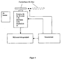
- FIG. 4 shows the block diagram of a second, non-inventive embodiment of the night vision system with also only one camera (see first embodiment according to Fig. 1 ) which is sensitive to both visible light and near IR light.
- the IR transmitter is not operated clocked here, but continuously.
- an optical filter is provided which transmits only visible light, so that the exposure of the camera with the aid of the optical filter is optionally possible with infrared light or prevented.
- the IR filter is switched on and off by bringing it, for example, mechanically in front of the camera lens for exposure without IR exposure and removing it again for exposure with IR exposure.
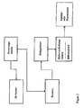
- FIG. 3 shows the block diagram of a third, non-inventive embodiment of the night vision system with two cameras, one of which is sensitive only to visible light, while the other is sensitive to visible light and light from the near IR range.
- an IR transmitter is also provided. In the case of continuous operation of the IR transmitter, with this embodiment, one image at a time is exposed only to light from the visible region and one image exposed to light from the visible region and the near IR region.
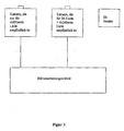
- FIG. 2 shows the block diagram of a fourth, non-inventive embodiment of the night vision system, which is designed in this case as a passive system, wherein two cameras are provided, namely a first camera that is sensitive only to visible light, and a second camera in the form of a thermal imager that is sensitive to light from the mid to far IR range.
- thermal imaging devices have, for example, a detector array in the form of a matrix-like arrangement of microbolometers.
- Wavelength range visible and near IR range (380 nm to 3 ⁇ m) 2. Wavelength range: visible range (380 nm to 780 nm) Second 1. Wavelength range: visible and near IR range (380 nm to 3 ⁇ m) 2. Wavelength range: medium to far IR range (3 ⁇ m to 12 ⁇ m) Third 1. Wavelength range: visible and near IR range (380 nm to 3 ⁇ m) 2. Wavelength range: near IR range (780 nm to 3 ⁇ m) 4th 1. Wavelength range: near IR range (780 nm to 3 ⁇ m) 2. Wavelength range: visible range (380 nm to 780 nm) 5th 1.
- Wavelength range near IR range (780 nm to 3 ⁇ m) 2. Wavelength range: medium to far IR range (3 ⁇ m to 12 ⁇ m) 6th 1. Wavelength range: medium to far IR range (3 ⁇ m to 12 ⁇ m) 2. Wavelength range: visible range (380 nm to 780 nm)
- FIG. 5 shows above a picture that was taken without IR exposure - so only with normal headlight illumination - while the bottom is the same time or at least almost simultaneously recorded with IR exposure image.
- the difference image is shown, which is preferably marked in a variant embodiment and inserted into an overall image in order to increase the driver's attention.
Landscapes
- Physics & Mathematics (AREA)
- Engineering & Computer Science (AREA)
- Multimedia (AREA)
- Signal Processing (AREA)
- Health & Medical Sciences (AREA)
- Toxicology (AREA)
- General Physics & Mathematics (AREA)
- Optics & Photonics (AREA)
- Astronomy & Astrophysics (AREA)
- Studio Devices (AREA)
- Closed-Circuit Television Systems (AREA)
Claims (1)
- Système de visibilité nocturne pour véhicules automobiles comprenant- au moins une caméra permettant l'enregistrement d'images de la situation devant le véhicule,- au moins une unité d'affichage ou de signalisation qui est commandée en fonction des informations d'images obtenues par la caméra,dans lequel- une première image est enregistrée avec une caméra par la réception de rayonnement dans une première gamme d'ondes,- au moins une deuxième image est enregistrée avec une caméra par la réception de rayonnement dans une deuxième gamme d'ondes,- la première gamme d'ondes et la deuxième gamme d'ondes sont au moins partiellement différentes l'une de l'autre,- la première gamme d'ondes et/ou la deuxième gamme d'ondes se trouve(nt) au moins partiellement dans la plage infrarouge,- les informations d'images des deux images sont amenées à une unité de traitement d'images,- les informations d'images de ces deux images sont liées les unes aux autres dans l'unité de traitement d'images,- l'unité d'affichage et de signalisation est commandée en fonction du résultat de la liaison,- une caméra est prévue, qui est sensible non seulement à la lumière infrarouge mais aussi à la lumière visible,- au moins un émetteur de rayonnement infrarouge est prévu pour la génération d'un éclairage infrarouge actif,caractérisé en ce que
avec la caméra, au moins une image est enregistrée avec l'éclairage infrarouge activé et au moins une image est enregistrée avec l'éclairage infrarouge coupé.
Priority Applications (1)
| Application Number | Priority Date | Filing Date | Title |
|---|---|---|---|
| DE50309933T DE50309933D1 (de) | 2003-12-20 | 2003-12-20 | Nachtsichtsystem für Kraftfahrzeuge |
Applications Claiming Priority (1)
| Application Number | Priority Date | Filing Date | Title |
|---|---|---|---|
| EP03029516A EP1437615B1 (fr) | 2003-01-10 | 2003-12-20 | Système actif de vision nocturne pour véhicule automobile |
Related Parent Applications (1)
| Application Number | Title | Priority Date | Filing Date |
|---|---|---|---|
| EP03029516A Division EP1437615B1 (fr) | 2003-01-10 | 2003-12-20 | Système actif de vision nocturne pour véhicule automobile |
Publications (2)
| Publication Number | Publication Date |
|---|---|
| EP1586932A1 EP1586932A1 (fr) | 2005-10-19 |
| EP1586932B1 true EP1586932B1 (fr) | 2008-05-28 |
Family
ID=34940306
Family Applications (1)
| Application Number | Title | Priority Date | Filing Date |
|---|---|---|---|
| EP05106599A Revoked EP1586932B1 (fr) | 2003-12-20 | 2003-12-20 | Système actif de vision nocturne pour véhicule automobile |
Country Status (1)
| Country | Link |
|---|---|
| EP (1) | EP1586932B1 (fr) |
Families Citing this family (3)
| Publication number | Priority date | Publication date | Assignee | Title |
|---|---|---|---|---|
| DE102006050547A1 (de) * | 2006-10-26 | 2008-04-30 | Bayerische Motoren Werke Ag | Verfahren zur Informationsdarstellung |
| EP2381288A1 (fr) * | 2010-04-20 | 2011-10-26 | EADS Construcciones Aeronauticas, S.A. | Système de vision nocturne à partir de lieux d'observation distants |
| CN120630227B (zh) * | 2025-06-23 | 2025-11-11 | 北京邮电大学 | 一种用于夜视的目标探测系统及夜视目标探测方法 |
Family Cites Families (4)
| Publication number | Priority date | Publication date | Assignee | Title |
|---|---|---|---|---|
| FR2661268B1 (fr) * | 1990-04-20 | 1992-08-14 | Renault | Dispositif de visualisation d'obstacles, notamment pour vehicule autmobile. |
| US5414439A (en) | 1994-06-09 | 1995-05-09 | Delco Electronics Corporation | Head up display with night vision enhancement |
| US5555324A (en) * | 1994-11-01 | 1996-09-10 | Massachusetts Institute Of Technology | Method and apparatus for generating a synthetic image by the fusion of signals representative of different views of the same scene |
| WO2001037000A2 (fr) * | 1999-11-04 | 2001-05-25 | Synexus Corporation | Appareil et procede pour detecter des heterogeneites par l'imagerie thermique d'un terrain irradie par radiofrequences |
-
2003
- 2003-12-20 EP EP05106599A patent/EP1586932B1/fr not_active Revoked
Also Published As
| Publication number | Publication date |
|---|---|
| EP1586932A1 (fr) | 2005-10-19 |
Similar Documents
| Publication | Publication Date | Title |
|---|---|---|
| EP2565860B1 (fr) | Dispositif et procédé destinés à la reconnaissance de plaques d'immatriculation de véhicules | |
| EP1211132B1 (fr) | Dispositif et procédé pour surveiller l'environnement d'un véhicule | |
| EP1339561B1 (fr) | Systeme pour controler le champ peripherique d'un vehicule | |
| DE102006003538B3 (de) | Verfahren zum Zusammenfügen mehrerer Bildaufnahmen zu einem Gesamtbild in der Vogelperspektive | |
| DE102014110131A1 (de) | Bildaufnahmevorrichtung und Bildaufnahmeverfahren | |
| DE19801884A1 (de) | Überwachungssystem für Fahrzeuge | |
| DE112014005160T5 (de) | Verfahren zum Erkennen eines verdeckten Zustands einer Kamera, Kamerasystem und Kraftfahrzeug | |
| WO2015040001A2 (fr) | Dispositif, système et procédé d'identification d'une personne | |
| EP1706773A1 (fr) | Systeme de vision nocturne a filtre optique partiel pour des vehicules automobiles | |
| DE102019103963A1 (de) | Ildgebungsvorrichtung | |
| DE102009014437B4 (de) | Objekterkennungssystem und -verfahren | |
| DE10313002B4 (de) | Fahrzeugumgebungserfassungseinheit | |
| EP1437615B1 (fr) | Système actif de vision nocturne pour véhicule automobile | |
| DE10016184C2 (de) | Vorrichtung zur Anzeige der Umgebung eines Fahrzeugs | |
| EP1586932B1 (fr) | Système actif de vision nocturne pour véhicule automobile | |
| DE102005028490B4 (de) | Kamerasystem | |
| DE10313003B4 (de) | Ein-/Ausschaltkonzept für ein Automobiles Nachtsichtsystem | |
| DE10033103A1 (de) | Infrarot-Sichtsystem | |
| DE102019213607A1 (de) | 3D-Darstellung in digitalem Fahrzeugrückspiegel | |
| DE112018004156T5 (de) | Prozessor für elektronisches endoskop und elektronisches endoskopsystem | |
| DE4128039C2 (de) | Anordnung zum Erfassen von Niederschlag | |
| DE102006037600A1 (de) | Verfahren zur auflösungsabhängigen Darstellung der Umgebung eines Kraftfahrzeugs | |
| DE10062783A1 (de) | Infrarot-Sichtsystem | |
| DE102012014994B4 (de) | Bildverarbeitungsverfahren für eine digitale Stereokameraanordnung | |
| DE102016220560A1 (de) | Verfahren zum Erkennen einer Pflanze mittels eines Bildsensors und Verfahren zum Ansteuern eines Assistenzsystems eines Fahrzeugs |
Legal Events
| Date | Code | Title | Description |
|---|---|---|---|
| PUAI | Public reference made under article 153(3) epc to a published international application that has entered the european phase |
Free format text: ORIGINAL CODE: 0009012 |
|
| AC | Divisional application: reference to earlier application |
Ref document number: 1437615 Country of ref document: EP Kind code of ref document: P |
|
| AK | Designated contracting states |
Kind code of ref document: A1 Designated state(s): AT BE BG CH CY CZ DE DK EE ES FI FR GB GR HU IE IS IT LI LT LU LV MC NL PL PT RO SE SI SK TR |
|
| AX | Request for extension of the european patent |
Extension state: AL BA HR MK YU |
|
| 17P | Request for examination filed |
Effective date: 20060419 |
|
| AKX | Designation fees paid |
Designated state(s): DE ES FR GB IT |
|
| GRAP | Despatch of communication of intention to grant a patent |
Free format text: ORIGINAL CODE: EPIDOSNIGR1 |
|
| GRAS | Grant fee paid |
Free format text: ORIGINAL CODE: EPIDOSNIGR3 |
|
| GRAA | (expected) grant |
Free format text: ORIGINAL CODE: 0009210 |
|
| AC | Divisional application: reference to earlier application |
Ref document number: 1437615 Country of ref document: EP Kind code of ref document: P |
|
| AK | Designated contracting states |
Kind code of ref document: B1 Designated state(s): DE ES FR GB IT |
|
| REG | Reference to a national code |
Ref country code: GB Ref legal event code: FG4D Free format text: NOT ENGLISH |
|
| REF | Corresponds to: |
Ref document number: 50309933 Country of ref document: DE Date of ref document: 20080710 Kind code of ref document: P |
|
| PG25 | Lapsed in a contracting state [announced via postgrant information from national office to epo] |
Ref country code: ES Free format text: LAPSE BECAUSE OF FAILURE TO SUBMIT A TRANSLATION OF THE DESCRIPTION OR TO PAY THE FEE WITHIN THE PRESCRIBED TIME-LIMIT Effective date: 20080908 |
|
| PLBI | Opposition filed |
Free format text: ORIGINAL CODE: 0009260 |
|
| 26 | Opposition filed |
Opponent name: DAIMLER AG Effective date: 20081205 |
|
| PLAX | Notice of opposition and request to file observation + time limit sent |
Free format text: ORIGINAL CODE: EPIDOSNOBS2 |
|
| PLAF | Information modified related to communication of a notice of opposition and request to file observations + time limit |
Free format text: ORIGINAL CODE: EPIDOSCOBS2 |
|
| GBPC | Gb: european patent ceased through non-payment of renewal fee |
Effective date: 20081220 |
|
| PLBB | Reply of patent proprietor to notice(s) of opposition received |
Free format text: ORIGINAL CODE: EPIDOSNOBS3 |
|
| PG25 | Lapsed in a contracting state [announced via postgrant information from national office to epo] |
Ref country code: GB Free format text: LAPSE BECAUSE OF NON-PAYMENT OF DUE FEES Effective date: 20081220 |
|
| PGFP | Annual fee paid to national office [announced via postgrant information from national office to epo] |
Ref country code: FR Payment date: 20101224 Year of fee payment: 8 |
|
| PGFP | Annual fee paid to national office [announced via postgrant information from national office to epo] |
Ref country code: IT Payment date: 20101224 Year of fee payment: 8 |
|
| PGFP | Annual fee paid to national office [announced via postgrant information from national office to epo] |
Ref country code: DE Payment date: 20101215 Year of fee payment: 8 |
|
| RDAF | Communication despatched that patent is revoked |
Free format text: ORIGINAL CODE: EPIDOSNREV1 |
|
| REG | Reference to a national code |
Ref country code: DE Ref legal event code: R064 Ref document number: 50309933 Country of ref document: DE Ref country code: DE Ref legal event code: R103 Ref document number: 50309933 Country of ref document: DE |
|
| RDAG | Patent revoked |
Free format text: ORIGINAL CODE: 0009271 |
|
| STAA | Information on the status of an ep patent application or granted ep patent |
Free format text: STATUS: PATENT REVOKED |
|
| 27W | Patent revoked |
Effective date: 20111227 |
|
| REG | Reference to a national code |
Ref country code: DE Ref legal event code: R107 Ref document number: 50309933 Country of ref document: DE Effective date: 20120621 |
|
| PG25 | Lapsed in a contracting state [announced via postgrant information from national office to epo] |
Ref country code: IT Free format text: LAPSE BECAUSE OF NON-PAYMENT OF DUE FEES Effective date: 20111220 |