EP1586964A2 - Vorrichtung und Verfahren zum Betrieb des Aktuators eines Rollladens - Google Patents
Vorrichtung und Verfahren zum Betrieb des Aktuators eines Rollladens Download PDFInfo
- Publication number
- EP1586964A2 EP1586964A2 EP05007723A EP05007723A EP1586964A2 EP 1586964 A2 EP1586964 A2 EP 1586964A2 EP 05007723 A EP05007723 A EP 05007723A EP 05007723 A EP05007723 A EP 05007723A EP 1586964 A2 EP1586964 A2 EP 1586964A2
- Authority
- EP
- European Patent Office
- Prior art keywords
- control
- actuator
- key
- support
- duration
- Prior art date
- Legal status (The legal status is an assumption and is not a legal conclusion. Google has not performed a legal analysis and makes no representation as to the accuracy of the status listed.)
- Granted
Links
Images




Classifications
-
- E—FIXED CONSTRUCTIONS
- E06—DOORS, WINDOWS, SHUTTERS, OR ROLLER BLINDS IN GENERAL; LADDERS
- E06B—FIXED OR MOVABLE CLOSURES FOR OPENINGS IN BUILDINGS, VEHICLES, FENCES OR LIKE ENCLOSURES IN GENERAL, e.g. DOORS, WINDOWS, BLINDS, GATES
- E06B9/00—Screening or protective devices for wall or similar openings, with or without operating or securing mechanisms; Closures of similar construction
- E06B9/24—Screens or other constructions affording protection against light, especially against sunshine; Similar screens for privacy or appearance; Slat blinds
- E06B9/26—Lamellar or like blinds, e.g. venetian blinds
- E06B9/28—Lamellar or like blinds, e.g. venetian blinds with horizontal lamellae, e.g. non-liftable
- E06B9/30—Lamellar or like blinds, e.g. venetian blinds with horizontal lamellae, e.g. non-liftable liftable
- E06B9/32—Operating, guiding, or securing devices therefor
-
- E—FIXED CONSTRUCTIONS
- E06—DOORS, WINDOWS, SHUTTERS, OR ROLLER BLINDS IN GENERAL; LADDERS
- E06B—FIXED OR MOVABLE CLOSURES FOR OPENINGS IN BUILDINGS, VEHICLES, FENCES OR LIKE ENCLOSURES IN GENERAL, e.g. DOORS, WINDOWS, BLINDS, GATES
- E06B9/00—Screening or protective devices for wall or similar openings, with or without operating or securing mechanisms; Closures of similar construction
- E06B9/56—Operating, guiding or securing devices or arrangements for roll-type closures; Spring drums; Tape drums; Counterweighting arrangements therefor
- E06B9/68—Operating devices or mechanisms, e.g. with electric drive
-
- G—PHYSICS
- G05—CONTROLLING; REGULATING
- G05B—CONTROL OR REGULATING SYSTEMS IN GENERAL; FUNCTIONAL ELEMENTS OF SUCH SYSTEMS; MONITORING OR TESTING ARRANGEMENTS FOR SUCH SYSTEMS OR ELEMENTS
- G05B19/00—Program-control systems
- G05B19/02—Program-control systems electric
- G05B19/04—Program control other than numerical control, i.e. in sequence controllers or logic controllers
- G05B19/042—Program control other than numerical control, i.e. in sequence controllers or logic controllers using digital processors
- G05B19/0426—Programming the control sequence
-
- G—PHYSICS
- G05—CONTROLLING; REGULATING
- G05B—CONTROL OR REGULATING SYSTEMS IN GENERAL; FUNCTIONAL ELEMENTS OF SUCH SYSTEMS; MONITORING OR TESTING ARRANGEMENTS FOR SUCH SYSTEMS OR ELEMENTS
- G05B2219/00—Program-control systems
- G05B2219/20—Pc systems
- G05B2219/26—Pc applications
- G05B2219/2653—Roller blind, shutter, sunshade
Definitions
- the invention relates to a method of operating an actuator defined in the preamble of claim 1. It also relates to a device allowing the implementation of such a method.
- Such actuators are used to maneuver, thanks to the energy mechanical provided by the engine, movable closing elements, occultation or sun protection. A user can order movements of this element by pressing keys control of the control box.
- EP 0 822 315 discloses a device for control of the power supply of an asynchronous electric motor in which, a short-circuiting of the phase lines allowing the rotation of the motor in a first direction and in a second direction by simultaneous press on engine rotation control keys in the first sense and in the second sense places a unit of command in a configuration mode.
- Such a device can operate with certain types of control boxes only. In In particular, this device can not work with enclosures Inverter type control with fixed or momentary position with mechanical exclusion.
- US Pat. No. 6,078,159 discloses a device for maneuvering a closure element.
- the device comprises a control box equipped with two keys to respectively control displacements of a mobile element in a first sense and in a second sense.
- To put this device in a configuration mode it is necessary to operate at least twice one or the other of keys in a predefined time range and shorter than the duration actuator for controlling the movement of the element mobile. So when you want to control the displacement of the element mobile, it is necessary to press the control key during longer than the predefined time range.
- This genre procedure allowing the passage of the device in a mode of configuration is particularly difficult when the case of control is a fixed position inverter.
- the object of the invention is to implement a method of operation of an actuator providing improvements to methods known from the prior art and overcoming the disadvantages mentioned previously.
- the operating method according to the invention can easily be implemented by different devices of command and, in particular, by those comprising a housing of mechanical exclusion control.
- existing installations can be equipped with new closing devices without require replacement of old control boxes.
- the operating method according to the invention is characterized by the characterizing part of claim 1.
- the device according to the invention is defined by the independent claim 10.
- FIG. 1 is a diagram of an actuator allowing the driving of a closure element, occultation or sun protection.
- Figures 2 to 5 are chronograms explaining the different interpretations that can be made of a touch on a key of control of a device implementing the method according to the invention.
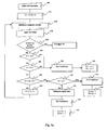
- Figures 6a and 6b are flow charts of a tuning procedure the direction of rotation of the motor generated by a control command.
- Fig. 7 is a flow chart of a procedure for defining a end position.
- the installation 1 shown in FIG. 1 comprises an actuator 10 for the operation of a movable element 7 for closing, occulting or solar protection such as for example a rolling shutter, a door or a store, or any type of mobile screen.
- This actuator 10 is powered by the power distribution network 5. It is connected to an interface user called the control box 2. It should also be noted that the network 5 can supply the actuator through the housing of control, as described for example in patent EP 0 822 315.
- the housing 2 comprises different keys. It includes, in particular, a key 3b allowing the user to control, by his actuation, an action of opening (or winding) of the element mobile 7 and a key 3a allowing the user to control, by its actuation, a closing action (or unwinding) of the movable element 7.
- the actuator 10 comprises a motor 6 and an electronic unit 4 of control of the power supply of this engine.
- the electronic unit 4 includes a logical processing unit such as a microcontroller to receive via an interface the electrical signals emitted by the control box and interpret them. It also includes briefs such as rewritable type for storing for example values representative of the end positions of the movable element and a value associating a direction of rotation of the motor with each of the keys 3a and 3b. It also includes meters and memories for store different timeout values, these delays being triggered following actions on the keys 3a and 3b and / or after the expiry of other delays.
- the unit electronics further comprises power components for the engine power supply. It includes controlled switches by the electronic unit and, depending on the type of engine used, it includes a voltage converter.
- the motor 6 allows the drive of the mobile element 7. It is therefore cinematically linked to it either directly or through a reducer.
- pressing the key of command 3a or the control key 3b for a period of time greater than the duration t1 of a delay T1 triggers the switching of a relay supplying the motor and, consequently, the rotation of the latter in the direction associated with the control key which has been activated.
- the timer T1 is triggered as soon as the the control key. It is represented by a bold line delimited by a rhombus of start of delay and a rhombus of end of delay.
- the relay returns to its original state, cutting off power to the motor as soon as the key is released.
- pressing the key during a duration less than the duration t1 of the delay T1 triggers as soon as the key is released a timer T2 called inhibition start.
- the electronic unit is inhibited, that is to say that the supports on the various keys of control of the box of control does not allow to control the rotation of the motor. he wait for the end of the inhibition period to be able to again control the rotation of the motor by pressing one of the keys of ordered.
- timer T2 triggers, for lack of support on one of the command keys during this timeout, the deadline for the inhibition period.
- a new press on one of the keys of order before expiry of the T2 expiry period extends the period muting and simultaneously triggers a timer T3 of one duration t3 and a timer T4 of duration t4. If the key is pressed for a duration less than the duration t3 or greater than the duration t4, the inhibition period ends when the key is released as shown in Figures 3 and 4. However, as shown in Figure 5, if the key is pressed for a duration greater than the duration t3 and less than the duration t4, the relaxation of the control key triggers a new T2 timer during which the inhibition period is prolonged.
- timers are used: a delay T1 for to discriminate a brief support of a prolonged support, a delay T2 of waiting and inhibition, time delays T3 and T4 for calibrating validation supports.
- configuration commands are issued and they cause configuration operations that are performed in the actuator.
- it can be a long-term recording of a operating parameter of the actuator, such as the value representative of an end position or as the relationship between the control keys and the movement directions of the actuator.
- the muting state is extended as long as the timers are relayed between them. As soon as the inhibition period expires, the delays possibly active are canceled and a new key press a duration greater than the duration t1 causes the activation of the motor.
- This first embodiment is more particularly intended for actuators whose electronic control unit is powered by permanently. If this is not the case (for example when the actuator is supplied via the control box), provision can be made for standby power of the electronic unit being effected for example by discharging a capacitor as a result of a particular command. We can then predict to impose a movement of a few seconds before any very brief support, this in order to charge the capacitor Power.
- a second embodiment of the method of operation of the actuator is more particularly intended for actuators whose unit electronics is not permanently powered but can may be suitable for other actuators.
- the first embodiment is not adapted to this type of actuator since the electronic unit can not measure the times while which it is not powered.
- This second embodiment therefore provides that the inhibition concerns at least the first command following a particular action.
- Each particular action causes a counter to be zeroed and each new key on one of the control keys, the duration of which is between the times t3 and t4, causes the incrementation of this counter.
- the end of the muting period is triggered when the counter reaches a predefined value.
- the so-called validation supports are calibrated, that is to say that their duration must be between the duration t3 and the duration t4 as schematically in Figures 3, 4 and 5.
- the sequences validation supports are very precise and will be difficult reproducible in an untimely way.
- the particular action can be a press on one of the keys of command of a duration less than the duration t1 beyond which a Engine control command is triggered.
- This particular action could also be a power up of the actuator or a double action type pressing the command keys simultaneously.
- Each validation press performed correctly can reset the inhibition period until the last support of the validation sequence configuration.
- the actuator In order to avoid a blockage caused by a short press untimely and during which it is not possible to order the actuator it is possible to choose, in the first inhibition period, inhibit only one direction of rotation, for example that corresponding to the control key on which was made a brief press having special support value. We then avoid blocking the command of the engine in the event that the user performs a brief brief by mistake in meaning while he wants to rotate the motor of the actuator in the other way. The inhibition delay is then cleared if the first pressing during the muting period is a key press controlling the rotation of the motor in the opposite direction to the direction controlled by the key on which the particular support was exercised.
- the support counter associated with the key controlling activation of the actuator in the opposite direction to the direction commanded by the key on which the particular support was performed can be incremented so that the sum of the values stored in the counters reaches a predefined value causing the end of the inhibition period.
- the actuator generates a return information such as for example by a slight movement of the element mobile to warn the installer or user performing operations configuration that these have been done. Preferably, this feedback will come during the last part of the validation sequence.
- the return information must be done while pressing one of the keys otherwise the actuator is not powered. In this case, the movement of the actuator is allowed, although it is done during the inhibition period. Indeed, it is not a response to a control order of the user, but a command order generated at the unit level engine control electronics.
- the short presses on the control buttons may not be considered for validating a position only to the extent that the position current is a particular position such as for example a position end of stroke or an intermediate position.
- the configuration phase can be marked by an indicator of configuration. If this indicator is active, ie if the device is partially or preferably, is completely configured, the supports on the control keys will immediately give rise to a movement of the moving element, unless it is in a particular position. In this case, it will be necessary to maintain the support during a duration greater than the predetermined duration t1 so that it is interpreted as a movement order. Support of a duration less than the predetermined duration t1 will be considered a signal setting the device configuration mode.
- the engine start is therefore necessarily delayed by the predetermined duration t1.
- a first step 100 the user brings the mobile element into high position.
- a validation sequence ( ⁇ ) which has the effect, in a step 120, of emptying the memory of the value associated with the current high end position, this value is then stored in a temporary memory.
- the use of timers of the order of the second allows easy reproduction by the user of the validation sequences. Of Moreover, the duration of the support necessary for the reproduction of these sequences make it virtually impossible for them to be inadvertently reproduced.
- a step 130 the user controls the rotation of the motor in one way or the other until the movable element reaches the new high end position chosen.
- the validation sequence ( ⁇ ) corresponds to a short press on the key 3b followed by two validation supports on the same key, the supports validation having a duration between t3 and t4.
- the number validation supports to modify the contents of the memory can also be different from two, especially greater than two to further secure the recorded values against maneuvers untimely.
- the commands of moving are done in the same way as the commands of moving out of the configuration sequence.
- the validation sequences of the different settings have all the same length. It can be expected, however, that some sequences (for example a sequence back to a configuration by default) are longer in the first execution mode of the process.
- the electronic control unit manages the reconfiguration of the position as previously described.
- the electronic control unit measure the duration of the support and restart a support counter maintained for a period between t3 and t4. If a number of supports is detected, a different configuration such as a configuration by fault is validated.
- a first step 200 the user briefly presses on one buttons on the control box. This action has the consequence to reset, in a step 210, two counters C1 and C2 associated respectively to the two control keys 3a and 3b of the housing of command and trigger, in a step 220, a period inhibition.
- a step 230 the user presses on a button of the control box. This support is tested at the level of a test step 240.
- the key is pressed on the same key as the key step 200, it is verified in steps 250 and 260 that its duration is greater than at the time t3 and less than the duration t4. If this is not the case, we end at the inhibition period at a step 290 and increment at one step 300, each of the counters C1 and C2 beyond a predefined value n. If this is the case, we verify in a test 270 that the sum of values stored in the counters is not greater than a value predefined. We then check at test level 310 whether the sum of values stored in the counters is equal to the preset value n.
- the inhibition period is ended in a step 330 and incremented, in a step 340, each of the counters C1 and C2 beyond the preset value n. If at the level of a test 310, the sum of the values stored in the meters is strictly greater than the value predefined n, the inhibition period is ended at a step 350 and increments, in a step 360, each of the counters C1 and C2 beyond of the predefined value n.
- step 370 If the result of the test 240 is negative, that is, if the support of step 230 is performed on another control key than that of step 200, in a step 370, the value of the counter C1 is tested. If its value is null, that is to say if there has been, between the brief support of step 200 and that of step 230, no validation support has allowed the incrementation of the counter C1 linked to the key actuated during step 200, we end the inhibition period in a step 430 and the command associated with the key actuated in a step 230 is executed in a step 440.
- the inhibition period is ended in a step 410 and incremented, in a step 420, each of the counters C1 and C2 beyond the preset value n.
- the simple counting of the number pulses on one or the other control button is insufficient to distinguish two sequences, such as for example aABA and aAAB, in which the characters a and A respectively designate supports short and long key 3a and the character B means a long press on the key 3b, a long press here having a duration between t3 and t4.
- an indicator or flag relating to each of the configurations pre-recorded This indicator is set high for all potentially valid configurations at a given moment considering support already done. As we move forward in the recognition process, some configurations are eliminated and the corresponding indicators go low. As soon as no indicator is no longer in the high state, one leaves the state of inhibition. We leave also of the inhibit state if only one indicator is in the high state, but in exploiting the information resulting from the valid sequence thus identified.
- the described operating method is of course also applicable by means of a specific programming tool, which allows reproduce the support sequences, while accurately calibrating the durations equivalent to the presses on the keys of the control box.
- sequences of special programming difficult to achieve from a housing can be combined with sequences such as those described in this application to achieve the entire programming process.
Landscapes
- Engineering & Computer Science (AREA)
- Structural Engineering (AREA)
- Architecture (AREA)
- Civil Engineering (AREA)
- Automation & Control Theory (AREA)
- General Physics & Mathematics (AREA)
- Physics & Mathematics (AREA)
- Power-Operated Mechanisms For Wings (AREA)
- Operating, Guiding And Securing Of Roll- Type Closing Members (AREA)
- Control Of Electric Motors In General (AREA)
- Lock And Its Accessories (AREA)
- Input From Keyboards Or The Like (AREA)
- Valve-Gear Or Valve Arrangements (AREA)
- Coating Apparatus (AREA)
Priority Applications (1)
| Application Number | Priority Date | Filing Date | Title |
|---|---|---|---|
| PL05007723T PL1586964T3 (pl) | 2004-04-09 | 2005-04-08 | Sposób działania napędu zasłony zwijanej oraz urządzenie do jego realizacji |
Applications Claiming Priority (4)
| Application Number | Priority Date | Filing Date | Title |
|---|---|---|---|
| FR0403739A FR2868862B1 (fr) | 2004-04-09 | 2004-04-09 | Procede de fonctionnement d'un actionneur de volet roulant et dispositif pour sa mise en oeuvre |
| FR0403739 | 2004-04-09 | ||
| FR0406284A FR2871508B1 (fr) | 2004-06-10 | 2004-06-10 | Procede de fonctionnement d'un volet roulant motorise commande par une telecommande a nombre de touches limite et dispositif pour sa mise en oeuvre |
| FR0406284 | 2004-06-10 |
Publications (3)
| Publication Number | Publication Date |
|---|---|
| EP1586964A2 true EP1586964A2 (de) | 2005-10-19 |
| EP1586964A3 EP1586964A3 (de) | 2006-04-12 |
| EP1586964B1 EP1586964B1 (de) | 2013-05-29 |
Family
ID=34934898
Family Applications (2)
| Application Number | Title | Priority Date | Filing Date |
|---|---|---|---|
| EP05007723.9A Expired - Lifetime EP1586964B1 (de) | 2004-04-09 | 2005-04-08 | Vorrichtung und Verfahren zum Betrieb des Aktuators eines Rollladens |
| EP05718392A Expired - Lifetime EP1756388B1 (de) | 2004-04-09 | 2005-04-08 | Betriebsverfahren für einen motorisierten rollladen und vorrichtung für dessen ausführung |
Family Applications After (1)
| Application Number | Title | Priority Date | Filing Date |
|---|---|---|---|
| EP05718392A Expired - Lifetime EP1756388B1 (de) | 2004-04-09 | 2005-04-08 | Betriebsverfahren für einen motorisierten rollladen und vorrichtung für dessen ausführung |
Country Status (9)
| Country | Link |
|---|---|
| US (2) | US7701160B2 (de) |
| EP (2) | EP1586964B1 (de) |
| JP (2) | JP5021178B2 (de) |
| CN (1) | CN1680681B (de) |
| AT (1) | ATE513975T1 (de) |
| CA (1) | CA2561268C (de) |
| ES (1) | ES2246196T3 (de) |
| PL (1) | PL1586964T3 (de) |
| WO (1) | WO2005098191A1 (de) |
Cited By (3)
| Publication number | Priority date | Publication date | Assignee | Title |
|---|---|---|---|---|
| FR2898221A1 (fr) * | 2006-03-06 | 2007-09-07 | Somfy Sas | Procede de commande et de test d'une installation domotique filaire |
| FR2910677A1 (fr) * | 2006-12-26 | 2008-06-27 | Somfy Sas | Capteur-emetteur de securite pour la detection de vent dans une installation domotique |
| FR3035234A1 (fr) * | 2015-04-15 | 2016-10-21 | Somfy Sas | Procede de commande en fonctionnement d'une installation domotique de fermeture ou de protection solaire et installation domotique associee |
Families Citing this family (4)
| Publication number | Priority date | Publication date | Assignee | Title |
|---|---|---|---|---|
| FR2892250B1 (fr) * | 2005-10-19 | 2008-01-11 | Somfy Sas | Procede de commande d'un actionneur de volet roulant |
| FR2925932B1 (fr) * | 2007-12-26 | 2011-08-26 | Somfy Sas | Procede de reglage d'une installation de protection solaire motorisee ne comprenant pas de butee franche. |
| CN107201874B (zh) * | 2017-05-26 | 2020-02-07 | 杭州正电科技有限公司 | 一种仓库卷帘门控制系统 |
| CN110109376B (zh) * | 2019-04-28 | 2022-03-15 | 九阳股份有限公司 | 一种处理烹饪器具按键顶死的控制方法 |
Family Cites Families (22)
| Publication number | Priority date | Publication date | Assignee | Title |
|---|---|---|---|---|
| US4872082A (en) * | 1987-09-02 | 1989-10-03 | Stanley Electronics | Door operator safety feature requiring constant actuation to close door |
| FR2654229B1 (fr) * | 1989-11-03 | 1996-08-09 | Simu | Procede et dispositif pour deplacer un element d'occultation jusqu'a des positions stables reglables et installation en faisant application. |
| FR2654299B3 (fr) | 1989-11-13 | 1992-04-03 | Crms | Dispositif de remplissage d'une tonne a lisier. |
| US5278480A (en) * | 1992-10-26 | 1994-01-11 | Stanley Home Automation | Door opener control with adaptive limits and method therefor |
| CN2185309Y (zh) * | 1993-12-06 | 1994-12-14 | 深圳求是科技开发有限公司 | 滑移门开门机的全自动控制器 |
| US5969637A (en) * | 1996-04-24 | 1999-10-19 | The Chamberlain Group, Inc. | Garage door opener with light control |
| DE29620199U1 (de) * | 1996-05-06 | 1997-09-04 | Jauch + Schmid, Uhren- und Apparatefabrik GmbH und Co, 78054 Villingen-Schwenningen | Intelligenter Rolladenschalter |
| DE19654387A1 (de) * | 1996-05-06 | 1997-11-13 | Jauch & Schmid Uhren Und Appar | Verfahren zur Steuerung von Verdunkelungsvorrichtungen |
| DE19630491C1 (de) | 1996-07-29 | 1998-02-05 | Selve Ernst Gmbh Co Kg | Schaltungsanordnung zur Steuerung von elektromotorischen Antrieben für auf- und abwickelbare Behänge |
| US5760557A (en) * | 1996-12-19 | 1998-06-02 | Odegaard; John I. | Variable interval control device |
| US5929580A (en) * | 1997-08-05 | 1999-07-27 | Wayne-Dalton Corp. | System and related methods for detecting an obstruction in the path of a garage door controlled by an open-loop operator |
| CA2269001C (en) * | 1998-04-21 | 2008-07-15 | The Chamberlain Group, Inc. | Controller for a door operator |
| US6078159A (en) * | 1999-02-17 | 2000-06-20 | The Chamberlain Group, Inc. | Method and apparatus for programming a logic board from switching power |
| JP3595932B2 (ja) * | 1999-07-29 | 2004-12-02 | 三和シヤッター工業株式会社 | 建築用電動シャッターの制御装置 |
| FR2802007B3 (fr) * | 1999-12-07 | 2002-02-15 | Prigent O Meara Erven | Systeme de commande a distance pour volets electriques ou equivalents fonctionnels |
| CN2455914Y (zh) * | 2000-12-26 | 2001-10-24 | 卢再益 | 卷门马达的遥控电路装置 |
| US6751909B2 (en) * | 2001-02-06 | 2004-06-22 | The Stanley Works | Automatic door control system |
| FR2832451B1 (fr) * | 2001-11-22 | 2004-02-27 | Somfy | Procede de mise en conformite avec l'ordre donne du sens d'un moteur electrique dans une installation d'occultation ou similaire tel que fermeture |
| US6759822B2 (en) * | 2001-12-20 | 2004-07-06 | Southern Illinois University | Methods and apparatus to improve the performance of universal electric motors |
| FR2839561B1 (fr) * | 2002-05-13 | 2004-07-30 | Somfy | Procede d'apprentissage des fins de course d'un actionneur de volet roulant |
| US7023162B2 (en) * | 2003-02-18 | 2006-04-04 | The Chamberlain Group, Inc. | Automatic gate operator |
| US7183732B2 (en) * | 2004-04-22 | 2007-02-27 | Wayne-Dalton Corp. | Motorized barrier operator system for controlling a stopped, partially open barrier and related methods |
-
2005
- 2005-04-08 PL PL05007723T patent/PL1586964T3/pl unknown
- 2005-04-08 EP EP05007723.9A patent/EP1586964B1/de not_active Expired - Lifetime
- 2005-04-08 CN CN2005100651022A patent/CN1680681B/zh not_active Expired - Lifetime
- 2005-04-08 JP JP2005111906A patent/JP5021178B2/ja not_active Expired - Fee Related
- 2005-04-08 JP JP2007506862A patent/JP5112855B2/ja not_active Expired - Fee Related
- 2005-04-08 AT AT05718392T patent/ATE513975T1/de not_active IP Right Cessation
- 2005-04-08 WO PCT/IB2005/000922 patent/WO2005098191A1/fr not_active Ceased
- 2005-04-08 CA CA2561268A patent/CA2561268C/en not_active Expired - Fee Related
- 2005-04-08 ES ES05007723T patent/ES2246196T3/es not_active Expired - Lifetime
- 2005-04-08 US US11/547,250 patent/US7701160B2/en not_active Expired - Fee Related
- 2005-04-08 EP EP05718392A patent/EP1756388B1/de not_active Expired - Lifetime
- 2005-04-08 US US11/102,526 patent/US20050242763A1/en not_active Abandoned
Cited By (7)
| Publication number | Priority date | Publication date | Assignee | Title |
|---|---|---|---|---|
| FR2898221A1 (fr) * | 2006-03-06 | 2007-09-07 | Somfy Sas | Procede de commande et de test d'une installation domotique filaire |
| EP1843229A3 (de) * | 2006-03-06 | 2009-01-07 | Somfy SAS | Verfahren zur Bedienung und zum Testen einer verdrahteten Heiminstallation |
| FR2910677A1 (fr) * | 2006-12-26 | 2008-06-27 | Somfy Sas | Capteur-emetteur de securite pour la detection de vent dans une installation domotique |
| EP1939832A1 (de) * | 2006-12-26 | 2008-07-02 | Somfy SAS | Sicherheitssensor und -sender zum Detektieren von Wind in einer Hausanlage |
| US7729807B2 (en) | 2006-12-26 | 2010-06-01 | Somfy Sas | Security sensor-transmitter for detecting wind in a home automation installation |
| CN101211499B (zh) * | 2006-12-26 | 2011-12-28 | Somfy两合公司 | 用于检测家庭自动设备上的风的安全传感器-发送器 |
| FR3035234A1 (fr) * | 2015-04-15 | 2016-10-21 | Somfy Sas | Procede de commande en fonctionnement d'une installation domotique de fermeture ou de protection solaire et installation domotique associee |
Also Published As
| Publication number | Publication date |
|---|---|
| JP2007532802A (ja) | 2007-11-15 |
| PL1586964T3 (pl) | 2013-10-31 |
| CN1680681A (zh) | 2005-10-12 |
| WO2005098191A1 (fr) | 2005-10-20 |
| US20050242763A1 (en) | 2005-11-03 |
| EP1586964B1 (de) | 2013-05-29 |
| JP2005299384A (ja) | 2005-10-27 |
| US20070261802A1 (en) | 2007-11-15 |
| CN1680681B (zh) | 2012-05-30 |
| CA2561268C (en) | 2012-09-04 |
| JP5021178B2 (ja) | 2012-09-05 |
| ATE513975T1 (de) | 2011-07-15 |
| EP1756388A1 (de) | 2007-02-28 |
| EP1586964A3 (de) | 2006-04-12 |
| ES2246196T3 (es) | 2013-10-21 |
| JP5112855B2 (ja) | 2013-01-09 |
| CA2561268A1 (en) | 2005-10-20 |
| ES2246196T1 (es) | 2006-02-16 |
| EP1756388B1 (de) | 2011-06-22 |
| US7701160B2 (en) | 2010-04-20 |
Similar Documents
| Publication | Publication Date | Title |
|---|---|---|
| EP1626154B1 (de) | Verfahren zum Betrieb eines aus einer Drahtschnittstelle gesteuerten und versorgten Rollladens | |
| EP0426577B1 (de) | Verfahren und Vorrichtung zum Verstellen einer Verdunkelungsanordnung in justierbaren Positionen und Installation zur Durchführung der Anmeldung | |
| EP2009527B1 (de) | Konfigurationsverfahren eines Antriebssystems eines Verschlussschirms, der als Sonnenschutz oder Projektionsschirm fungieren kann | |
| CH666720A5 (fr) | Dispositif de commande pour volet roulant ou similaire a lames orientables. | |
| EP1510649B1 (de) | Verfahren zur Initialisierung eines Rollladens | |
| EP0311477B1 (de) | Verfahren zur Dehnung eines analogen Signals und Vorrichtung zur Implementierung des Verfahrens | |
| EP1659252B1 (de) | Verfahren zur Steuerung einer motorisierten Verschlussvorrichtung und motorisierte Verschlussvorrichtung mit Hardware und Software um dieses Verfahren auszuführen | |
| EP1586964B1 (de) | Vorrichtung und Verfahren zum Betrieb des Aktuators eines Rollladens | |
| EP2075401A1 (de) | Method of adjusting a motorised solar protection installation not comprising an end-stop | |
| EP0517650A1 (de) | Schaltungsanordnung zur automatischen Steuerung der Beleuchtungsstärke in einem Raum | |
| FR3088362A1 (fr) | Procede de commande en fonctionnement d'une installation domotique de fermeture, d'occultation ou de protection solaire et installation domotique associee | |
| EP1541798B1 (de) | Lernverfahren für einen motorisierten Verschluss und und Vorrichtung zur Ausführung dieses Verfahrens | |
| EP1998239B1 (de) | Verfahren zur Konfiguration einer Steuereinheit eines Hausleitsystemes | |
| EP1160415B1 (de) | Steuerung für motorisierte Verdunkelungsvorrichtungen mit Programmwahl | |
| FR2771521A1 (fr) | Dispositif de commande d'un moyen de protection solaire motorise | |
| EP3312689B1 (de) | Verfahren zur betriebssteuerung einer domotik-anlage, und entsprechende domotik-anlage | |
| FR2884280A1 (fr) | Appareil de configuration d'un volet roulant motorise et procede de fabrication et de fonctionnement d'un tel appareil | |
| EP1154120A1 (de) | Steuerung für motorgetriebene Verdunkelungssysteme mit perfektionierter Endabschaltung | |
| FR2871508A1 (fr) | Procede de fonctionnement d'un volet roulant motorise commande par une telecommande a nombre de touches limite et dispositif pour sa mise en oeuvre | |
| FR3035234B1 (fr) | Procede de commande en fonctionnement d'une installation domotique de fermeture ou de protection solaire et installation domotique associee | |
| EP1154121A1 (de) | Perfektionerte Steuerung für motorgetriebene Verdunkelungsvorrichtungen | |
| WO2003081358A1 (fr) | Procede de commande d'un volet roulant ou similaire | |
| EP1662845B1 (de) | Verfahren zur Programmierung der Verzögerungsdauer eines Zeitschalters | |
| WO2024208985A1 (fr) | Procédé de configuration d'une installation domotique. | |
| EP2098935A2 (de) | Motor mit elektronischer Steuerung der Endschalter und Einbauverfahren einer Öffnungs- und Schließvorrichtung, wie insbesondere für ein Rollo, das einen solchen Motor umfasst |
Legal Events
| Date | Code | Title | Description |
|---|---|---|---|
| PUAI | Public reference made under article 153(3) epc to a published international application that has entered the european phase |
Free format text: ORIGINAL CODE: 0009012 |
|
| AK | Designated contracting states |
Kind code of ref document: A2 Designated state(s): AT BE BG CH CY CZ DE DK EE ES FI FR GB GR HU IE IS IT LI LT LU MC NL PL PT RO SE SI SK TR |
|
| AX | Request for extension of the european patent |
Extension state: AL BA HR LV MK YU |
|
| RIN1 | Information on inventor provided before grant (corrected) |
Inventor name: GREHANT, BERNARD Inventor name: VIOLLAND, PAUL Inventor name: FROIDURE, CYRILLE Inventor name: MAISTRE, VALERIE |
|
| PUAL | Search report despatched |
Free format text: ORIGINAL CODE: 0009013 |
|
| AK | Designated contracting states |
Kind code of ref document: A3 Designated state(s): AT BE BG CH CY CZ DE DK EE ES FI FR GB GR HU IE IS IT LI LT LU MC NL PL PT RO SE SI SK TR |
|
| AX | Request for extension of the european patent |
Extension state: AL BA HR LV MK YU |
|
| 17P | Request for examination filed |
Effective date: 20060921 |
|
| AKX | Designation fees paid |
Designated state(s): AT BE BG CH CY CZ DE DK EE ES FI FR GB GR HU IE IS IT LI LT LU MC NL PL PT RO SE SI SK TR |
|
| 17Q | First examination report despatched |
Effective date: 20070118 |
|
| GRAP | Despatch of communication of intention to grant a patent |
Free format text: ORIGINAL CODE: EPIDOSNIGR1 |
|
| GRAS | Grant fee paid |
Free format text: ORIGINAL CODE: EPIDOSNIGR3 |
|
| GRAA | (expected) grant |
Free format text: ORIGINAL CODE: 0009210 |
|
| AK | Designated contracting states |
Kind code of ref document: B1 Designated state(s): AT BE BG CH CY CZ DE DK EE ES FI FR GB GR HU IE IS IT LI LT LU MC NL PL PT RO SE SI SK TR |
|
| REG | Reference to a national code |
Ref country code: GB Ref legal event code: FG4D Free format text: NOT ENGLISH |
|
| REG | Reference to a national code |
Ref country code: CH Ref legal event code: EP |
|
| REG | Reference to a national code |
Ref country code: AT Ref legal event code: REF Ref document number: 614775 Country of ref document: AT Kind code of ref document: T Effective date: 20130615 |
|
| REG | Reference to a national code |
Ref country code: IE Ref legal event code: FG4D Free format text: LANGUAGE OF EP DOCUMENT: FRENCH |
|
| REG | Reference to a national code |
Ref country code: DE Ref legal event code: R096 Ref document number: 602005039769 Country of ref document: DE Effective date: 20130725 |
|
| REG | Reference to a national code |
Ref country code: CH Ref legal event code: NV Representative=s name: BUGNION S.A., CH |
|
| REG | Reference to a national code |
Ref country code: NL Ref legal event code: T3 |
|
| REG | Reference to a national code |
Ref country code: AT Ref legal event code: MK05 Ref document number: 614775 Country of ref document: AT Kind code of ref document: T Effective date: 20130529 |
|
| REG | Reference to a national code |
Ref country code: GR Ref legal event code: EP Ref document number: 20130401725 Country of ref document: GR Effective date: 20130920 |
|
| REG | Reference to a national code |
Ref country code: ES Ref legal event code: FG2A Ref document number: 2246196 Country of ref document: ES Kind code of ref document: T3 Effective date: 20131021 |
|
| REG | Reference to a national code |
Ref country code: LT Ref legal event code: MG4D |
|
| PG25 | Lapsed in a contracting state [announced via postgrant information from national office to epo] |
Ref country code: IS Free format text: LAPSE BECAUSE OF FAILURE TO SUBMIT A TRANSLATION OF THE DESCRIPTION OR TO PAY THE FEE WITHIN THE PRESCRIBED TIME-LIMIT Effective date: 20130929 Ref country code: LT Free format text: LAPSE BECAUSE OF FAILURE TO SUBMIT A TRANSLATION OF THE DESCRIPTION OR TO PAY THE FEE WITHIN THE PRESCRIBED TIME-LIMIT Effective date: 20130529 Ref country code: PT Free format text: LAPSE BECAUSE OF FAILURE TO SUBMIT A TRANSLATION OF THE DESCRIPTION OR TO PAY THE FEE WITHIN THE PRESCRIBED TIME-LIMIT Effective date: 20130930 Ref country code: AT Free format text: LAPSE BECAUSE OF FAILURE TO SUBMIT A TRANSLATION OF THE DESCRIPTION OR TO PAY THE FEE WITHIN THE PRESCRIBED TIME-LIMIT Effective date: 20130529 Ref country code: SE Free format text: LAPSE BECAUSE OF FAILURE TO SUBMIT A TRANSLATION OF THE DESCRIPTION OR TO PAY THE FEE WITHIN THE PRESCRIBED TIME-LIMIT Effective date: 20130529 Ref country code: SI Free format text: LAPSE BECAUSE OF FAILURE TO SUBMIT A TRANSLATION OF THE DESCRIPTION OR TO PAY THE FEE WITHIN THE PRESCRIBED TIME-LIMIT Effective date: 20130529 Ref country code: FI Free format text: LAPSE BECAUSE OF FAILURE TO SUBMIT A TRANSLATION OF THE DESCRIPTION OR TO PAY THE FEE WITHIN THE PRESCRIBED TIME-LIMIT Effective date: 20130529 |
|
| REG | Reference to a national code |
Ref country code: PL Ref legal event code: T3 |
|
| PG25 | Lapsed in a contracting state [announced via postgrant information from national office to epo] |
Ref country code: BG Free format text: LAPSE BECAUSE OF FAILURE TO SUBMIT A TRANSLATION OF THE DESCRIPTION OR TO PAY THE FEE WITHIN THE PRESCRIBED TIME-LIMIT Effective date: 20130829 |
|
| PG25 | Lapsed in a contracting state [announced via postgrant information from national office to epo] |
Ref country code: SK Free format text: LAPSE BECAUSE OF FAILURE TO SUBMIT A TRANSLATION OF THE DESCRIPTION OR TO PAY THE FEE WITHIN THE PRESCRIBED TIME-LIMIT Effective date: 20130529 Ref country code: CZ Free format text: LAPSE BECAUSE OF FAILURE TO SUBMIT A TRANSLATION OF THE DESCRIPTION OR TO PAY THE FEE WITHIN THE PRESCRIBED TIME-LIMIT Effective date: 20130529 Ref country code: DK Free format text: LAPSE BECAUSE OF FAILURE TO SUBMIT A TRANSLATION OF THE DESCRIPTION OR TO PAY THE FEE WITHIN THE PRESCRIBED TIME-LIMIT Effective date: 20130529 Ref country code: EE Free format text: LAPSE BECAUSE OF FAILURE TO SUBMIT A TRANSLATION OF THE DESCRIPTION OR TO PAY THE FEE WITHIN THE PRESCRIBED TIME-LIMIT Effective date: 20130529 |
|
| PG25 | Lapsed in a contracting state [announced via postgrant information from national office to epo] |
Ref country code: RO Free format text: LAPSE BECAUSE OF FAILURE TO SUBMIT A TRANSLATION OF THE DESCRIPTION OR TO PAY THE FEE WITHIN THE PRESCRIBED TIME-LIMIT Effective date: 20130529 |
|
| PLBE | No opposition filed within time limit |
Free format text: ORIGINAL CODE: 0009261 |
|
| STAA | Information on the status of an ep patent application or granted ep patent |
Free format text: STATUS: NO OPPOSITION FILED WITHIN TIME LIMIT |
|
| 26N | No opposition filed |
Effective date: 20140303 |
|
| REG | Reference to a national code |
Ref country code: DE Ref legal event code: R097 Ref document number: 602005039769 Country of ref document: DE Effective date: 20140303 |
|
| PG25 | Lapsed in a contracting state [announced via postgrant information from national office to epo] |
Ref country code: MC Free format text: LAPSE BECAUSE OF FAILURE TO SUBMIT A TRANSLATION OF THE DESCRIPTION OR TO PAY THE FEE WITHIN THE PRESCRIBED TIME-LIMIT Effective date: 20130529 Ref country code: LU Free format text: LAPSE BECAUSE OF FAILURE TO SUBMIT A TRANSLATION OF THE DESCRIPTION OR TO PAY THE FEE WITHIN THE PRESCRIBED TIME-LIMIT Effective date: 20140408 |
|
| GBPC | Gb: european patent ceased through non-payment of renewal fee |
Effective date: 20140408 |
|
| REG | Reference to a national code |
Ref country code: IE Ref legal event code: MM4A |
|
| PG25 | Lapsed in a contracting state [announced via postgrant information from national office to epo] |
Ref country code: GB Free format text: LAPSE BECAUSE OF NON-PAYMENT OF DUE FEES Effective date: 20140408 |
|
| PG25 | Lapsed in a contracting state [announced via postgrant information from national office to epo] |
Ref country code: IE Free format text: LAPSE BECAUSE OF NON-PAYMENT OF DUE FEES Effective date: 20140408 |
|
| REG | Reference to a national code |
Ref country code: FR Ref legal event code: PLFP Year of fee payment: 12 |
|
| PG25 | Lapsed in a contracting state [announced via postgrant information from national office to epo] |
Ref country code: CY Free format text: LAPSE BECAUSE OF FAILURE TO SUBMIT A TRANSLATION OF THE DESCRIPTION OR TO PAY THE FEE WITHIN THE PRESCRIBED TIME-LIMIT Effective date: 20130529 |
|
| PG25 | Lapsed in a contracting state [announced via postgrant information from national office to epo] |
Ref country code: HU Free format text: LAPSE BECAUSE OF FAILURE TO SUBMIT A TRANSLATION OF THE DESCRIPTION OR TO PAY THE FEE WITHIN THE PRESCRIBED TIME-LIMIT; INVALID AB INITIO Effective date: 20050408 |
|
| REG | Reference to a national code |
Ref country code: DE Ref legal event code: R082 Ref document number: 602005039769 Country of ref document: DE |
|
| REG | Reference to a national code |
Ref country code: FR Ref legal event code: PLFP Year of fee payment: 13 |
|
| REG | Reference to a national code |
Ref country code: FR Ref legal event code: PLFP Year of fee payment: 14 |
|
| REG | Reference to a national code |
Ref country code: DE Ref legal event code: R081 Ref document number: 602005039769 Country of ref document: DE Owner name: SOMFY ACTIVITES SA, FR Free format text: FORMER OWNER: SOMFY SAS, CLUSES, FR |
|
| PGFP | Annual fee paid to national office [announced via postgrant information from national office to epo] |
Ref country code: CH Payment date: 20220329 Year of fee payment: 18 |
|
| PGFP | Annual fee paid to national office [announced via postgrant information from national office to epo] |
Ref country code: TR Payment date: 20220328 Year of fee payment: 18 Ref country code: GR Payment date: 20220317 Year of fee payment: 18 |
|
| PGFP | Annual fee paid to national office [announced via postgrant information from national office to epo] |
Ref country code: ES Payment date: 20220503 Year of fee payment: 18 |
|
| REG | Reference to a national code |
Ref country code: CH Ref legal event code: PL |
|
| PG25 | Lapsed in a contracting state [announced via postgrant information from national office to epo] |
Ref country code: GR Free format text: LAPSE BECAUSE OF NON-PAYMENT OF DUE FEES Effective date: 20231110 |
|
| PG25 | Lapsed in a contracting state [announced via postgrant information from national office to epo] |
Ref country code: LI Free format text: LAPSE BECAUSE OF NON-PAYMENT OF DUE FEES Effective date: 20230430 Ref country code: GR Free format text: LAPSE BECAUSE OF NON-PAYMENT OF DUE FEES Effective date: 20231110 Ref country code: CH Free format text: LAPSE BECAUSE OF NON-PAYMENT OF DUE FEES Effective date: 20230430 |
|
| PGFP | Annual fee paid to national office [announced via postgrant information from national office to epo] |
Ref country code: NL Payment date: 20240325 Year of fee payment: 20 |
|
| REG | Reference to a national code |
Ref country code: ES Ref legal event code: FD2A Effective date: 20240527 |
|
| PGFP | Annual fee paid to national office [announced via postgrant information from national office to epo] |
Ref country code: PL Payment date: 20240319 Year of fee payment: 20 Ref country code: FR Payment date: 20240308 Year of fee payment: 20 |
|
| PGFP | Annual fee paid to national office [announced via postgrant information from national office to epo] |
Ref country code: DE Payment date: 20240327 Year of fee payment: 20 |
|
| PG25 | Lapsed in a contracting state [announced via postgrant information from national office to epo] |
Ref country code: ES Free format text: LAPSE BECAUSE OF NON-PAYMENT OF DUE FEES Effective date: 20230409 |
|
| PG25 | Lapsed in a contracting state [announced via postgrant information from national office to epo] |
Ref country code: ES Free format text: LAPSE BECAUSE OF NON-PAYMENT OF DUE FEES Effective date: 20230409 |
|
| PGFP | Annual fee paid to national office [announced via postgrant information from national office to epo] |
Ref country code: IT Payment date: 20240411 Year of fee payment: 20 |
|
| PGFP | Annual fee paid to national office [announced via postgrant information from national office to epo] |
Ref country code: BE Payment date: 20240415 Year of fee payment: 20 |
|
| REG | Reference to a national code |
Ref country code: DE Ref legal event code: R071 Ref document number: 602005039769 Country of ref document: DE |
|
| REG | Reference to a national code |
Ref country code: NL Ref legal event code: MK Effective date: 20250407 |
|
| REG | Reference to a national code |
Ref country code: BE Ref legal event code: MK Effective date: 20250408 |