EP1587043A2 - Dispositif de communication et câble de communication - Google Patents
Dispositif de communication et câble de communication Download PDFInfo
- Publication number
- EP1587043A2 EP1587043A2 EP05006810A EP05006810A EP1587043A2 EP 1587043 A2 EP1587043 A2 EP 1587043A2 EP 05006810 A EP05006810 A EP 05006810A EP 05006810 A EP05006810 A EP 05006810A EP 1587043 A2 EP1587043 A2 EP 1587043A2
- Authority
- EP
- European Patent Office
- Prior art keywords
- communication
- converting
- command
- central control
- control unit
- Prior art date
- Legal status (The legal status is an assumption and is not a legal conclusion. Google has not performed a legal analysis and makes no representation as to the accuracy of the status listed.)
- Withdrawn
Links
- 238000004891 communication Methods 0.000 title claims abstract description 205
- 238000006243 chemical reaction Methods 0.000 claims description 46
- 238000000034 method Methods 0.000 claims description 6
- 230000002093 peripheral effect Effects 0.000 abstract description 40
- 238000012545 processing Methods 0.000 description 22
- 238000001356 surgical procedure Methods 0.000 description 8
- 206010002091 Anaesthesia Diseases 0.000 description 7
- 230000037005 anaesthesia Effects 0.000 description 7
- 230000003068 static effect Effects 0.000 description 6
- 210000002784 stomach Anatomy 0.000 description 5
- 238000010276 construction Methods 0.000 description 3
- 230000008901 benefit Effects 0.000 description 2
- 238000012986 modification Methods 0.000 description 2
- 230000004048 modification Effects 0.000 description 2
- 230000005540 biological transmission Effects 0.000 description 1
- 238000011161 development Methods 0.000 description 1
- 230000018109 developmental process Effects 0.000 description 1
- 238000010586 diagram Methods 0.000 description 1
- 230000000694 effects Effects 0.000 description 1
- 238000005516 engineering process Methods 0.000 description 1
- 230000006870 function Effects 0.000 description 1
- 230000003902 lesion Effects 0.000 description 1
Images


Classifications
-
- A—HUMAN NECESSITIES
- A61—MEDICAL OR VETERINARY SCIENCE; HYGIENE
- A61B—DIAGNOSIS; SURGERY; IDENTIFICATION
- A61B1/00—Instruments for performing medical examinations of the interior of cavities or tubes of the body by visual or photographical inspection, e.g. endoscopes; Illuminating arrangements therefor
- A61B1/00002—Operational features of endoscopes
- A61B1/00004—Operational features of endoscopes characterised by electronic signal processing
- A61B1/00006—Operational features of endoscopes characterised by electronic signal processing of control signals
-
- A—HUMAN NECESSITIES
- A61—MEDICAL OR VETERINARY SCIENCE; HYGIENE
- A61B—DIAGNOSIS; SURGERY; IDENTIFICATION
- A61B1/00—Instruments for performing medical examinations of the interior of cavities or tubes of the body by visual or photographical inspection, e.g. endoscopes; Illuminating arrangements therefor
- A61B1/00002—Operational features of endoscopes
- A61B1/00011—Operational features of endoscopes characterised by signal transmission
- A61B1/00018—Operational features of endoscopes characterised by signal transmission using electrical cables
-
- A—HUMAN NECESSITIES
- A61—MEDICAL OR VETERINARY SCIENCE; HYGIENE
- A61B—DIAGNOSIS; SURGERY; IDENTIFICATION
- A61B2560/00—Constructional details of operational features of apparatus; Accessories for medical measuring apparatus
- A61B2560/04—Constructional details of apparatus
- A61B2560/0443—Modular apparatus
- A61B2560/045—Modular apparatus with a separable interface unit, e.g. for communication
Definitions
- This invention relates to a communication device for effecting communication between a central control unit and an object appliance.
- medical treatment appliances include electric scalpel instruments, ultrasonic suction devices, laser scalpel instruments and others. Although these medical treatment appliances are sometimes used on their own, they are also often used as part of a larger medical treatment system. Using these medical treatment appliances, a surgeon holds a surgical implement such as an electric scalpel in a hand to treat a lesion of an afflicted area or the like.
- This kind of medical treatment system has a central control unit capable of controlling the operations of multiple medical treatment appliances such as an electric scalpel device, a stomach-inflating device, and a camera device by means of remote control units such as foot switches, hand switches and remote controllers.
- a central control unit capable of controlling the operations of multiple medical treatment appliances such as an electric scalpel device, a stomach-inflating device, and a camera device by means of remote control units such as foot switches, hand switches and remote controllers.
- the central control unit selectively displays a desired medical treatment appliance, for example selected by operation of a remote control unit on a display part such as a monitor so that the respective medical treatment appliance can be easily recognized. Then, the central control unit centrally controls the medical device selectively displayed on the display part on the basis of user manipulations of the remote control units.
- peripheral appliances such as anesthesia unit systems made up of electrocardiograms and anesthesia units, and beds and lights and so on
- peripheral appliances such as anesthesia unit systems, beds and lights have been individually controlled.
- brightness control and so on have been carried out by a nurse using a remote controller (not shown).
- communication devices used for communication between appliances include for example those proposed in JP-UM-A-4-135044 and JP-A-8-51471.
- a communication device set forth in JP-A-8-51471, on the other hand, is constructed to convert communication data input through a first interface with a predetermined interface agreement and output to a second interface.
- a central control unit for stomach-inflators and cameras and so on can not control peripheral appliances that use different forms of communication (e.g., the above-mentioned anesthesia unit system, bed, lights, etc.).
- the present invention was made in view of these points, and it is an object of the invention to provide a communication device which makes communication between a central control unit and an appliance possible and thereby makes central control of the appliance possible, even if their forms of communication are different.
- a communication path for example a communication cable or a communication device
- a converting part for converting a communication command from the central control unit into a communication command for the appliance.
- a communication command is a transmitted command.
- An output switching part for switching the communication commands converted by the converting part in correspondence with the object appliance can be further provided.
- multiple appliances can be handled by one type of communication device or communication cable.
- a communication device can have a storing part for storing data relating communication commands to be converted by the converting part, and the converting part converts preset communication commands output from the central control unit in correspondence with the object appliance on the basis of the data relating to the communication commands stored in the storing part.
- data conversion details can be easily changed by a data change.
- the converting part may carry out conversion between forms of communication using different numbers of signal lines. And, the converting part may carry out conversion between parallel communication and serial communication.
- a communication device has the effect of making communication between a central control unit and an appliance possible and thereby making central control of the appliance possible, even if their forms of communication are different.
- the invention is applied to an endoscope surgery system.
- the endoscope surgery system is given by way of example only and not to limit the scope or spirit of the invention.
- an endoscope surgery system has a rigid endoscope (hereinafter simply endoscope) 2 fitted with a TV camera 1 incorporating an image pick-up device.
- This endoscope 2 is inserted through a trocar (not shown) into the stomach cavity of a patient 3 lying on an operating table as is known in the art.
- a stomach-inflating trocar 4 for inflating the stomach and an operating appliance trocar 6 for guiding an electric scalpel 5, which is an operating appliance, into the stomach cavity are also inserted into the patient 3.
- a signal cable 1a connected to the TV camera 1, a light guide cable 2a connected to the endoscope 2, a stomach-inflating tube 4a connected to the stomach-inflating trocar 4, and a signal cable 5a connected to the electric scalpel 5 are respectively connected to a CCU (Communication Control Unit) 11, a light source 12, an inflator 13, and an electric scalpel device 14.
- CCU Common Control Unit
- the CCU 11 performs signal processing with respect to the image pick-up device built into the TV camera 1, and displays an endoscope image on a monitor 10.
- the light source 12 supplies illuminating light to the endoscope 2.
- the inflator 13 supplies air or other gas for stomach inflation to the stomach cavity of the patient 3 through the stomach-inflating trocar 4.
- the electric scalpel device 14 supplies highfrequency electric power for cauterization to the electric scalpel 5.
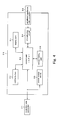
- the CCU 11, the light source 12, the inflator 13 and the electric scalpel device 14 are centrally controlled by a system controller 15 serving as a central control unit.
- the endoscope surgery system also includes peripheral appliances 19 such as an HDD recorder 16 for recording the image signal output from the CCU 11 and a light 17 constituting a lighting device for illuminating the operating theater.
- the system controller 15 is for example capable of 7-line serial and 3-line parallel communication only. Accordingly, it can control medical devices compatible with 7-line serial and 3-line parallel communication with ordinary communication cables as communication devices.
- Medical treatment appliances such as the CCU 11, the light source 12, the stomach-inflator 13 and the electric scalpel 14 are capable of 7-line serial communication, and these are connected to the system controller 15 by RS232C cables 18 used for this form of communication and are controllable by common 7-line serial communication.
- the HDD recorder 16 and the light 17 and other peripheral appliances 19 employ forms of communication different from the 7-line serial and 3-line parallel communication handled by the system controller 15.
- the HDD recorder 16 employs 4-line parallel communication and the light 17 employs 3-line serial communication.
- the HDD recorder 16 and the light 17 and other peripheral appliances 19 have been separately controlled. For example, static image capture with the HDD recorder 16 and brightness adjustment of the light 17 and so on have been carried out by a nurse using an independent remote controller (not shown).
- peripheral appliances 19 having different forms of communication such as the HDD recorder 16 and the light 17 are connected to the system controller 15 and centrally controlled.
- the HDD recorder 16 and the light 17 are each connected to the system controller 15 by a communication cable 20 constituting a communication device.
- the communication cable 20 is made up of a controller side connector 21 serving as an input part, a parallel cable 22, a circuit board 23, and a peripheral appliance side connector 24 serving as an output part.
- the controller-side connector 21 is connected to a connector socket 15a provided on the system controller 15.
- the parallel cable 22 extends from the controller-side connector 21 and is electrically connected to the circuit board 23.
- This parallel cable 22 is a for example 3-line parallel communication cable, by which communication with the system controller 15 is possible.
- the circuit board 23 carries a CPU for executing command conversion processing on communication commands from the system controller 15 in correspondence with a peripheral appliance.
- This circuit board 23 for example carries out command conversion processing in correspondence with a peripheral appliance to convert 3-line parallel communication to 4-line parallel communication or 3-line serial communication.
- the above-mentioned peripheral appliance side connector 24 is electrically connected to the circuit board 23.
- This peripheral appliance side connector 24 is connected to a connector socket 16a, 17a provided in the HDD recorder 16, light 17 or other peripheral appliance 19.
- the circuit board 23 is housed in a case 25, and the peripheral appliance side connector 24 projects from this case 25.
- a display part 31 and a setting button 32 are provided on the case 25.
- the display part 31 displays the name of the peripheral appliance with respect to which communication command conversion processing is being carried out.
- the display part 31 shown in Fig. 3 is an LED display and displays the device name in digits, but alternatively it may be an LCD or some other display and may display the device name in letters.
- the setting button 32 is a button for performing a setting operation for communication command conversion processing. When this setting button 32 is pressed steadily it goes into a setting mode, and a setting operation, which will be discussed later, becomes possible.
- the setting button 32 and the display part 31 are mounted on the circuit board 23.
- a control part 33 serving as a converting part, an input/output selecting circuit 34 serving as an output switching part, a power supply circuit 35, and a settings storing part 36 serving as a storing part are also mounted on this circuit board 23.
- the control part 33 includes for example a CPU (Central Processing Unit), and performs communication command conversion processing for converting communication commands in correspondence with the respective peripheral appliance.
- CPU Central Processing Unit
- the input/output selecting circuit 34 switches communication commands converted by the control part 33 to correspond with a respective peripheral appliance 19. This input/output selecting circuit 34 also selects whether a signal from the system controller 15 is output to the peripheral appliance 19 or a signal from the peripheral appliance 19 is input to the system controller 15.
- the settings storing part 36 stores as conversion data for converting input communication commands for example as a command conversion table, which will be further discussed later.
- the settings storing part 36 is made up of electrically erasable (rewriteable) ROM such as for example EEPROM (Electrically Erasable Programmable Read-Only Memory).
- the power supply circuit 35 supplies a power originated from the system controller 15 to the other circuits.
- the system controller 15 and the HDD recorder 16 are connected by the communication cable 20.
- the controller-side connector 21 uses for communication the terminals of 3 pins among the 7 pins.
- the peripheral appliance side connector 24, on the other hand, uses for communication the terminals of 4 pins among the 7 pins.
- the controller-side connector 21 uses the terminal of 1 pin among the 7 pins for power supply.
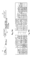
- the system controller 15 has signal levels 1 to 7 of a 3-line parallel signal as communication commands.
- the communication cable 20 converts these signal levels 1 to 7 to signal levels 1 to 7 of a 4-line parallel signal as corresponding communication commands for the HDD recorder 16.
- the communication commands for the HDD recorder 16 may include for example commands for static image capture, moving image capture start, moving image capture stop, and CD-R write.
- the signal levels 1 to 7 of the 3-line parallel signal output from the system controller 15 and the signal levels 1 to 7 of the 4-line parallel signal into which these are converted are for example set as detailed in a command conversion table for the HDD recorder 16 shown in Fig. 5B.
- the 3-line parallel signal pins 1 to 3 continue in a no-signal state.
- the 3-line parallel signal pins 1 to 3 assume one of the above-mentioned signal level 1 to 7 states, and return to the no-signal state after 500ms elapses.
- the communication cable 20 When it is not receiving a 3-line parallel signal level 1 to 7, the communication cable 20 keeps the 4-line parallel signal pins 1 to 4 for the HDD recorder in a no-operation state.
- the communication cable 20 When it receives a 3-line parallel signal level 1 to 7 from the system controller 15, the communication cable 20 outputs a corresponding converted communication command such as static image capture, moving image capture start, moving image capture stop, or CD-R write, as shown in Fig. 5B, to the 4-line parallel signal pins 1 to 4 for the HDD recorder, for 100ms, and after 100ms elapses returns them to the no-operation state.
- Figs. 6A and 6B the case of the light 17 being used as a peripheral appliance 19 will be discussed.
- the system controller 15 and the light 17 are connected by a communication cable 20.
- the controller-side connector 21 uses for communication the terminals of 3 pins among the 7 pins, and the peripheral appliance side connector 24 uses for communication the terminals of 3 pins among the 7 pins.
- the controller-side connector 21 also uses the terminal of 1 pin among the 7 pins for power supply.
- the system controller 15 has signal levels 1 to 7 of a 3-line parallel signal as communication commands.
- the communication cable 20 converts these signal levels 1 to 7 to corresponding 3-line serial signal levels 1 to 7 and outputs them as communication commands for the light 17.
- the communication commands for the light 17 are for example commands such as light on, light off, and brightness 50% to 100%.
- the signal levels 1 to 7 of the 3-line parallel signal output from the system controller 15 and the signal levels 1 to 7 of the 3-line serial signal to which these signal levels 1 to 7 are converted are for example set as detailed in the command conversion table for the light 17 shown in Fig. 6B.
- the 3-line parallel signal pins 1 to 3 continue in a no-signal state.
- the 3-line parallel signal pins 1 to 3 assume one of the above-mentioned signal level 1 to 7 states, and return to the no-signal state after 500ms elapses.
- the communication cable 20 When it is not receiving a 3-line parallel signal level 1 to 7, the communication cable 20 does not perform serial command transmission for the light 17, and continues a no-operation state.
- the communication cable 20 When it receives a 3-line parallel signal level 1 to 7 from the system controller 15, the communication cable 20 outputs a corresponding converted communication command such as light on, light off, brightness 50% to 100%, as shown in Fig. 6B, to the 3-line serial signal pins 1 to 3 for the light, for 100ms, and after 100ms elapses returns them to the no-operation state.
- the communication cable 20 constructed like this operates for example in accordance with the flow charts shown in Fig. 7 through Fig. 9.
- a user connects the system controller 15 and the respective peripheral appliance 19 with a communication cable 20.
- the cases of an HDD recorder 16 and a light 17 being used as peripheral appliances 19, as discussed above, will be described.
- step S1 an operator turns on the power supply of the system controller 15 (step S1).
- the communication cable 20 is supplied with power from the system controller 15 through 1 pin of the controller-side connector 21.
- the control part 33 of the communication cable 20 reads out a communication command conversion mode from the settings storing part 36 (step S2).
- the control part 33 determines what the communication command conversion mode read out is (step S3).
- control part 33 When the communication command conversion mode read out is an HDD Recorder mode, the control part 33 indicates the HDD recorder 16 on the display part 31 (step S4), and sets the input/output selecting circuit 34 to the HDD recorder 16 (step S5). The control part 33 then shifts to a Normal mode (step S8).
- the control part 33 indicates the light 17 on the display part 31 (step S6), and sets the input/output selecting circuit 34 to the light 17 (step S7). The control part 33 then shifts to the Normal mode (step S8).
- control part 33 determines whether or not the setting button 32 has been steadily pushed by a user for a predetermined time (step S11).
- step S10 When the setting button 32 has been steadily pushed, the control part 33 shifts to a Setting mode (step S10), which will be further discussed later.
- step S10 When on the other hand the setting button 32 has not been pressed steadily, the control part 33 continues in the Normal mode.
- the control part 33 determines whether or not any one of the signal levels 1 to 7 of the 3-line parallel signal output from the system controller 15 has been received (step S12).
- step S13 determines what the present communication command conversion mode is set to (step S13).
- the control part 33 converts the signal from the system controller 15 into a communication command in accordance with the communication command conversion table for the HDD recorder stored in the settings storing part 36 (step S14).
- the control part 33 then outputs the signal obtained by communication command conversion as a 4-line parallel signal (step S15).
- the 3-line parallel signal output from the system controller 15 is at signal level 2, or LH (0V, 0V, 5V), it is converted to LLLH (0V, 0V, 0V, 5V), which is the static image capture operation command.
- LLLH (0V, 0V, 0V, 5V)
- the converted signal is output to the HDD recorder 16 through the peripheral appliance side connector 24.
- the HDD recorder 16 receiving this signal performs a static image capture operation and records static image data.
- the control part 33 converts the signal from the system controller 15 into the communication command in accordance with the command conversion table for the light stored in the settings storing part 36 (step S16).
- the control part 33 then outputs the signal obtained by communication command conversion as a 3-line serial signal (step S17).
- the converted signal is output to the light 17 through the peripheral appliance side connector 24.
- the light 17 receiving the signal turns on and illuminates the operating theater.
- the communication cable 20 can execute communication command conversion processing on a signal output from the system controller 15 and output it to the HDD recorder 16 or the light 17, and these peripheral appliances 19 having different forms of communication can be controlled.
- the control part 33 determines whether or not a communication command conversion mode to be set has been selected by a user pushing the setting button 32 briefly (step S21). Where it is determined that the setting button 32 is not pushed briefly, the method proceeds to step S30 and shifts to Normal mode.
- control part 33 determines what the current communication command conversion mode is (step S22).
- the control part 33 changes the communication command conversion mode to the light 17 (step S23).
- the control part 33 changes the display on the display part 31 to indicate the light 17 (step S24) and changes the input/output selecting circuit 34 over to serve the light 17 (step S25).
- the control part 33 changes the communication command conversion mode to the HDD recorder 16 (step S26).
- the control part 33 changes the display on the display part 31 to indicate the HDD recorder 16 (step S27) and changes the input/output selecting circuit 34 over to serve the HDD recorder 16 (step S28).
- the control part 33 stores data of the changed communication command conversion mode in the settings storing part 36 (step S29) and shifts to Normal mode at step S30.
- the communication cable 20 can change the set communication command conversion mode in correspondence with the peripheral appliance 19, and data of the changed setting can be stored in the settings storing part 36.
- an HDD recorder 16 and a light 17 were used as examples of peripheral appliances 19 having different forms of communication.
- other peripheral appliances 19 are possible, such as an electrocardiogram, an anesthesia system having an anesthesia unit, and/or equipment such as a bed may be connected to the system controller 15 and centrally controlled.
- the invention is not limited to this, and as long as there is provided a control part that performs communication command conversion processing as a converting part, the input part or the output part may alternatively be constructed so that communication can be carried out for example wirelessly in which the communication device can comprise at least one transmitter and receiver for at least partial wireless communication between the peripheral appliances 19 and the system controller 15.
- the communication cable 20 of this embodiment can be connected to a system controller 15 (central control unit) and central control carried out even if forms of communication differ.
- the invention was applied to an endoscope surgery system, the invention is not limited to this and can of course be applied to industrial and other systems for centrally controlling object devices.
- the communication device of this invention by making possible communication between a central control unit and peripheral appliances even when their forms of communication differ and thereby making central control of the peripheral appliances possible, is useful wherever object appliances are to be centrally controlled in the medical treatment field, industrial fields and other fields.
Landscapes
- Life Sciences & Earth Sciences (AREA)
- Health & Medical Sciences (AREA)
- Surgery (AREA)
- Engineering & Computer Science (AREA)
- Biophysics (AREA)
- Medical Informatics (AREA)
- Nuclear Medicine, Radiotherapy & Molecular Imaging (AREA)
- Optics & Photonics (AREA)
- Pathology (AREA)
- Radiology & Medical Imaging (AREA)
- Veterinary Medicine (AREA)
- Biomedical Technology (AREA)
- Heart & Thoracic Surgery (AREA)
- Physics & Mathematics (AREA)
- Molecular Biology (AREA)
- Animal Behavior & Ethology (AREA)
- General Health & Medical Sciences (AREA)
- Public Health (AREA)
- Signal Processing (AREA)
- Selective Calling Equipment (AREA)
- Communication Control (AREA)
Applications Claiming Priority (2)
| Application Number | Priority Date | Filing Date | Title |
|---|---|---|---|
| JP2004114720 | 2004-04-08 | ||
| JP2004114720A JP2005303549A (ja) | 2004-04-08 | 2004-04-08 | 通信装置 |
Publications (2)
| Publication Number | Publication Date |
|---|---|
| EP1587043A2 true EP1587043A2 (fr) | 2005-10-19 |
| EP1587043A3 EP1587043A3 (fr) | 2007-12-19 |
Family
ID=34934562
Family Applications (1)
| Application Number | Title | Priority Date | Filing Date |
|---|---|---|---|
| EP05006810A Withdrawn EP1587043A3 (fr) | 2004-04-08 | 2005-03-29 | Dispositif de communication et câble de communication |
Country Status (3)
| Country | Link |
|---|---|
| US (1) | US20050236907A1 (fr) |
| EP (1) | EP1587043A3 (fr) |
| JP (1) | JP2005303549A (fr) |
Families Citing this family (2)
| Publication number | Priority date | Publication date | Assignee | Title |
|---|---|---|---|---|
| JP6057549B2 (ja) * | 2012-06-04 | 2017-01-11 | オリンパス株式会社 | 制御信号変換装置、コントローラ、被制御機器、機器制御システム、及び状態検出方法 |
| DE102024103538B3 (de) * | 2024-02-08 | 2025-05-22 | Schölly Fiberoptic GmbH | Medizinisches Visualisierungssystem, medizinisches Operationssystem sowie Verfahren zum Visualisieren eines Videobilddatenstroms |
Family Cites Families (9)
| Publication number | Priority date | Publication date | Assignee | Title |
|---|---|---|---|---|
| US3749845A (en) * | 1971-08-27 | 1973-07-31 | Bell Telephone Labor Inc | Digital data communication system |
| US5003591A (en) * | 1989-05-25 | 1991-03-26 | General Instrument Corporation | Functionally modifiable cable television converter system |
| US5251909A (en) * | 1991-05-28 | 1993-10-12 | Reed Michael J | Secured high throughput data channel for public broadcast system |
| US5802467A (en) * | 1995-09-28 | 1998-09-01 | Innovative Intelcom Industries | Wireless and wired communications, command, control and sensing system for sound and/or data transmission and reception |
| US5704364A (en) * | 1995-11-08 | 1998-01-06 | Instromedix, Inc. | Concurrent medical patient data and voice communication method and apparatus |
| US6398727B1 (en) * | 1998-12-23 | 2002-06-04 | Baxter International Inc. | Method and apparatus for providing patient care |
| US7149474B1 (en) * | 1999-11-02 | 2006-12-12 | Broadcom Corporation | Wireless cable replacement system |
| US6491649B1 (en) * | 2000-10-06 | 2002-12-10 | Mark P. Ombrellaro | Device for the direct manual examination of a patient in a non-contiguous location |
| US20030174068A1 (en) * | 2002-03-15 | 2003-09-18 | Dobos Jeffrey A. | Apparatus for calibrating a digital field sensor |
-
2004
- 2004-04-08 JP JP2004114720A patent/JP2005303549A/ja not_active Withdrawn
-
2005
- 2005-03-22 US US11/086,153 patent/US20050236907A1/en not_active Abandoned
- 2005-03-29 EP EP05006810A patent/EP1587043A3/fr not_active Withdrawn
Also Published As
| Publication number | Publication date |
|---|---|
| EP1587043A3 (fr) | 2007-12-19 |
| US20050236907A1 (en) | 2005-10-27 |
| JP2005303549A (ja) | 2005-10-27 |
Similar Documents
| Publication | Publication Date | Title |
|---|---|---|
| CN110799085B (zh) | 无线内窥镜和无线内窥镜系统 | |
| CN109475269B (zh) | 无线内窥镜装置 | |
| JP5498006B2 (ja) | 医療制御装置及び該システム | |
| JP5340609B2 (ja) | 内視鏡装置 | |
| JP3706326B2 (ja) | 内視鏡装置 | |
| EP1806108A1 (fr) | Systeme de fonctionnement ultrasonique | |
| US20080019393A1 (en) | Operation system control apparatus, operation system control method and operation system | |
| US20050149001A1 (en) | Operation support system and support method of operation support system | |
| WO2016072147A1 (fr) | Dispositif d'observation et procédé d'observation | |
| JP2001353124A (ja) | 内視鏡装置 | |
| JP5155037B2 (ja) | 受像機及び画像送信機からなる無線通信システム及び、その無線通信方法 | |
| WO2019198364A1 (fr) | Dispositif endoscope | |
| US7896801B2 (en) | Endoscope with rigidity variation section | |
| CN118749867A (zh) | 内窥镜可视化系统 | |
| JP5816524B2 (ja) | ワイヤレス内視鏡システム | |
| CN112822969B (zh) | 用于一次性输尿管镜的按钮适配器 | |
| JP6300708B2 (ja) | 内視鏡装置及び内視鏡装置の画像伝送方法 | |
| WO2007034891A1 (fr) | Récepteur | |
| EP1587043A2 (fr) | Dispositif de communication et câble de communication | |
| WO2007029815A1 (fr) | Visualiseur d’image intra-lumen | |
| JP4477286B2 (ja) | 電子内視鏡システム | |
| JP2009039249A (ja) | 内視鏡システム | |
| WO2020202490A1 (fr) | Dispositif endoscope sans fil | |
| JP2003070805A (ja) | 医療機器制御装置 | |
| JP2004280605A (ja) | 制御システム |
Legal Events
| Date | Code | Title | Description |
|---|---|---|---|
| PUAI | Public reference made under article 153(3) epc to a published international application that has entered the european phase |
Free format text: ORIGINAL CODE: 0009012 |
|
| AK | Designated contracting states |
Kind code of ref document: A2 Designated state(s): AT BE BG CH CY CZ DE DK EE ES FI FR GB GR HU IE IS IT LI LT LU MC NL PL PT RO SE SI SK TR |
|
| AX | Request for extension of the european patent |
Extension state: AL BA HR LV MK YU |
|
| PUAL | Search report despatched |
Free format text: ORIGINAL CODE: 0009013 |
|
| AK | Designated contracting states |
Kind code of ref document: A3 Designated state(s): AT BE BG CH CY CZ DE DK EE ES FI FR GB GR HU IE IS IT LI LT LU MC NL PL PT RO SE SI SK TR |
|
| AX | Request for extension of the european patent |
Extension state: AL BA HR LV MK YU |
|
| AKX | Designation fees paid | ||
| STAA | Information on the status of an ep patent application or granted ep patent |
Free format text: STATUS: THE APPLICATION IS DEEMED TO BE WITHDRAWN |
|
| 18D | Application deemed to be withdrawn |
Effective date: 20080620 |
|
| REG | Reference to a national code |
Ref country code: DE Ref legal event code: 8566 |