EP1587176A1 - Anschlussvorrichtung zum abgedichteten Anschluss von Leitern eines Kabels an eine Elektronikbaugruppe in einem Gehäuse - Google Patents
Anschlussvorrichtung zum abgedichteten Anschluss von Leitern eines Kabels an eine Elektronikbaugruppe in einem Gehäuse Download PDFInfo
- Publication number
- EP1587176A1 EP1587176A1 EP05005936A EP05005936A EP1587176A1 EP 1587176 A1 EP1587176 A1 EP 1587176A1 EP 05005936 A EP05005936 A EP 05005936A EP 05005936 A EP05005936 A EP 05005936A EP 1587176 A1 EP1587176 A1 EP 1587176A1
- Authority
- EP
- European Patent Office
- Prior art keywords
- housing
- connecting device
- cable
- sealing ring
- outer housing
- Prior art date
- Legal status (The legal status is an assumption and is not a legal conclusion. Google has not performed a legal analysis and makes no representation as to the accuracy of the status listed.)
- Granted
Links
- 239000004020 conductor Substances 0.000 title claims abstract description 18
- 238000007789 sealing Methods 0.000 claims abstract description 24
- 230000007704 transition Effects 0.000 claims description 4
- 230000013011 mating Effects 0.000 claims description 2
- 238000000465 moulding Methods 0.000 claims description 2
- 238000002347 injection Methods 0.000 claims 1
- 239000007924 injection Substances 0.000 claims 1
- 239000000463 material Substances 0.000 claims 1
- ZAKOWWREFLAJOT-CEFNRUSXSA-N D-alpha-tocopherylacetate Chemical compound CC(=O)OC1=C(C)C(C)=C2O[C@@](CCC[C@H](C)CCC[C@H](C)CCCC(C)C)(C)CCC2=C1C ZAKOWWREFLAJOT-CEFNRUSXSA-N 0.000 description 1
- 238000005516 engineering process Methods 0.000 description 1
- 238000001746 injection moulding Methods 0.000 description 1
- 238000000034 method Methods 0.000 description 1
- 239000003566 sealing material Substances 0.000 description 1
- 239000000243 solution Substances 0.000 description 1
Images
Classifications
-
- H—ELECTRICITY
- H01—ELECTRIC ELEMENTS
- H01R—ELECTRICALLY-CONDUCTIVE CONNECTIONS; STRUCTURAL ASSOCIATIONS OF A PLURALITY OF MUTUALLY-INSULATED ELECTRICAL CONNECTING ELEMENTS; COUPLING DEVICES; CURRENT COLLECTORS
- H01R13/00—Details of coupling devices of the kinds covered by groups H01R12/70 or H01R24/00 - H01R33/00
- H01R13/46—Bases; Cases
- H01R13/52—Dustproof, splashproof, drip-proof, waterproof, or flameproof cases
- H01R13/5202—Sealing means between parts of housing or between housing part and a wall, e.g. sealing rings
-
- H—ELECTRICITY
- H01—ELECTRIC ELEMENTS
- H01R—ELECTRICALLY-CONDUCTIVE CONNECTIONS; STRUCTURAL ASSOCIATIONS OF A PLURALITY OF MUTUALLY-INSULATED ELECTRICAL CONNECTING ELEMENTS; COUPLING DEVICES; CURRENT COLLECTORS
- H01R13/00—Details of coupling devices of the kinds covered by groups H01R12/70 or H01R24/00 - H01R33/00
- H01R13/46—Bases; Cases
- H01R13/52—Dustproof, splashproof, drip-proof, waterproof, or flameproof cases
- H01R13/5205—Sealing means between cable and housing, e.g. grommet
Definitions
- the invention relates to a connection device for the sealed connection of conductors a cable, in particular to an electronic assembly in a housing, which is provided with at least one or more apertures, wherein the conductors the cable are connected to a male or a female part, which is to mate with a corresponding socket or plug part on the electronic module is designed and wherein the male or female part to which the Head of the cable are connected, at least in sections from the breakthrough of the housing protrudes outward.
- connection devices are known per se in a variety of embodiments and have proven themselves. Under harsh conditions, it is desirable to have one Connecting device also provide in sealed design. The solution of this Problems is the object of the invention.
- connection device with an advantageously designed and cost-effective housing, with which it is easily possible, to realize a sealed connection to the electronics assembly in the housing and still the u.U. unsealed trained male and female parts to use any standard.
- specially sealed male and female parts with sealed bushing by a wall in particular a housing can be dispensed with. It Rather, any plug and socket connection system is simple also designed for sealed passage through a wall of a housing become.
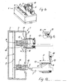
- Fig. 1a and b show a housing 1 with a base 2 and a lid 3, the Receiving an electronic assembly 4, here a populated circuit board 5, designed is.
- a wall 8 of the housing 1 provided with a plurality of openings 9, through each of which a plug part 10 can be pushed through, the corresponding Socket parts 11 on the circuit board 5 can be plugged.
- the plug part 10 is made of the Housing 1 from the openings 9 outwards.
- the plug and socket parts 10, 11 are standard components - e.g. Plug and socket parts of the standard "ECON" - which also in non-sealed Design can be designed.
- the position of the male and female parts 10, 11 also be reversed, so that the plug part fixed to the electronic assembly 4 and the Socket part with the conductors 6 of the cable 7 would be connected (not shown).
- the ladder 6 are connected to the plug part 10 in any connection technique, e.g. using IDC technology (not shown here).
- the plug part 10 and the socket part 11 formed as a largely rectangular, flat components, wherein the conductor. 6 (four examples here) lie in a plane parallel to each other.
- the outer housing 12 has sealing rings 13, 14 and is by means of latching arms 15, 16, the are designed to intervene in the respective opening 9 of the housing 1 and to be locked there, to attach to the housing 1. It points to the geometry of the housing 1 protruding portion of the male part 10 adapted geometry on, so that it can be pushed in the direction of the housing 1 via the plug part 10, if this is locked on the socket part 11.
- the housing 12 At its breakthrough 9 side facing the housing 12 is designed to be open and provided with the first sealing ring 13, which in a simple way the transition region between the opening 9 and the housing facing the open side of the Outer casing 12 seals, wherein the openings 9 with a circumferential step-like Flange extension 17 are provided, on which the likewise stepped formed first sealing ring 13 rests.
- the outer housing 12 with a folding Cover 18 provided here on at least one, here two film hinge (s) 19 is connected to the rest of the housing 12.
- the second sealing ring 14 serves To seal the housing 12 in the region of its cover 18.
- the lid 18 is provided with locking projections 20, with which the lid 18 at undercuts 21 of the housing 12 can be latched.
- a recess 22 in the lid 18th serves to pass the cable 7 to the plug part 10, which is the outer housing 12th overlaps.
- a sealing fitting 23 is molded or inserted, which has a geometry which corresponds with the geometry of the Cable 7 or its conductor corresponds and even has a recess 24, which is adapted to the geometry of the cable or its conductors.
- a corresponding recess 25 is provided in the inner periphery of the second sealing ring 24, so that the sealing ring 13 and the gasket 4, the cable or its Advantageously, the conductor should comprise positive-locking sealing.
- these recesses 24, 25 can also be connected to the geometry of a flat cable or several side by side be adapted in the manner of a flat cable (see the upper housing over 12 in Fig. 1b).
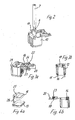
- the first sealing ring 13 and the second sealing ring 14 - which are spaced parallel to each other are arranged in the housing 12, are by a web 26 of sealing material directly connected and are thus provided as a one-piece, easily assembled component (FIG. 4) or preferably each sharpened, in particular in the 2-component injection molding process.
- the cable 7 is first stripped in the end and the head. 6 are then connected to the plug part 10. Then, the outer housing 12 with open lid part pulled over the plug part 10. Then the mating of plug part 10 and socket part 11. Then, the outer housing 12 to the housing pushed (arrow P in Fig. 2), then latched to the housing 1 and the lid 18 is closed, so that both the cable 7 sealed encompassed form fit and the Transition to the housing 1 is sealed in an advantageous and simple manner.
Landscapes
- Connector Housings Or Holding Contact Members (AREA)
- Connections By Means Of Piercing Elements, Nuts, Or Screws (AREA)
- Multi-Conductor Connections (AREA)
- Connections Arranged To Contact A Plurality Of Conductors (AREA)
- Cable Accessories (AREA)
Abstract
Description
- Fig. 1a
- eine perspektivische Ansicht eines Gehäuses mit Anschlussvorrichtung;
- Fig. 1b
- einen Schnitt durch die Anordnung aus Fig. 1a;
- Fig. 1c
- eine Ausschnittsvergrößerung aus Fig. 1 b;
- Fig. 2
- eine perspektivische Darstellung eines Übergehäuses mit Steckerteil und Kabel;
- Fig. 3a
- eine perspektivische Darstellung des Übergehäuses aus Fig. 2;
- Fig. 3b
- einen Schnitt durch das Übergehäuse der Fig. 3a;
- Fig. 4a
- eine perspektivische Darstellung der Dichtung des Übergehäuses aus Fig. 3a; und
- Fig. 4b
- einen Schnitt durch die Dichtung aus Fig. 4a mit Übergehäuse bei offenem Deckel (Rastarme nicht dargestellt).
- Gehäuse
- 1
- Grundteil
- 2
- Deckel
- 3
- Elektronikbaugruppe
- 4
- Leiterplatte
- 5
- Leiter
- 6
- Kabel
- 7
- Wandung
- 8
- Durchbrüche
- 9
- Steckerteil
- 10
- Buchsenteile
- 11
- Übergehäuse
- 12
- Dichtringe
- 13, 14
- Rastarme
- 15, 16
- Flanschansatz
- 17
- Deckel
- 18
- Filmscharnier
- 19
- Rastvorsprüngen
- 20
- Hinterschnitte
- 21
- Aussparung
- 22
- Dichtungsformstück
- 23
- Aussparung
- 24
- Aussparung
- 25
- Steg
- 26
Claims (12)
- Anschlußvorrichtung zum abgedichteten Anschluss von Leitern (7) eines Kabels (6), insbesondere an eine Elektronikbaugruppe (4) in einem Gehäuse (1), welches mit wenigstens einem oder mehreren Durchbrüchen (9) versehen ist,a. wobei die Leiter (7) des Kabels (6) jeweils an ein Stecker- oder ein Buchsenteil (10) angeschlossen sind, das zum Zusammenstecken mit einem korrespondierenden Buchsen- oder Steckerteil (11) an der Elektronikbaugruppe (4) ausgelegt ist, undb. wobei das Stecker- oder Buchsenteil (10), an welches die Leiter (7) des Kabels (6) angeschlossen sind, zumindest abschnittsweise aus dem Durchbruch (9) des Gehäuses nach außen vorsteht,
gekennzeichnet durchc. wenigstens ein an dem jeweiligen Durchbruch (9) des Gehäuses verrastbares Übergehäuse (12), welches über den aus dem Gehäuse (1) vorstehenden Abschnitt des Stecker- oder Buchsenteil (10) geschoben ist,d. und einen ersten und einen zweiten Dichtring (13, 14) aufweist, von denen der eine den Übergangsbereich zwischen dem Übergehäuse (12) und dem Durchbruch (9) abdichtet und der andere den Bereich der Durchführung des Kabels (7) oder seiner Leiter (6) in das Übergehäuse abdichtet. - Anschlußvorrichtung nach Anspruch 1, dadurch gekennzeichnet, dass der erste und der zweite Dichtring (13, 14) über einen Materialsteg (26) direkt miteinander verbunden sind.
- Anschlußvorrichtung nach Anspruch 1, dadurch gekennzeichnet, dass der erste und der zweite Dichtring (13, 14) angepritzt ausgelegt sind.
- Anschlußvorrichtung nach Anspruch 1 oder 2, dadurch gekennzeichnet, dass die zusammensteckbaren Stecker- und Buchsenteile (10, 11) nicht in abgedichteter Bauart ausgebildet sind.
- Anschlußvorrichtung nach einem der vorstehenden Ansprüche, dadurch gekennzeichnet, dass das Steckerteil (10) und das Buchsenteil (11) als weitgehend rechtwinklige, flache Bauteile ausgebildet sind, wobei die Leiter (6) am Steckerteil (11) in einer Ebene parallel nebeneinander angeordnet sind.
- Anschlußvorrichtung nach einem der vorstehenden Ansprüche, dadurch gekennzeichnet, dass das Übergehäuse (12) Rastarme (15, 16) aufweist, die dazu ausgelegt sind, jeweils in einen der Durchbrüche (9) des Gehäuses (1) einzugreifen und dort verrastet zu werden.
- Anschlußvorrichtung nach einem der vorstehenden Ansprüche, dadurch gekennzeichnet, dass die Durchbrüche (9) mit einem umlaufenden stufenartigen Flanschansatz (17) versehen sind, auf welchem der ebenfalls gestuft ausgebildete erste Dichtring (13) aufliegt.
- Anschlußvorrichtung nach einem der vorstehenden Ansprüche, dadurch gekennzeichnet, dass das Übergehäuse (12) an seiner vom Gehäuse (1) abgewandten Seite mit einem klappbaren Deckel (18) versehen ist.
- Anschlußvorrichtung nach einem der vorstehenden Ansprüche, dadurch gekennzeichnet, dass der Deckel (18) über wenigstens ein Filmscharnier (19) mit dem übrigen Übergehäuse (12) verbunden ist.
- Anschlußvorrichtung nach einem der vorstehenden Ansprüche, dadurch gekennzeichnet, dass der Deckel (18) mit Rastvorsprüngen (20) versehen ist, mit denen der Deckel (18) an Hinterschnitten (21) des Übergehäuses (12) verrastbar ist.
- Anschlußvorrichtung nach einem der vorstehenden Ansprüche, dadurch gekennzeichnet, dass eine Aussparung (22) im Deckel (18) ausgebildet ist, die zur Durchführung des Kabels (7) oder seiner Leiter (6) zum Steckerteil (10) ausgelegt ist, welches vom Übergehäuse (12) übergriffen ist.
- Anschlußvorrichtung nach einem der vorstehenden Ansprüche, dadurch gekennzeichnet, dass in die Aussparung (22) im Deckel (18) ein Dichtungsformstück (23) eingesetzt oder angespitzt ist, welches eine Aussparung (24) aufweist, welche an die Geometrie des Kabels (7) und/oder seiner Leiter (6) angepasst ist, wobei eine entsprechende Aussparung (25) am Innenumfang des zweiten Dichtrings (24) vorgesehen ist, so dass der Dichtring (13) und das Dichtungsformstück (23) das Kabel (7) und/oder dessen Leiter (6) formschlüssig dichtend umfassen.
Applications Claiming Priority (2)
| Application Number | Priority Date | Filing Date | Title |
|---|---|---|---|
| DE202004005878U DE202004005878U1 (de) | 2004-04-14 | 2004-04-14 | Anschlußvorrichtung zum abgedichteten Anschluß von Leitern eines Kabels an eine Elektronikbaugruppe in einem Gehäuse |
| DE202004005878U | 2004-04-14 |
Publications (2)
| Publication Number | Publication Date |
|---|---|
| EP1587176A1 true EP1587176A1 (de) | 2005-10-19 |
| EP1587176B1 EP1587176B1 (de) | 2007-02-28 |
Family
ID=34934345
Family Applications (1)
| Application Number | Title | Priority Date | Filing Date |
|---|---|---|---|
| EP05005936A Expired - Lifetime EP1587176B1 (de) | 2004-04-14 | 2005-03-18 | Anschlussvorrichtung zum abgedichteten Anschluss von Leitern eines Kabels an eine Elektronikbaugruppe in einem Gehäuse |
Country Status (4)
| Country | Link |
|---|---|
| EP (1) | EP1587176B1 (de) |
| AT (1) | ATE355636T1 (de) |
| DE (2) | DE202004005878U1 (de) |
| ES (1) | ES2282942T3 (de) |
Cited By (1)
| Publication number | Priority date | Publication date | Assignee | Title |
|---|---|---|---|---|
| WO2016162102A1 (de) * | 2015-04-07 | 2016-10-13 | Rosenberger Hochfrequenztechnik Gmbh & Co. Kg | Verfahren zum herstellen eines wasserdichten steckverbinders und steckverbinder |
Families Citing this family (4)
| Publication number | Priority date | Publication date | Assignee | Title |
|---|---|---|---|---|
| WO2007090382A2 (de) | 2006-02-10 | 2007-08-16 | Marquardt Gmbh | Elektrischer schnappschalter mit abdichtung am anschluss |
| DE202009000899U1 (de) * | 2009-01-23 | 2010-06-17 | Weidmüller Interface GmbH & Co. KG | Fixiervorrichtung zum Fixieren eines Kabels an einer Gehäusedurchführung |
| US9769551B2 (en) | 2014-12-31 | 2017-09-19 | Skullcandy, Inc. | Method of connecting cable to headphone, and headphone formed using such methods |
| DE112018008135B4 (de) | 2018-12-14 | 2024-07-25 | Mitsubishi Electric Corporation | Elektromotor |
Citations (3)
| Publication number | Priority date | Publication date | Assignee | Title |
|---|---|---|---|---|
| DE8904419U1 (de) * | 1989-04-08 | 1989-06-29 | Rittal-Werk Rudolf Loh GmbH & Co. KG, 35745 Herborn | Vorrichtung zum Abdecken einer bestückten Leiterplatte |
| DE19640891A1 (de) * | 1996-10-04 | 1998-04-09 | Alsthom Cge Alcatel | Gehäuse mit einer an einer Gehäusewand befestigten Kontaktbuchse |
| JP2001148265A (ja) * | 1999-11-22 | 2001-05-29 | Sumitomo Wiring Syst Ltd | フラットケーブル用コネクタ |
Family Cites Families (7)
| Publication number | Priority date | Publication date | Assignee | Title |
|---|---|---|---|---|
| DE3036267C2 (de) * | 1980-09-26 | 1984-11-29 | Kabelwerke Reinshagen Gmbh, 5600 Wuppertal | Wasserdichter elektrischer Steckverbinder und Verfahren zu seiner Herstellung |
| DE3544785A1 (de) * | 1985-12-18 | 1987-06-19 | Bayerische Motoren Werke Ag | Abdichtungssystem fuer leitungen |
| US5328388A (en) * | 1993-05-28 | 1994-07-12 | Yazaki Corporation | Modular electrical connector |
| US5626489A (en) * | 1995-04-13 | 1997-05-06 | Molex Incorporated | Sealed electrical connector assembly |
| DE29521213U1 (de) * | 1995-04-21 | 1997-01-09 | Contact GmbH Elektrische Bauelemente, 70565 Stuttgart | Steckverbindersystem |
| US6162082A (en) * | 1999-01-28 | 2000-12-19 | Badger Meter, Inc. | Submersible electrical connector and method for quick connection and disconnection including tamper indication |
| DE20121322U1 (de) * | 2001-07-23 | 2002-07-18 | Dätwyler AG Schweizerische Kabel-, Gummi- und Kunststoffwerke, Altdorf, Uri | Anschlußsystem, Anschlußdose und Anschlußkabel |
-
2004
- 2004-04-14 DE DE202004005878U patent/DE202004005878U1/de not_active Expired - Lifetime
-
2005
- 2005-03-18 DE DE502005000407T patent/DE502005000407D1/de not_active Expired - Lifetime
- 2005-03-18 AT AT05005936T patent/ATE355636T1/de active
- 2005-03-18 ES ES05005936T patent/ES2282942T3/es not_active Expired - Lifetime
- 2005-03-18 EP EP05005936A patent/EP1587176B1/de not_active Expired - Lifetime
Patent Citations (3)
| Publication number | Priority date | Publication date | Assignee | Title |
|---|---|---|---|---|
| DE8904419U1 (de) * | 1989-04-08 | 1989-06-29 | Rittal-Werk Rudolf Loh GmbH & Co. KG, 35745 Herborn | Vorrichtung zum Abdecken einer bestückten Leiterplatte |
| DE19640891A1 (de) * | 1996-10-04 | 1998-04-09 | Alsthom Cge Alcatel | Gehäuse mit einer an einer Gehäusewand befestigten Kontaktbuchse |
| JP2001148265A (ja) * | 1999-11-22 | 2001-05-29 | Sumitomo Wiring Syst Ltd | フラットケーブル用コネクタ |
Non-Patent Citations (1)
| Title |
|---|
| PATENT ABSTRACTS OF JAPAN vol. 2000, no. 2209 9 March 2001 (2001-03-09) * |
Cited By (5)
| Publication number | Priority date | Publication date | Assignee | Title |
|---|---|---|---|---|
| WO2016162102A1 (de) * | 2015-04-07 | 2016-10-13 | Rosenberger Hochfrequenztechnik Gmbh & Co. Kg | Verfahren zum herstellen eines wasserdichten steckverbinders und steckverbinder |
| CN107534241A (zh) * | 2015-04-07 | 2018-01-02 | 罗森伯格高频技术有限及两合公司 | 用于生产防水型插接连接器的方法和插接连接器 |
| JP2018511154A (ja) * | 2015-04-07 | 2018-04-19 | ローゼンベルガー ホーフフレクベンツテクニーク ゲーエムベーハー ウント ツェーオー カーゲー | 水密プラグコネクタの製造のための方法およびプラグコネクタ |
| US10020628B2 (en) | 2015-04-07 | 2018-07-10 | Rosenberger Hochfrequenztechnik Gmbh & Co. Kg | Method for producing a water-tight plug connector |
| CN107534241B (zh) * | 2015-04-07 | 2019-05-28 | 罗森伯格高频技术有限及两合公司 | 用于生产防水型插接连接器的方法和插接连接器 |
Also Published As
| Publication number | Publication date |
|---|---|
| DE202004005878U1 (de) | 2005-09-08 |
| DE502005000407D1 (de) | 2007-04-12 |
| EP1587176B1 (de) | 2007-02-28 |
| ES2282942T3 (es) | 2007-10-16 |
| ATE355636T1 (de) | 2006-03-15 |
Similar Documents
| Publication | Publication Date | Title |
|---|---|---|
| DE10244408B4 (de) | Durchgangstülle mit Kunststoffeinsatz | |
| DE69429493T2 (de) | Verbinder und dessen Herstellungsverfahren | |
| DE112019003595T5 (de) | Elektrischer Steckverbinder, der unterschiedliche Dichtungsanordnungen akzeptiert | |
| DE19641408C2 (de) | Wasserdichter elektrischer Steckverbinder | |
| DE10041837A1 (de) | Wasserdichter Stecker | |
| DE102015214238A1 (de) | Wasserdichter Steckverbinder | |
| DE112008001928T5 (de) | Steckverbinder | |
| DE60210215T2 (de) | Wasserdichter Verbinder für flexibles Flachkabel | |
| DE102015114289A1 (de) | Elektrische Kabelbaugruppe | |
| DE102019005171A1 (de) | Elektromotor, insbesondere Außenläufermotor | |
| DE102005021615A1 (de) | Gehäuseglied mit Steckverbindungsteil | |
| DE10115322A1 (de) | Kraftstoff-Einspritzvorrichtung für Brennkraftmaschinen, insbesondere Common-Rail-Injektor | |
| EP3631906B1 (de) | Elektrische steckverbindung mit entwässerungsvorrichtung | |
| EP1587176B1 (de) | Anschlussvorrichtung zum abgedichteten Anschluss von Leitern eines Kabels an eine Elektronikbaugruppe in einem Gehäuse | |
| DE102016211372A1 (de) | Kabelbaumstecker | |
| DE60309803T2 (de) | Fixierungsanordnung für Dichtungsteil | |
| DE20318583U1 (de) | Ladesteckverbindersatz mit Adapter | |
| DE102012212430A1 (de) | Verbindungseinrichtung für Leistungshalbleitereinrichtung mit dichtem Steckverbinder | |
| EP3281256B1 (de) | Verfahren zum herstellen eines wasserdichten steckverbinders und steckverbinder | |
| DE19627635C1 (de) | Zündpillen-Steckverbindung | |
| EP3700065A1 (de) | Elektrischer antrieb | |
| EP1760838A1 (de) | Elektrisches Steckverbinderteil | |
| DE102014118685A1 (de) | Hermetisch dichtender Steckverbinder | |
| DE60038709T2 (de) | Wasserdichte Abdichtungsanordnung für Verbinder | |
| DE3720751A1 (de) | Elektrische verbinderanordnung |
Legal Events
| Date | Code | Title | Description |
|---|---|---|---|
| PUAI | Public reference made under article 153(3) epc to a published international application that has entered the european phase |
Free format text: ORIGINAL CODE: 0009012 |
|
| AK | Designated contracting states |
Kind code of ref document: A1 Designated state(s): AT BE BG CH CY CZ DE DK EE ES FI FR GB GR HU IE IS IT LI LT LU MC NL PL PT RO SE SI SK TR |
|
| AX | Request for extension of the european patent |
Extension state: AL BA HR LV MK YU |
|
| 17P | Request for examination filed |
Effective date: 20051123 |
|
| AKX | Designation fees paid |
Designated state(s): AT BE BG CH CY CZ DE DK EE ES FI FR GB GR HU IE IS IT LI LT LU MC NL PL PT RO SE SI SK TR |
|
| GRAP | Despatch of communication of intention to grant a patent |
Free format text: ORIGINAL CODE: EPIDOSNIGR1 |
|
| GRAS | Grant fee paid |
Free format text: ORIGINAL CODE: EPIDOSNIGR3 |
|
| GRAA | (expected) grant |
Free format text: ORIGINAL CODE: 0009210 |
|
| AK | Designated contracting states |
Kind code of ref document: B1 Designated state(s): AT BE BG CH CY CZ DE DK EE ES FI FR GB GR HU IE IS IT LI LT LU MC NL PL PT RO SE SI SK TR |
|
| PG25 | Lapsed in a contracting state [announced via postgrant information from national office to epo] |
Ref country code: PL Free format text: LAPSE BECAUSE OF FAILURE TO SUBMIT A TRANSLATION OF THE DESCRIPTION OR TO PAY THE FEE WITHIN THE PRESCRIBED TIME-LIMIT Effective date: 20070228 Ref country code: SI Free format text: LAPSE BECAUSE OF FAILURE TO SUBMIT A TRANSLATION OF THE DESCRIPTION OR TO PAY THE FEE WITHIN THE PRESCRIBED TIME-LIMIT Effective date: 20070228 Ref country code: NL Free format text: LAPSE BECAUSE OF FAILURE TO SUBMIT A TRANSLATION OF THE DESCRIPTION OR TO PAY THE FEE WITHIN THE PRESCRIBED TIME-LIMIT Effective date: 20070228 Ref country code: DK Free format text: LAPSE BECAUSE OF FAILURE TO SUBMIT A TRANSLATION OF THE DESCRIPTION OR TO PAY THE FEE WITHIN THE PRESCRIBED TIME-LIMIT Effective date: 20070228 Ref country code: FI Free format text: LAPSE BECAUSE OF FAILURE TO SUBMIT A TRANSLATION OF THE DESCRIPTION OR TO PAY THE FEE WITHIN THE PRESCRIBED TIME-LIMIT Effective date: 20070228 |
|
| REG | Reference to a national code |
Ref country code: GB Ref legal event code: FG4D Free format text: NOT ENGLISH |
|
| REG | Reference to a national code |
Ref country code: CH Ref legal event code: EP |
|
| REF | Corresponds to: |
Ref document number: 502005000407 Country of ref document: DE Date of ref document: 20070412 Kind code of ref document: P |
|
| REG | Reference to a national code |
Ref country code: IE Ref legal event code: FG4D Free format text: LANGUAGE OF EP DOCUMENT: GERMAN |
|
| PG25 | Lapsed in a contracting state [announced via postgrant information from national office to epo] |
Ref country code: BG Free format text: LAPSE BECAUSE OF FAILURE TO SUBMIT A TRANSLATION OF THE DESCRIPTION OR TO PAY THE FEE WITHIN THE PRESCRIBED TIME-LIMIT Effective date: 20070528 |
|
| REG | Reference to a national code |
Ref country code: CH Ref legal event code: NV Representative=s name: ISLER & PEDRAZZINI AG |
|
| REG | Reference to a national code |
Ref country code: SE Ref legal event code: TRGR |
|
| GBT | Gb: translation of ep patent filed (gb section 77(6)(a)/1977) |
Effective date: 20070524 |
|
| PG25 | Lapsed in a contracting state [announced via postgrant information from national office to epo] |
Ref country code: IS Free format text: LAPSE BECAUSE OF FAILURE TO SUBMIT A TRANSLATION OF THE DESCRIPTION OR TO PAY THE FEE WITHIN THE PRESCRIBED TIME-LIMIT Effective date: 20070628 |
|
| PG25 | Lapsed in a contracting state [announced via postgrant information from national office to epo] |
Ref country code: PT Free format text: LAPSE BECAUSE OF FAILURE TO SUBMIT A TRANSLATION OF THE DESCRIPTION OR TO PAY THE FEE WITHIN THE PRESCRIBED TIME-LIMIT Effective date: 20070730 |
|
| NLV1 | Nl: lapsed or annulled due to failure to fulfill the requirements of art. 29p and 29m of the patents act | ||
| ET | Fr: translation filed | ||
| REG | Reference to a national code |
Ref country code: CH Ref legal event code: PCAR Free format text: ISLER & PEDRAZZINI AG;POSTFACH 1772;8027 ZUERICH (CH) |
|
| REG | Reference to a national code |
Ref country code: ES Ref legal event code: FG2A Ref document number: 2282942 Country of ref document: ES Kind code of ref document: T3 |
|
| PG25 | Lapsed in a contracting state [announced via postgrant information from national office to epo] |
Ref country code: SK Free format text: LAPSE BECAUSE OF FAILURE TO SUBMIT A TRANSLATION OF THE DESCRIPTION OR TO PAY THE FEE WITHIN THE PRESCRIBED TIME-LIMIT Effective date: 20070228 |
|
| REG | Reference to a national code |
Ref country code: IE Ref legal event code: FD4D |
|
| BERE | Be: lapsed |
Owner name: WEIDMULLER INTERFACE G.M.B.H. & CO. KG Effective date: 20070331 |
|
| PG25 | Lapsed in a contracting state [announced via postgrant information from national office to epo] |
Ref country code: CZ Free format text: LAPSE BECAUSE OF FAILURE TO SUBMIT A TRANSLATION OF THE DESCRIPTION OR TO PAY THE FEE WITHIN THE PRESCRIBED TIME-LIMIT Effective date: 20070228 Ref country code: RO Free format text: LAPSE BECAUSE OF FAILURE TO SUBMIT A TRANSLATION OF THE DESCRIPTION OR TO PAY THE FEE WITHIN THE PRESCRIBED TIME-LIMIT Effective date: 20070228 Ref country code: BE Free format text: LAPSE BECAUSE OF NON-PAYMENT OF DUE FEES Effective date: 20070331 |
|
| PLBE | No opposition filed within time limit |
Free format text: ORIGINAL CODE: 0009261 |
|
| STAA | Information on the status of an ep patent application or granted ep patent |
Free format text: STATUS: NO OPPOSITION FILED WITHIN TIME LIMIT |
|
| PG25 | Lapsed in a contracting state [announced via postgrant information from national office to epo] |
Ref country code: IE Free format text: LAPSE BECAUSE OF FAILURE TO SUBMIT A TRANSLATION OF THE DESCRIPTION OR TO PAY THE FEE WITHIN THE PRESCRIBED TIME-LIMIT Effective date: 20070228 Ref country code: MC Free format text: LAPSE BECAUSE OF NON-PAYMENT OF DUE FEES Effective date: 20070331 |
|
| 26N | No opposition filed |
Effective date: 20071129 |
|
| PG25 | Lapsed in a contracting state [announced via postgrant information from national office to epo] |
Ref country code: LT Free format text: LAPSE BECAUSE OF FAILURE TO SUBMIT A TRANSLATION OF THE DESCRIPTION OR TO PAY THE FEE WITHIN THE PRESCRIBED TIME-LIMIT Effective date: 20070228 |
|
| PG25 | Lapsed in a contracting state [announced via postgrant information from national office to epo] |
Ref country code: GR Free format text: LAPSE BECAUSE OF FAILURE TO SUBMIT A TRANSLATION OF THE DESCRIPTION OR TO PAY THE FEE WITHIN THE PRESCRIBED TIME-LIMIT Effective date: 20070529 |
|
| PG25 | Lapsed in a contracting state [announced via postgrant information from national office to epo] |
Ref country code: EE Free format text: LAPSE BECAUSE OF FAILURE TO SUBMIT A TRANSLATION OF THE DESCRIPTION OR TO PAY THE FEE WITHIN THE PRESCRIBED TIME-LIMIT Effective date: 20070228 |
|
| PG25 | Lapsed in a contracting state [announced via postgrant information from national office to epo] |
Ref country code: CY Free format text: LAPSE BECAUSE OF FAILURE TO SUBMIT A TRANSLATION OF THE DESCRIPTION OR TO PAY THE FEE WITHIN THE PRESCRIBED TIME-LIMIT Effective date: 20070228 |
|
| PG25 | Lapsed in a contracting state [announced via postgrant information from national office to epo] |
Ref country code: LU Free format text: LAPSE BECAUSE OF NON-PAYMENT OF DUE FEES Effective date: 20070318 |
|
| PG25 | Lapsed in a contracting state [announced via postgrant information from national office to epo] |
Ref country code: HU Free format text: LAPSE BECAUSE OF FAILURE TO SUBMIT A TRANSLATION OF THE DESCRIPTION OR TO PAY THE FEE WITHIN THE PRESCRIBED TIME-LIMIT Effective date: 20070901 Ref country code: TR Free format text: LAPSE BECAUSE OF FAILURE TO SUBMIT A TRANSLATION OF THE DESCRIPTION OR TO PAY THE FEE WITHIN THE PRESCRIBED TIME-LIMIT Effective date: 20070228 |
|
| REG | Reference to a national code |
Ref country code: FR Ref legal event code: PLFP Year of fee payment: 12 |
|
| PGFP | Annual fee paid to national office [announced via postgrant information from national office to epo] |
Ref country code: CH Payment date: 20160323 Year of fee payment: 12 Ref country code: ES Payment date: 20160309 Year of fee payment: 12 |
|
| PGFP | Annual fee paid to national office [announced via postgrant information from national office to epo] |
Ref country code: SE Payment date: 20160321 Year of fee payment: 12 Ref country code: FR Payment date: 20160321 Year of fee payment: 12 Ref country code: GB Payment date: 20160321 Year of fee payment: 12 Ref country code: AT Payment date: 20160322 Year of fee payment: 12 |
|
| PGFP | Annual fee paid to national office [announced via postgrant information from national office to epo] |
Ref country code: IT Payment date: 20160324 Year of fee payment: 12 |
|
| REG | Reference to a national code |
Ref country code: SE Ref legal event code: EUG Ref country code: CH Ref legal event code: PL |
|
| REG | Reference to a national code |
Ref country code: AT Ref legal event code: MM01 Ref document number: 355636 Country of ref document: AT Kind code of ref document: T Effective date: 20170318 |
|
| GBPC | Gb: european patent ceased through non-payment of renewal fee |
Effective date: 20170318 |
|
| PG25 | Lapsed in a contracting state [announced via postgrant information from national office to epo] |
Ref country code: SE Free format text: LAPSE BECAUSE OF NON-PAYMENT OF DUE FEES Effective date: 20170319 |
|
| REG | Reference to a national code |
Ref country code: FR Ref legal event code: ST Effective date: 20171130 |
|
| PG25 | Lapsed in a contracting state [announced via postgrant information from national office to epo] |
Ref country code: FR Free format text: LAPSE BECAUSE OF NON-PAYMENT OF DUE FEES Effective date: 20170331 Ref country code: AT Free format text: LAPSE BECAUSE OF NON-PAYMENT OF DUE FEES Effective date: 20170318 |
|
| PG25 | Lapsed in a contracting state [announced via postgrant information from national office to epo] |
Ref country code: LI Free format text: LAPSE BECAUSE OF NON-PAYMENT OF DUE FEES Effective date: 20170331 Ref country code: IT Free format text: LAPSE BECAUSE OF NON-PAYMENT OF DUE FEES Effective date: 20170318 Ref country code: CH Free format text: LAPSE BECAUSE OF NON-PAYMENT OF DUE FEES Effective date: 20170331 Ref country code: GB Free format text: LAPSE BECAUSE OF NON-PAYMENT OF DUE FEES Effective date: 20170318 |
|
| REG | Reference to a national code |
Ref country code: ES Ref legal event code: FD2A Effective date: 20180706 |
|
| PG25 | Lapsed in a contracting state [announced via postgrant information from national office to epo] |
Ref country code: ES Free format text: LAPSE BECAUSE OF NON-PAYMENT OF DUE FEES Effective date: 20170319 |
|
| PGFP | Annual fee paid to national office [announced via postgrant information from national office to epo] |
Ref country code: DE Payment date: 20200320 Year of fee payment: 16 |
|
| REG | Reference to a national code |
Ref country code: DE Ref legal event code: R119 Ref document number: 502005000407 Country of ref document: DE |
|
| PG25 | Lapsed in a contracting state [announced via postgrant information from national office to epo] |
Ref country code: DE Free format text: LAPSE BECAUSE OF NON-PAYMENT OF DUE FEES Effective date: 20211001 |