EP1587209B1 - Groupe hydraulique pour clé dynamomètrique - Google Patents
Groupe hydraulique pour clé dynamomètrique Download PDFInfo
- Publication number
- EP1587209B1 EP1587209B1 EP05007830A EP05007830A EP1587209B1 EP 1587209 B1 EP1587209 B1 EP 1587209B1 EP 05007830 A EP05007830 A EP 05007830A EP 05007830 A EP05007830 A EP 05007830A EP 1587209 B1 EP1587209 B1 EP 1587209B1
- Authority
- EP
- European Patent Office
- Prior art keywords
- housing
- motor
- hydraulic
- load
- hydraulic aggregate
- Prior art date
- Legal status (The legal status is an assumption and is not a legal conclusion. Google has not performed a legal analysis and makes no representation as to the accuracy of the status listed.)
- Expired - Lifetime
Links
Images

Classifications
-
- F—MECHANICAL ENGINEERING; LIGHTING; HEATING; WEAPONS; BLASTING
- F04—POSITIVE - DISPLACEMENT MACHINES FOR LIQUIDS; PUMPS FOR LIQUIDS OR ELASTIC FLUIDS
- F04B—POSITIVE-DISPLACEMENT MACHINES FOR LIQUIDS; PUMPS
- F04B23/00—Pumping installations or systems
- F04B23/02—Pumping installations or systems having reservoirs
- F04B23/021—Pumping installations or systems having reservoirs the pump being immersed in the reservoir
-
- F—MECHANICAL ENGINEERING; LIGHTING; HEATING; WEAPONS; BLASTING
- F04—POSITIVE - DISPLACEMENT MACHINES FOR LIQUIDS; PUMPS FOR LIQUIDS OR ELASTIC FLUIDS
- F04B—POSITIVE-DISPLACEMENT MACHINES FOR LIQUIDS; PUMPS
- F04B23/00—Pumping installations or systems
- F04B23/02—Pumping installations or systems having reservoirs
- F04B23/025—Pumping installations or systems having reservoirs the pump being located directly adjacent the reservoir
-
- H—ELECTRICITY
- H02—GENERATION; CONVERSION OR DISTRIBUTION OF ELECTRIC POWER
- H02K—DYNAMO-ELECTRIC MACHINES
- H02K9/00—Arrangements for cooling or ventilating
- H02K9/19—Arrangements for cooling or ventilating for machines with closed casing and closed-circuit cooling using a liquid cooling medium, e.g. oil
-
- H—ELECTRICITY
- H02—GENERATION; CONVERSION OR DISTRIBUTION OF ELECTRIC POWER
- H02P—CONTROL OR REGULATION OF ELECTRIC MOTORS, ELECTRIC GENERATORS OR DYNAMO-ELECTRIC CONVERTERS; CONTROLLING TRANSFORMERS, REACTORS OR CHOKE COILS
- H02P6/00—Arrangements for controlling synchronous motors or other dynamo-electric motors using electronic commutation dependent on the rotor position; Electronic commutators therefor
Definitions
- the invention relates to a hydraulic unit for the supply of oil to a hydraulic load generating power wrench, comprising an oil reservoir, a pump and a pump driving electric motor having a housing which also forms at least a portion of the reservoir, wherein the rotor of the Engine is lapped by oil.
- a hydraulic power unit for a power screwdriver has a pump as a pressure generator, which draws oil from a reservoir and supplies it to a consumer. From the consumer, a return line leads back to the reservoir.
- Hydraulic power units are known which contain the motor as submersible, which is arranged in the reservoir and immersed in the hydraulic fluid. Here, the heat generated in the engine is dissipated by the hydraulic oil from the engine. Because of the nested different housing such an aggregate has a high weight and a considerable space requirement. The size of the motor and thus the entire housing depends on the maximum load of a consumer who is to be fed by the hydraulic unit. If the consumer has a high hydraulic resistance, then a correspondingly powerful motor in the hydraulic unit is required.
- the preamble of claim 1 is based on a hydraulic unit, the US 2003/0206805 A1 is described.
- the hydraulic unit has an oil reservoir, which contains an end-face pumping arrangement of a plurality of hydraulic pumps.
- the hydraulic pumps are driven by an eccentric sitting on a shaft which is driven by an electric motor.
- the operating frequency of the electric motor is varied depending on the pressure measured at a consumer.
- EP 0 509 724 A1 describes a hydraulic pump in which the reservoir is integrated in the housing of a motor driving the pump.
- the housing has longitudinal ribs. On some thicker ribs feet are screwed.
- the invention has for its object to provide a hydraulic unit, wherein the housing has a mounting plate and a mounting profile to mount the housing and the engine control.
- the hydraulic power unit according to the present invention is defined by claim 1. It is characterized in that the housing of the motor at the same time forms at least part of the reservoir, wherein the engine is surrounded by oil, and that the housing has on its underside an integrally formed rib-free mounting plate and on its upper side a mounting profile for the engine control.
- the motor control includes a frequency converter that provides the operating frequency for the motor.
- the operating frequency preferably decreases linearly with an increase in the load or a measured value dependent on the load.
- a pressure sensor may be provided which measures the output pressure of the hydraulic unit.
- the outlet pressure depends on the load of the connected consumer. If the consumer sets a high resistance to the hydraulic oil, the engine speed is reduced.
- Another load-dependent quantity that can be used for motor control is the current drawn by the motor.
- a corresponding current sensor may be provided on the hydraulic unit.
- a curve, table or other functional dependency can be stored, which indicates the course of the engine speed as a function of the load-dependent measured value.
- the engine speed is set automatically according to this measured value.
- spacers are provided in the housing for positioning the motor winding at a radial distance from the housing, such that a free space belonging to the reservoir is formed between the motor winding and the housing.
- the motor housing which also forms the housing of the hydraulic unit, is too large for the motor consisting of stator and rotor, so that a gap exists between housing and stator winding. This forms part of the reservoir volume.
- the space is bridged by the spacers, which position the stator winding. So it is only a single case available, which also forms the motor housing and the reservoir housing.
- Rotor and stator of the engine are lapped directly by the hydraulic oil. As a result, the heat dissipated by the synchronous motor and the engine is operated with higher power.
- the space between stator and housing forms a substantial part of the reservoir volume.
- the production of the hydraulic unit requires, with the exception of the spacers no construction of additional elements. It is only necessary to use a motor housing that is too large for the particular stator. In a series of motors of different sizes, the size of the motor housing is simply two sizes too large. In this case, a standard motor housing can be used. Because of the large motor housing and the improved cooling, the achievable engine power is high.
- the housing has on its outer side ribs which extend in the axial direction of the motor; at one end of the housing, a fan is provided, which generates a cooling air flow parallel to the ribs.
- the fan can sit directly on the motor shaft or be driven by a gear from the motor shaft. In this case, the cooling is proportional to the speed of the motor.
- the motor winding is enclosed by a hoop which is supported by the spacers on the housing.
- the hoop then forms a stator which gives the motor winding the required stability.
- the pump of the hydraulic unit is a positive displacement pump or volumetric pump.
- a positive displacement pump or volumetric pump for this purpose, for example, gear pumps or Multi-piston pumps. These provide a flow rate of hydraulic oil which is proportional to the operating frequency of the engine.
- the hydraulic unit according to the invention is particularly suitable for single-pump technology, in which only a single controlled pump unit covers the entire area in which the volume flow is changed and also covers the entire pressure range, which depends on the load resistance.
- the hydraulic unit is suitable for the operation of power wrenches and similar hydraulic consumers with greatly fluctuating load resistance.
- the hydraulic unit has according to FIG. 1 a housing 10, which is a common motor housing of an electric motor.
- the housing 10 has a cylindrical inner wall 11 and has on its outer side numerous longitudinal ribs 12, which form cooling fins.
- the housing 10 forms a profile body made of an extruded profile. It is provided at one point of its circumference with an integrally formed longitudinal mounting plate 13 and on the diametrically opposite side is a mounting profile 14 for attachment of components to the housing.
- the housing 10 contains the electric motor 15. This consists of a stator 16 and a rotor 17.
- the motor is a permanent magnet-excited synchronous motor whose stator has a rotating field-generating stator winding 18.
- the rotor 17 consists of the motor shaft 19 and permanent magnets 20 attached thereto.
- the motor shaft 19 is mounted in bearings 21, 22 in the end walls (not shown) of the housing 10.
- the stator winding 18 is enclosed with a hoop 25, which forms a closed ring and surrounds the coil winding.
- spacers 26 are fixed, which protrude radially inward and keep the hoop 25 centered in the housing. In this way, the stator 16 is centered in the housing.
- the spacers 26 are strips which extend in the longitudinal direction of the housing. At least three such strips are provided, but in the present embodiment 4.
- the spacers 26 are shorter than the axial length of the space 27, so that they do not hinder the circulation of the hydraulic oil in the space 27.
- the spacers 26 it is achieved that between the stator 16 and the inner surface 11 of the housing, the annular space 27 is present, which forms the main part of the volume of a reservoir 28.
- the reservoir is limited by the housing 10.
- the stator 16 and the rotor 17 are immersed in the hydraulic fluid.
- the motor shaft 19 has an eccentric ring 29, which drives a (not shown) pump.
- the suction inlet of the pump is connected to the reservoir 28 via a hydraulic line.
- the pump is a multi-piston pump of a plurality of individual pumps, which are arranged in a star shape around the motor shaft 19 around, and whose pistons are driven by the eccentric ring 29 which is eccentrically fixed to the motor shaft.
- Each of the individual pumps sucks in oil from the reservoir via a non-return valve and feeds it via another check valve to the pump outlet.
- the multi-piston pump is a volumetric pump.
- a fan 30 which has a housing 31 which projects radially beyond the housing 10.
- a fan wheel which generates an air flow 32 along the ribs 12.
- the fan is connected to the motor shaft 19 and is driven by this. Because of the effective heat dissipation results in a good cooling. Due to the low heating of the hydraulic unit also increases the efficiency. Due to the omission of a separate motor housing, the hydraulic unit is of compact design and of low weight.
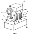
- FIG. 2 is the entire hydraulic unit shown. It can be seen the housing 10 with the longitudinal ribs 12. At one end there is the fan 30, which drives an air flow along the outside of the housing. At the opposite end of the housing is the pump part 40 with the pressure port 41 and the return port 42 on the front side. Further, there is a manometer 43 attached, which indicates the pressure.
- auxiliary reservoir 47 On an auxiliary reservoir 47 is located in a housing, the motor controller 50. This is connected to (not shown) electrical lines to the electric motor 15.
- the pressure at the pressure port 41 is determined by a (not shown) pressure sensor. This pressure is a measure of the load of the connected consumer.
- the engine controller 50 controls the electric motor 15 to reduce the engine speed at higher pressure. As soon as the pressure decreases, the engine speed increases again. In this way it is achieved that the engine absorbed power is essentially constant and largely independent of the load condition of the consumer.
Landscapes
- Engineering & Computer Science (AREA)
- Power Engineering (AREA)
- Mechanical Engineering (AREA)
- General Engineering & Computer Science (AREA)
- Motor Or Generator Cooling System (AREA)
- Supply Devices, Intensifiers, Converters, And Telemotors (AREA)
- Details Of Reciprocating Pumps (AREA)
- Fluid-Pressure Circuits (AREA)
- Auxiliary Drives, Propulsion Controls, And Safety Devices (AREA)
Claims (8)
- Groupe hydraulique pour la fourniture d'huile à une visseuse mécanique produisant une charge hydraulique, avec un réservoir (28) contenant de l'huile, une pompe et un moteur (15) électrique qui entraîne la pompe et présente un carter (10),
le moteur (15) étant un moteur synchrone entraîné avec une fréquence de fonctionnement variable, et une commande de moteur (50) étant prévue qui modifie la fréquence de fonctionnement en fonction de la charge produite par le consommateur de sorte que la fréquence de fonctionnement diminue quand la charge augmente, caractérisé en ce que
le carter (10) du moteur (15) forme en même temps au moins une partie du réservoir (28), le moteur (15) étant baigné d'huile, et en ce que, sur son côté inférieur, le carter (10) présente une plaque de montage (13) formée libre de nervures (12) et, sur son côté supérieur, un profilé de fixation (14) pour la commande de moteur. - Groupe hydraulique selon la revendication 1, caractérisé en ce que la régulation du moteur est effectuée de sorte que la puissance produite par le moteur (15) est essentiellement constante indépendamment de la grandeur de la charge.
- Groupe hydraulique selon la revendication 1 ou 2, caractérisé en ce que, pour déterminer la charge, il est prévu un capteur de pression qui mesure la pression de sortie du groupe hydraulique.
- Groupe hydraulique selon la revendication 1 ou 2, caractérisé en ce que, pour déterminer la charge, il est prévu un capteur de courant qui mesure la l'absorption de courant du moteur (15).
- Groupe hydraulique selon une des revendications 1 à 4, caractérisé en ce que, dans le carter (10), il est prévu des entretoises (26) pour le positionnement de l'enroulement du stator (18) du moteur avec une distance radiale au carter (10), de sorte que, entre l'enroulement du stator (18) et le carter (10), il est formé un espace (27) appartenant au réservoir (28).
- Groupe hydraulique selon la revendication 5, caractérisé en ce que l'enroulement du stator (18) est enserré dans une virole (25) qui est en appui sur le carter (10) sous l'action des entretoises (26).
- Groupe hydraulique selon la revendication 5, caractérisé en ce que l'espace (27) s'étend sur toute la longueur du carter (10).
- Groupe hydraulique selon une des revendications 1 à 7, caractérisé en ce que le carter (10) présente, sur son côté extérieur, des nervures (12) qui sont placées dans la direction axiale du moteur (15), et en ce que, à une extrémité du carter, il est prévu un ventilateur (30) qui fait saillie de façon radiale au-dessus du carter et qui produit un flux d'air de refroidissement (32) le long des nervures (12).
Priority Applications (1)
| Application Number | Priority Date | Filing Date | Title |
|---|---|---|---|
| PL05007830T PL1587209T3 (pl) | 2004-04-17 | 2005-04-09 | Agregat hydrauliczny dla wkrętarki |
Applications Claiming Priority (2)
| Application Number | Priority Date | Filing Date | Title |
|---|---|---|---|
| DE202004006109U DE202004006109U1 (de) | 2004-04-17 | 2004-04-17 | Hydraulikaggregat |
| DE202004006109U | 2004-04-17 |
Publications (3)
| Publication Number | Publication Date |
|---|---|
| EP1587209A2 EP1587209A2 (fr) | 2005-10-19 |
| EP1587209A3 EP1587209A3 (fr) | 2007-05-09 |
| EP1587209B1 true EP1587209B1 (fr) | 2012-12-05 |
Family
ID=32520767
Family Applications (2)
| Application Number | Title | Priority Date | Filing Date |
|---|---|---|---|
| EP05007830A Expired - Lifetime EP1587209B1 (fr) | 2004-04-17 | 2005-04-09 | Groupe hydraulique pour clé dynamomètrique |
| EP05007829A Withdrawn EP1587206A3 (fr) | 2004-04-17 | 2005-04-09 | Groupe hydraulique |
Family Applications After (1)
| Application Number | Title | Priority Date | Filing Date |
|---|---|---|---|
| EP05007829A Withdrawn EP1587206A3 (fr) | 2004-04-17 | 2005-04-09 | Groupe hydraulique |
Country Status (5)
| Country | Link |
|---|---|
| EP (2) | EP1587209B1 (fr) |
| DE (1) | DE202004006109U1 (fr) |
| DK (1) | DK1587209T3 (fr) |
| ES (1) | ES2400909T3 (fr) |
| PL (1) | PL1587209T3 (fr) |
Families Citing this family (1)
| Publication number | Priority date | Publication date | Assignee | Title |
|---|---|---|---|---|
| DE202005005165U1 (de) † | 2005-04-01 | 2006-08-17 | Wagner, Paul-Heinz | Hydraulikaggregat |
Family Cites Families (4)
| Publication number | Priority date | Publication date | Assignee | Title |
|---|---|---|---|---|
| DE3513472C2 (de) * | 1985-04-15 | 1995-04-27 | Heilmeier & Weinlein | Hydraulisches Motor-Pumpen-Aggregat |
| US5181837A (en) * | 1991-04-18 | 1993-01-26 | Vickers, Incorporated | Electric motor driven inline hydraulic apparatus |
| DE19920563A1 (de) * | 1999-05-05 | 2000-11-09 | Mannesmann Rexroth Ag | Kompaktes Hydraulikaggregat |
| US6863502B2 (en) * | 2000-04-14 | 2005-03-08 | Actuant Corporation | Variable speed hydraulic pump |
-
2004
- 2004-04-17 DE DE202004006109U patent/DE202004006109U1/de not_active Expired - Lifetime
-
2005
- 2005-04-09 PL PL05007830T patent/PL1587209T3/pl unknown
- 2005-04-09 EP EP05007830A patent/EP1587209B1/fr not_active Expired - Lifetime
- 2005-04-09 DK DK05007830.2T patent/DK1587209T3/da active
- 2005-04-09 ES ES05007830T patent/ES2400909T3/es not_active Expired - Lifetime
- 2005-04-09 EP EP05007829A patent/EP1587206A3/fr not_active Withdrawn
Also Published As
| Publication number | Publication date |
|---|---|
| EP1587209A3 (fr) | 2007-05-09 |
| DE202004006109U1 (de) | 2004-06-17 |
| DK1587209T3 (da) | 2013-02-11 |
| EP1587209A2 (fr) | 2005-10-19 |
| PL1587209T3 (pl) | 2013-04-30 |
| ES2400909T3 (es) | 2013-04-15 |
| EP1587206A3 (fr) | 2007-08-08 |
| EP1587206A2 (fr) | 2005-10-19 |
Similar Documents
| Publication | Publication Date | Title |
|---|---|---|
| DE102004003335B4 (de) | Motorölsystem mit Verstellpumpe | |
| DE3820003C2 (fr) | ||
| DE102011012586B4 (de) | Gerotorpumpe mit Außenringantrieb | |
| WO2000068572A1 (fr) | Ensemble hydraulique compact | |
| DE3005657A1 (de) | Zahnradpumpe | |
| EP2449262A1 (fr) | Pompe à plusieurs pistons | |
| EP1045143B1 (fr) | Ensemble moto-pompe hydraulique | |
| EP1495227B1 (fr) | Groupe motopompe hydraulique | |
| EP2385252B2 (fr) | Agrégat hydrophile | |
| WO2015091587A1 (fr) | Compresseur | |
| EP1587209B1 (fr) | Groupe hydraulique pour clé dynamomètrique | |
| EP2025934B1 (fr) | Assemblage de pompes et de moteurs | |
| WO1986006797A2 (fr) | Pompe a capacite variable | |
| EP0134211B1 (fr) | Dispositif de pompage pour installations hydrauliques | |
| DE2048782A1 (de) | Hydraulikanlage fur eine Maschine mit mehreren hydraulisch angetriebenen Be wegungsvornchtungen | |
| DE102007034225B4 (de) | Elektromotor für das Elektromotor-Pumpen-Aggregat eines Kraftfahrzeug-Antiblockiersystems | |
| DE1553205A1 (de) | Pump- und Abmessgeraet | |
| DE2117838A1 (de) | Elektroverdichter mit geradliniger Bewegung | |
| WO2015185179A1 (fr) | Unité motopompe à commande électrique | |
| EP2157318A2 (fr) | Dispositif d'alimentation hydraulique | |
| DE3314651C2 (de) | Vakuumpumpe | |
| AT251365B (de) | Steuerorgan für hydrostatische Einheiten | |
| DE102022117052A1 (de) | Elektro-hydraulisches Antriebssystem | |
| DE10352029A1 (de) | Verdrängerpumpe mit Vorladeeinrichtung | |
| DE2026528A1 (de) | Umwälzpumpe mit kontinuierlich ver stellbarer Pumpleistung |
Legal Events
| Date | Code | Title | Description |
|---|---|---|---|
| PUAI | Public reference made under article 153(3) epc to a published international application that has entered the european phase |
Free format text: ORIGINAL CODE: 0009012 |
|
| AK | Designated contracting states |
Kind code of ref document: A2 Designated state(s): AT BE BG CH CY CZ DE DK EE ES FI FR GB GR HU IE IS IT LI LT LU MC NL PL PT RO SE SI SK TR |
|
| AX | Request for extension of the european patent |
Extension state: AL BA HR LV MK YU |
|
| PUAL | Search report despatched |
Free format text: ORIGINAL CODE: 0009013 |
|
| AK | Designated contracting states |
Kind code of ref document: A3 Designated state(s): AT BE BG CH CY CZ DE DK EE ES FI FR GB GR HU IE IS IT LI LT LU MC NL PL PT RO SE SI SK TR |
|
| AX | Request for extension of the european patent |
Extension state: AL BA HR LV MK YU |
|
| 17P | Request for examination filed |
Effective date: 20070706 |
|
| 17Q | First examination report despatched |
Effective date: 20070903 |
|
| AKX | Designation fees paid |
Designated state(s): AT BE BG CH CY CZ DE DK EE ES FI FR GB GR HU IE IS IT LI LT LU MC NL PL PT RO SE SI SK TR |
|
| RAP1 | Party data changed (applicant data changed or rights of an application transferred) |
Owner name: WAGNER VERMOEGENSVERWALTUNGS-GMBH & CO. KG |
|
| GRAP | Despatch of communication of intention to grant a patent |
Free format text: ORIGINAL CODE: EPIDOSNIGR1 |
|
| GRAS | Grant fee paid |
Free format text: ORIGINAL CODE: EPIDOSNIGR3 |
|
| GRAA | (expected) grant |
Free format text: ORIGINAL CODE: 0009210 |
|
| AK | Designated contracting states |
Kind code of ref document: B1 Designated state(s): AT BE BG CH CY CZ DE DK EE ES FI FR GB GR HU IE IS IT LI LT LU MC NL PL PT RO SE SI SK TR |
|
| REG | Reference to a national code |
Ref country code: GB Ref legal event code: FG4D Free format text: NOT ENGLISH |
|
| REG | Reference to a national code |
Ref country code: CH Ref legal event code: EP |
|
| REG | Reference to a national code |
Ref country code: AT Ref legal event code: REF Ref document number: 587734 Country of ref document: AT Kind code of ref document: T Effective date: 20121215 |
|
| REG | Reference to a national code |
Ref country code: IE Ref legal event code: FG4D Free format text: LANGUAGE OF EP DOCUMENT: GERMAN |
|
| REG | Reference to a national code |
Ref country code: DE Ref legal event code: R096 Ref document number: 502005013310 Country of ref document: DE Effective date: 20130131 |
|
| REG | Reference to a national code |
Ref country code: DK Ref legal event code: T3 |
|
| REG | Reference to a national code |
Ref country code: ES Ref legal event code: FG2A Ref document number: 2400909 Country of ref document: ES Kind code of ref document: T3 Effective date: 20130415 |
|
| PG25 | Lapsed in a contracting state [announced via postgrant information from national office to epo] |
Ref country code: SE Free format text: LAPSE BECAUSE OF FAILURE TO SUBMIT A TRANSLATION OF THE DESCRIPTION OR TO PAY THE FEE WITHIN THE PRESCRIBED TIME-LIMIT Effective date: 20121205 Ref country code: FI Free format text: LAPSE BECAUSE OF FAILURE TO SUBMIT A TRANSLATION OF THE DESCRIPTION OR TO PAY THE FEE WITHIN THE PRESCRIBED TIME-LIMIT Effective date: 20121205 Ref country code: LT Free format text: LAPSE BECAUSE OF FAILURE TO SUBMIT A TRANSLATION OF THE DESCRIPTION OR TO PAY THE FEE WITHIN THE PRESCRIBED TIME-LIMIT Effective date: 20121205 |
|
| REG | Reference to a national code |
Ref country code: PL Ref legal event code: T3 |
|
| REG | Reference to a national code |
Ref country code: NL Ref legal event code: VDEP Effective date: 20121205 |
|
| REG | Reference to a national code |
Ref country code: LT Ref legal event code: MG4D |
|
| PG25 | Lapsed in a contracting state [announced via postgrant information from national office to epo] |
Ref country code: SI Free format text: LAPSE BECAUSE OF FAILURE TO SUBMIT A TRANSLATION OF THE DESCRIPTION OR TO PAY THE FEE WITHIN THE PRESCRIBED TIME-LIMIT Effective date: 20121205 Ref country code: GR Free format text: LAPSE BECAUSE OF FAILURE TO SUBMIT A TRANSLATION OF THE DESCRIPTION OR TO PAY THE FEE WITHIN THE PRESCRIBED TIME-LIMIT Effective date: 20130306 Ref country code: CY Free format text: LAPSE BECAUSE OF FAILURE TO SUBMIT A TRANSLATION OF THE DESCRIPTION OR TO PAY THE FEE WITHIN THE PRESCRIBED TIME-LIMIT Effective date: 20121205 |
|
| PG25 | Lapsed in a contracting state [announced via postgrant information from national office to epo] |
Ref country code: SK Free format text: LAPSE BECAUSE OF FAILURE TO SUBMIT A TRANSLATION OF THE DESCRIPTION OR TO PAY THE FEE WITHIN THE PRESCRIBED TIME-LIMIT Effective date: 20121205 Ref country code: BG Free format text: LAPSE BECAUSE OF FAILURE TO SUBMIT A TRANSLATION OF THE DESCRIPTION OR TO PAY THE FEE WITHIN THE PRESCRIBED TIME-LIMIT Effective date: 20130305 Ref country code: IS Free format text: LAPSE BECAUSE OF FAILURE TO SUBMIT A TRANSLATION OF THE DESCRIPTION OR TO PAY THE FEE WITHIN THE PRESCRIBED TIME-LIMIT Effective date: 20130405 Ref country code: EE Free format text: LAPSE BECAUSE OF FAILURE TO SUBMIT A TRANSLATION OF THE DESCRIPTION OR TO PAY THE FEE WITHIN THE PRESCRIBED TIME-LIMIT Effective date: 20121205 Ref country code: CZ Free format text: LAPSE BECAUSE OF FAILURE TO SUBMIT A TRANSLATION OF THE DESCRIPTION OR TO PAY THE FEE WITHIN THE PRESCRIBED TIME-LIMIT Effective date: 20121205 |
|
| PG25 | Lapsed in a contracting state [announced via postgrant information from national office to epo] |
Ref country code: RO Free format text: LAPSE BECAUSE OF FAILURE TO SUBMIT A TRANSLATION OF THE DESCRIPTION OR TO PAY THE FEE WITHIN THE PRESCRIBED TIME-LIMIT Effective date: 20121205 Ref country code: PT Free format text: LAPSE BECAUSE OF FAILURE TO SUBMIT A TRANSLATION OF THE DESCRIPTION OR TO PAY THE FEE WITHIN THE PRESCRIBED TIME-LIMIT Effective date: 20130405 Ref country code: NL Free format text: LAPSE BECAUSE OF FAILURE TO SUBMIT A TRANSLATION OF THE DESCRIPTION OR TO PAY THE FEE WITHIN THE PRESCRIBED TIME-LIMIT Effective date: 20121205 |
|
| PLBE | No opposition filed within time limit |
Free format text: ORIGINAL CODE: 0009261 |
|
| STAA | Information on the status of an ep patent application or granted ep patent |
Free format text: STATUS: NO OPPOSITION FILED WITHIN TIME LIMIT |
|
| BERE | Be: lapsed |
Owner name: WAGNER VERMOGENSVERWALTUNGS-GMBH & CO. K.G. Effective date: 20130430 |
|
| 26N | No opposition filed |
Effective date: 20130906 |
|
| PG25 | Lapsed in a contracting state [announced via postgrant information from national office to epo] |
Ref country code: MC Free format text: LAPSE BECAUSE OF FAILURE TO SUBMIT A TRANSLATION OF THE DESCRIPTION OR TO PAY THE FEE WITHIN THE PRESCRIBED TIME-LIMIT Effective date: 20121205 |
|
| REG | Reference to a national code |
Ref country code: CH Ref legal event code: PL |
|
| REG | Reference to a national code |
Ref country code: DE Ref legal event code: R097 Ref document number: 502005013310 Country of ref document: DE Effective date: 20130906 |
|
| REG | Reference to a national code |
Ref country code: IE Ref legal event code: MM4A |
|
| PG25 | Lapsed in a contracting state [announced via postgrant information from national office to epo] |
Ref country code: CH Free format text: LAPSE BECAUSE OF NON-PAYMENT OF DUE FEES Effective date: 20130430 Ref country code: BE Free format text: LAPSE BECAUSE OF NON-PAYMENT OF DUE FEES Effective date: 20130430 Ref country code: LI Free format text: LAPSE BECAUSE OF NON-PAYMENT OF DUE FEES Effective date: 20130430 |
|
| PG25 | Lapsed in a contracting state [announced via postgrant information from national office to epo] |
Ref country code: IE Free format text: LAPSE BECAUSE OF NON-PAYMENT OF DUE FEES Effective date: 20130409 |
|
| REG | Reference to a national code |
Ref country code: AT Ref legal event code: MM01 Ref document number: 587734 Country of ref document: AT Kind code of ref document: T Effective date: 20130409 |
|
| PG25 | Lapsed in a contracting state [announced via postgrant information from national office to epo] |
Ref country code: AT Free format text: LAPSE BECAUSE OF NON-PAYMENT OF DUE FEES Effective date: 20130409 |
|
| REG | Reference to a national code |
Ref country code: FR Ref legal event code: PLFP Year of fee payment: 11 |
|
| PG25 | Lapsed in a contracting state [announced via postgrant information from national office to epo] |
Ref country code: LU Free format text: LAPSE BECAUSE OF NON-PAYMENT OF DUE FEES Effective date: 20130409 Ref country code: HU Free format text: LAPSE BECAUSE OF FAILURE TO SUBMIT A TRANSLATION OF THE DESCRIPTION OR TO PAY THE FEE WITHIN THE PRESCRIBED TIME-LIMIT; INVALID AB INITIO Effective date: 20050409 |
|
| REG | Reference to a national code |
Ref country code: FR Ref legal event code: PLFP Year of fee payment: 12 |
|
| PGFP | Annual fee paid to national office [announced via postgrant information from national office to epo] |
Ref country code: TR Payment date: 20160330 Year of fee payment: 12 |
|
| REG | Reference to a national code |
Ref country code: FR Ref legal event code: PLFP Year of fee payment: 13 |
|
| REG | Reference to a national code |
Ref country code: FR Ref legal event code: PLFP Year of fee payment: 14 |
|
| PG25 | Lapsed in a contracting state [announced via postgrant information from national office to epo] |
Ref country code: TR Free format text: LAPSE BECAUSE OF NON-PAYMENT OF DUE FEES Effective date: 20170409 |
|
| PGFP | Annual fee paid to national office [announced via postgrant information from national office to epo] |
Ref country code: PL Payment date: 20240327 Year of fee payment: 20 |
|
| PGFP | Annual fee paid to national office [announced via postgrant information from national office to epo] |
Ref country code: GB Payment date: 20240423 Year of fee payment: 20 |
|
| PGFP | Annual fee paid to national office [announced via postgrant information from national office to epo] |
Ref country code: DE Payment date: 20240416 Year of fee payment: 20 |
|
| PGFP | Annual fee paid to national office [announced via postgrant information from national office to epo] |
Ref country code: DK Payment date: 20240422 Year of fee payment: 20 |
|
| PGFP | Annual fee paid to national office [announced via postgrant information from national office to epo] |
Ref country code: ES Payment date: 20240517 Year of fee payment: 20 |
|
| PGFP | Annual fee paid to national office [announced via postgrant information from national office to epo] |
Ref country code: IT Payment date: 20240430 Year of fee payment: 20 Ref country code: FR Payment date: 20240422 Year of fee payment: 20 |
|
| REG | Reference to a national code |
Ref country code: DE Ref legal event code: R071 Ref document number: 502005013310 Country of ref document: DE |
|
| REG | Reference to a national code |
Ref country code: DK Ref legal event code: EUP Expiry date: 20250409 |
|
| REG | Reference to a national code |
Ref country code: GB Ref legal event code: PE20 Expiry date: 20250408 Ref country code: ES Ref legal event code: FD2A Effective date: 20250430 |
|
| PG25 | Lapsed in a contracting state [announced via postgrant information from national office to epo] |
Ref country code: GB Free format text: LAPSE BECAUSE OF EXPIRATION OF PROTECTION Effective date: 20250408 Ref country code: ES Free format text: LAPSE BECAUSE OF EXPIRATION OF PROTECTION Effective date: 20250410 |