EP1588021B1 - Verfahren und vorrichtung zum bohren von in ineinander angeordneten rohren - Google Patents
Verfahren und vorrichtung zum bohren von in ineinander angeordneten rohren Download PDFInfo
- Publication number
- EP1588021B1 EP1588021B1 EP04701709A EP04701709A EP1588021B1 EP 1588021 B1 EP1588021 B1 EP 1588021B1 EP 04701709 A EP04701709 A EP 04701709A EP 04701709 A EP04701709 A EP 04701709A EP 1588021 B1 EP1588021 B1 EP 1588021B1
- Authority
- EP
- European Patent Office
- Prior art keywords
- feed
- drill bit
- drilling
- pressure fluid
- valve
- Prior art date
- Legal status (The legal status is an assumption and is not a legal conclusion. Google has not performed a legal analysis and makes no representation as to the accuracy of the status listed.)
- Expired - Lifetime
Links
- 238000005553 drilling Methods 0.000 title claims abstract description 45
- 238000000034 method Methods 0.000 title claims abstract description 11
- 239000012530 fluid Substances 0.000 claims abstract description 22
- 239000000463 material Substances 0.000 claims abstract description 13
- 230000001105 regulatory effect Effects 0.000 claims abstract description 8
- 230000004941 influx Effects 0.000 claims abstract 3
- XLYOFNOQVPJJNP-UHFFFAOYSA-N water Substances O XLYOFNOQVPJJNP-UHFFFAOYSA-N 0.000 claims 1
- 230000008878 coupling Effects 0.000 description 8
- 238000010168 coupling process Methods 0.000 description 8
- 238000005859 coupling reaction Methods 0.000 description 8
- 239000002131 composite material Substances 0.000 description 1
- 238000010586 diagram Methods 0.000 description 1
- 238000006073 displacement reaction Methods 0.000 description 1
- 230000001788 irregular Effects 0.000 description 1
- 238000004391 petroleum recovery Methods 0.000 description 1
Images


Classifications
-
- E—FIXED CONSTRUCTIONS
- E21—EARTH OR ROCK DRILLING; MINING
- E21B—EARTH OR ROCK DRILLING; OBTAINING OIL, GAS, WATER, SOLUBLE OR MELTABLE MATERIALS OR A SLURRY OF MINERALS FROM WELLS
- E21B29/00—Cutting or destroying pipes, packers, plugs or wire lines, located in boreholes or wells, e.g. cutting of damaged pipes, of windows; Deforming of pipes in boreholes or wells; Reconditioning of well casings while in the ground
- E21B29/002—Cutting, e.g. milling, a pipe with a cutter rotating along the circumference of the pipe
-
- E—FIXED CONSTRUCTIONS
- E21—EARTH OR ROCK DRILLING; MINING
- E21B—EARTH OR ROCK DRILLING; OBTAINING OIL, GAS, WATER, SOLUBLE OR MELTABLE MATERIALS OR A SLURRY OF MINERALS FROM WELLS
- E21B44/00—Automatic control systems specially adapted for drilling operations, i.e. self-operating systems which function to carry out or modify a drilling operation without intervention of a human operator, e.g. computer-controlled drilling systems; Systems specially adapted for monitoring a plurality of drilling variables or conditions
- E21B44/02—Automatic control of the tool feed
- E21B44/04—Automatic control of the tool feed in response to the torque of the drive ; Measuring drilling torque
Definitions
- This invention relates to a method for drilling into tubulars which are located within one another. More specifically, it relates to a method for reducing drilling time when drilling through at least one pipe wall and there in an annulus within the pipe wall is a fluid or a material which in comparison to the pipe wall material is easier to drill.
- the invention also comprises a device for carrying out the method.
- the internal pipes may become displaced axially and/or radially in relation to the external pipe during the sawing operation. The displacement may cause damage to the sawing device that is being used.
- one or more drilling devices are placeded mainly in a radial direction on the casing surface of the external pipe.
- the drilling device may be hydraulically driven with regards to both rotation and feeding.
- the drill bit of the drilling device is fed at a certain rate when rotating through the external pipe, the material located in the external annulus, and potentially further on through the pipe within, the next annulus and so on till the innermost pipe where the drill can be used for bracing by means of the feed power or for drilling through the pipe wall of the innermost pipe as well. Then, the drill may be used for bracing or it may be replaced with for instance a shaft to brace the pipes.
- Drilling operations in accordance with prior art take unnecessary long time because the drill is running at an approximately constant feed speed during the entire drilling operation.
- the object of this invention is to remedy the disadvantages of the prior art.
- the drill bit can be fed at a significantly higher rate when it is working for example within concrete, compared to the feed speed which is appropriate for drilling in the pipe wall material.
- a valve for additional supply of hydraulic fluid to the feed cylinders of the drilling device is opened without disrupting the choke valve or constant pressure valve that is used to adjust the feed speed of the sawing device for drilling through the pipe wall material.
- the rotational resistance of the drill is then increased, and a corresponding higher pressure can be read in the hydraulic circuit for drill bit rotation.
- the additional pressure fluid supply is shut off, whereby the drill bit continues to drill through the pipe wall material at the preset feed speed.
- the method is repeated for any annuli and pipe walls located within.
- the drilling time for perforating pipes containing other pipes within can be significantly reduced.
- the method may contribute to considerable cost savings, as the hourly rates for this type of work, including hiring a drilling rig, are relatively high.
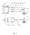
- the reference number 1 denotes a drilling device provided with a drill bit 2 which is secured to an external tubular 6 by means of a fastening device 4.
- the spaces between the tubulars 6, 8 and 10 constitute an external annulus 12 and an internal annulus 14.
- the annuli 12 and 14 are filled with concrete.
- the drilling device 1 comprises a feed rod 22 which is connected to the drill bit 2 by means of an adapter 20.
- the feed rod 22 is axially displaceable in the housing 24 of the drilling device 1 by means of two feed cylinders 26.
- the feed cylinders 26 are connected between the housing 24 and an axial bearing 28 placed around the feed rod 22.
- Two hydraulic driving motors 30 are connected to the housing 24 and encircle the feed rod 22 in an axially displaceable manner.
- the drilling device 1 is controlled by means of a rotary valve 40 and a feed valve 42.
- the valves 40 and 42 are located at a safe distance from the drilling device 1 and supplied with pressure fluid from a hydraulic pump (not shown). From the rotary valve 40 hydraulic pipes 44 pass via quick release couplings 46 to the driving motors 30.
- a hydraulic feed line 48 connects the feed valve 42 via a quick release coupling 50 and a choke valve 52 to the feed side of the feed cylinders 26.
- the return side of the feed cylinders 26 is connected to the feed valve 42 by means of a hydraulic return line 54 and a quick release coupling 56.
- a quick feed valve 58 is connected to the hydraulic feed line 48 at the feed valve 42. From the quick feed valve 58, a quick feed hydraulic line 60 passes via a quick release coupling 62 to the hydraulic feed line 48 in the area between the choke valve 52 and the feed cylinders 26.
- the quick release couplings 46, 50, 56 and 62 are arranged to facilitate the assembly of the drilling device 1.
- the desired feed speed for the drill bit 2 is adjusted by regulating the choke valve 52, preferably before the drilling operations commence.
- the rotation of the drill bit 2 is initiated by setting the rotary valve 40 to operating position. Pressure fluid then flows through the rotary valve 40 and the driving motors 30 via the hydraulic lines 44 and the quick release couplings 46.
- the driving motors 30 rotate the feed rod 22 and thus the drill bit 2 around its own longitudinal axis.
- the feeding of the drill bit 2 is initiated by setting the feed valve 42 to its feeding position. By doing so, pressure fluid flows from the feed valve 42 via the hydraulic feed line 48, the quick release coupling 50 and the choke valve 42 to the feed side of the feed cylinders, as the feed cylinders displace the axial bearing 28 and thus the feed rod 22 and the drill bit 2 in a direction in and towards the external tubular 6.
- the quick feed valve 58 By opening the quick feed valve 58, pressure fluid flows to the feed side of the feed cylinders 26 through the hydraulic quick feed line 60 and the quick release coupling 62 bypassing the choke valve 52.
- the drill bit 2 is fed quicker through the concrete in the external annulus 12, cf. the drill bit 2 belonging to the lower drilling device in figure 1.
- the rotational resistance in the drill bit 2 is increased.
- the corresponding increase in pressure can be read from the manometer 64.
- the quick feed valve 58 is shut, whereby the feed speed of the drill bit 2 through the pipe wall of the intermediate tubular 8 is reduced to the preset value on the choke valve 52.
- the feed speed is increased when drilling through the internal annulus 14 and possibly through the annulus of the internal pipe 10.
Landscapes
- Geology (AREA)
- Life Sciences & Earth Sciences (AREA)
- Engineering & Computer Science (AREA)
- Mining & Mineral Resources (AREA)
- Environmental & Geological Engineering (AREA)
- Fluid Mechanics (AREA)
- Physics & Mathematics (AREA)
- General Life Sciences & Earth Sciences (AREA)
- Geochemistry & Mineralogy (AREA)
- Earth Drilling (AREA)
- Processing Of Stones Or Stones Resemblance Materials (AREA)
- Drilling And Boring (AREA)
- Punching Or Piercing (AREA)
- Perforating, Stamping-Out Or Severing By Means Other Than Cutting (AREA)
Claims (4)
- Verfahren für eine Bohrvorrichtung (1) zum Erhöhen der Zufuhrgeschwindigkeit einer Bohrspitze (2) beim Bohren durch ineinander angeordnete Rohre (6, 8, 10), in den zwischen den Rohren erzeugten Ringen (12, 14) befindet sich ein Fluid oder Material, welches im Vergleich zum Rohrwandmaterial leichter zu bohren ist, die Zufuhrgeschwindigkeit der Bohrspitze (2) wird durch ein vorzugsweise benachbart der Bohrvorrichtung (2) angeordnetes Fluiddruckregelventil (52) gesteuert, dadurch gekennzeichnet, dass während des Vortriebs der Bohrspitze (2) durch die Ringe (12, 14) ein Zustrom von Druckfluid parallel zum Fluiddruckregelventil (52) erfolgt.
- Verfahren nach Anspruch 1, dadurch gekennzeichnet, dass der Zustrom von Druckfluid durch Öffnen eines in sicherer Entfernung von der Bohrvorrichtung (1) angeordneten Ventils (58) eingeleitet wird.
- Vorrichtung für eine Bohrvorrichtung (1) zum Erhöhen der Zufuhrgeschwindigkeit einer Bohrspitze (2) beim Bohren durch ineinander angeordnete Rohre (6, 8, 10), in den zwischen den Rohren erzeugten Ringen (12, 14) befindet sich ein Fluid oder Material, welches im Vergleich zum Rohrwandmaterial leichter zu bohren ist, die Zufuhrgeschwindigkeit der Bohrspitze (2) wird durch ein mit einer Hydraulik-Speiseleitung (48) verbundenes Fluiddruckregelventil (52) gesteuert, wobei die Hydraulik-Zufuhrleitung (48) von einem Speiseventil (42) zu einem Zufuhrzylinder (26) verläuft, und wobei das Fluiddruckregelventil (52) vorzugsweise benachbart der Bohrvorrichtung (2) angeordnet ist, dadurch gekennzeichnet, dass eine mit einem Absperrventil (58) versehene, parallel zur Hydraulik-Zufuhrleitung (48) verlaufende und oberhalb und unterhalb des Fluiddruckregelventils (52) mit dieser verbundene Hydraulik-Schnellzufuhrleitung (60) vorgesehen ist.
- Vorrichtung nach Anspruch 3, dadurch gekennzeichnet, dass das Absperrventil (58) in sicherer Entfernung von der Bohrvorrichtung (1) angeordnet ist.
Applications Claiming Priority (3)
| Application Number | Priority Date | Filing Date | Title |
|---|---|---|---|
| NO20030149A NO317433B1 (no) | 2003-01-13 | 2003-01-13 | Fremgangsmate og anordning for boring i inne i hverandre seg befinnende ror |
| FI20030149 | 2003-01-13 | ||
| PCT/NO2004/000005 WO2004063525A1 (en) | 2003-01-13 | 2004-01-13 | A method and device for drilling into tubulars located within one another |
Publications (2)
| Publication Number | Publication Date |
|---|---|
| EP1588021A1 EP1588021A1 (de) | 2005-10-26 |
| EP1588021B1 true EP1588021B1 (de) | 2006-08-02 |
Family
ID=19914372
Family Applications (1)
| Application Number | Title | Priority Date | Filing Date |
|---|---|---|---|
| EP04701709A Expired - Lifetime EP1588021B1 (de) | 2003-01-13 | 2004-01-13 | Verfahren und vorrichtung zum bohren von in ineinander angeordneten rohren |
Country Status (8)
| Country | Link |
|---|---|
| US (1) | US20060231291A1 (de) |
| EP (1) | EP1588021B1 (de) |
| AT (1) | ATE335122T1 (de) |
| BR (1) | BRPI0406732A (de) |
| DE (1) | DE602004001756D1 (de) |
| DK (1) | DK1588021T3 (de) |
| NO (1) | NO317433B1 (de) |
| WO (1) | WO2004063525A1 (de) |
Cited By (2)
| Publication number | Priority date | Publication date | Assignee | Title |
|---|---|---|---|---|
| US8869916B2 (en) | 2010-09-09 | 2014-10-28 | National Oilwell Varco, L.P. | Rotary steerable push-the-bit drilling apparatus with self-cleaning fluid filter |
| US9016400B2 (en) | 2010-09-09 | 2015-04-28 | National Oilwell Varco, L.P. | Downhole rotary drilling apparatus with formation-interfacing members and control system |
Families Citing this family (3)
| Publication number | Priority date | Publication date | Assignee | Title |
|---|---|---|---|---|
| US7946793B2 (en) | 2008-03-28 | 2011-05-24 | Fastorq, Llc | Apparatus for drilling colinear holes through concentric pipes |
| CN103406939B (zh) * | 2013-07-19 | 2016-03-30 | 广东联塑科技实业有限公司 | 一种pvc渗漏管制作装置 |
| US12460516B1 (en) * | 2020-12-09 | 2025-11-04 | Roscoe Moss Manufacturing Company | System, apparatus, and method for louver perforation |
Family Cites Families (11)
| Publication number | Priority date | Publication date | Assignee | Title |
|---|---|---|---|---|
| US3903697A (en) * | 1974-07-24 | 1975-09-09 | Azcon Corp | Variable speed hydraulic drive |
| US4271914A (en) * | 1976-12-02 | 1981-06-09 | The United States Of America As Represented By The Secretary Of The Interior | Automatic feed and rotational speed control system of a hydraulic motor operated drill |
| US4185652A (en) * | 1977-10-31 | 1980-01-29 | Nl Industries, Inc. | Subaqueous sequence valve mechanism |
| US4226288A (en) * | 1978-05-05 | 1980-10-07 | California Institute Of Technology | Side hole drilling in boreholes |
| US4619556A (en) * | 1983-11-14 | 1986-10-28 | Parra Ernest P | Method and apparatus for severing a tubular member |
| US5392858A (en) * | 1994-04-15 | 1995-02-28 | Penetrators, Inc. | Milling apparatus and method for well casing |
| US5564455A (en) * | 1995-01-06 | 1996-10-15 | The Charles Machine Works, Inc. | Hydraulic circuit for automatic control of a horizontal boring machine |
| US5687806A (en) * | 1996-02-20 | 1997-11-18 | Gas Research Institute | Method and apparatus for drilling with a flexible shaft while using hydraulic assistance |
| US6155343A (en) * | 1996-10-25 | 2000-12-05 | Baker Hughes Incorporated | System for cutting materials in wellbores |
| US6167968B1 (en) * | 1998-05-05 | 2001-01-02 | Penetrators Canada, Inc. | Method and apparatus for radially drilling through well casing and formation |
| DE19924200B4 (de) * | 1999-05-27 | 2004-07-15 | Wolfgang Schmidt E.K. | Drehzahl-Vorschubregelung |
-
2003
- 2003-01-13 NO NO20030149A patent/NO317433B1/no not_active IP Right Cessation
-
2004
- 2004-01-13 WO PCT/NO2004/000005 patent/WO2004063525A1/en not_active Ceased
- 2004-01-13 AT AT04701709T patent/ATE335122T1/de not_active IP Right Cessation
- 2004-01-13 BR BR0406732-0A patent/BRPI0406732A/pt not_active IP Right Cessation
- 2004-01-13 US US10/541,835 patent/US20060231291A1/en not_active Abandoned
- 2004-01-13 DE DE602004001756T patent/DE602004001756D1/de not_active Expired - Lifetime
- 2004-01-13 EP EP04701709A patent/EP1588021B1/de not_active Expired - Lifetime
- 2004-01-13 DK DK04701709T patent/DK1588021T3/da active
Cited By (3)
| Publication number | Priority date | Publication date | Assignee | Title |
|---|---|---|---|---|
| US8869916B2 (en) | 2010-09-09 | 2014-10-28 | National Oilwell Varco, L.P. | Rotary steerable push-the-bit drilling apparatus with self-cleaning fluid filter |
| US9016400B2 (en) | 2010-09-09 | 2015-04-28 | National Oilwell Varco, L.P. | Downhole rotary drilling apparatus with formation-interfacing members and control system |
| US9476263B2 (en) | 2010-09-09 | 2016-10-25 | National Oilwell Varco, L.P. | Rotary steerable push-the-bit drilling apparatus with self-cleaning fluid filter |
Also Published As
| Publication number | Publication date |
|---|---|
| ATE335122T1 (de) | 2006-08-15 |
| US20060231291A1 (en) | 2006-10-19 |
| WO2004063525A1 (en) | 2004-07-29 |
| EP1588021A1 (de) | 2005-10-26 |
| DE602004001756D1 (de) | 2006-09-14 |
| NO20030149D0 (no) | 2003-01-13 |
| NO317433B1 (no) | 2004-10-25 |
| DK1588021T3 (da) | 2006-12-04 |
| BRPI0406732A (pt) | 2005-12-20 |
Similar Documents
| Publication | Publication Date | Title |
|---|---|---|
| US6679328B2 (en) | Reverse section milling method and apparatus | |
| US6564868B1 (en) | Cutting tool and method for cutting tubular member | |
| EP1015729B1 (de) | Verbindung von rohrförmigen elementen mit anwendung einer oberantriebseinrichtung | |
| NO309994B1 (no) | FremgangsmÕte og anordning for anbringelse av en ledekile | |
| US3799277A (en) | Force applicator | |
| US4785885A (en) | Method and apparatus for cementing a production conduit within an underground arcuate bore | |
| EP3341559B1 (de) | Abdichten und steuern eines fluiddrucks in einem ringförmigen fluiddurchgang in einem bohrlochprozess | |
| NO325359B1 (no) | Fremgangsmate og anordning for a bevege et ror i borehull i grunnen | |
| NO327553B1 (no) | Fremgangsmate og sammenstilling for okning av borekapasitet og fjerning av borkaks under boring av avviksborehull med spoleror | |
| WO2016116910A1 (en) | Shaft enlargement arrangement for a boring system | |
| KR20130007556A (ko) | 연속 공구회전과 연속 천공액 공급을 수반하는 굴착장치 및 방법 | |
| EP2818626A1 (de) | Verbessertes Verfahren und Vorrichtung zur Herstellung von seitlichen Öffnungen aus einem Bohrloch | |
| EP1588021B1 (de) | Verfahren und vorrichtung zum bohren von in ineinander angeordneten rohren | |
| EP0233038A2 (de) | Bohrvorrichtung im Bohrloch | |
| AU2004204324B2 (en) | A method and device for drilling into tubulars located within one another | |
| CN101126304A (zh) | 一种隔水套管安装方法——沉管钻入法 | |
| US4076087A (en) | Hole reamer | |
| US20130306376A1 (en) | Pressure balanced fluid operated reaming tool for use in placing wellbore tubulars | |
| CA3028432A1 (en) | Drill assembly and valve | |
| US20210207448A1 (en) | Apparatus for Downhole Milling of Material of a Well Wall | |
| CA1138420A (en) | Raise drill apparatus | |
| CN118241986A (zh) | 一种防塌孔的水力压裂钻孔装置 | |
| US1910890A (en) | Hydraulic feed for rotary drills | |
| US20180128068A1 (en) | Air Storage System | |
| RU2230183C1 (ru) | Устройство для перфорации обсаженной скважины (варианты) |
Legal Events
| Date | Code | Title | Description |
|---|---|---|---|
| PUAI | Public reference made under article 153(3) epc to a published international application that has entered the european phase |
Free format text: ORIGINAL CODE: 0009012 |
|
| 17P | Request for examination filed |
Effective date: 20050804 |
|
| AK | Designated contracting states |
Kind code of ref document: A1 Designated state(s): AT BE BG CH CY CZ DE DK EE ES FI FR GB GR HU IE IT LI LU MC NL PT RO SE SI SK TR |
|
| AX | Request for extension of the european patent |
Extension state: AL LT LV MK |
|
| GRAP | Despatch of communication of intention to grant a patent |
Free format text: ORIGINAL CODE: EPIDOSNIGR1 |
|
| DAX | Request for extension of the european patent (deleted) | ||
| GRAS | Grant fee paid |
Free format text: ORIGINAL CODE: EPIDOSNIGR3 |
|
| GRAA | (expected) grant |
Free format text: ORIGINAL CODE: 0009210 |
|
| AK | Designated contracting states |
Kind code of ref document: B1 Designated state(s): AT BE BG CH CY CZ DE DK EE ES FI FR GB GR HU IE IT LI LU MC NL PT RO SE SI SK TR |
|
| PG25 | Lapsed in a contracting state [announced via postgrant information from national office to epo] |
Ref country code: IT Free format text: LAPSE BECAUSE OF FAILURE TO SUBMIT A TRANSLATION OF THE DESCRIPTION OR TO PAY THE FEE WITHIN THE PRESCRIBED TIME-LIMIT;WARNING: LAPSES OF ITALIAN PATENTS WITH EFFECTIVE DATE BEFORE 2007 MAY HAVE OCCURRED AT ANY TIME BEFORE 2007. THE CORRECT EFFECTIVE DATE MAY BE DIFFERENT FROM THE ONE RECORDED. Effective date: 20060802 Ref country code: FI Free format text: LAPSE BECAUSE OF FAILURE TO SUBMIT A TRANSLATION OF THE DESCRIPTION OR TO PAY THE FEE WITHIN THE PRESCRIBED TIME-LIMIT Effective date: 20060802 Ref country code: SK Free format text: LAPSE BECAUSE OF FAILURE TO SUBMIT A TRANSLATION OF THE DESCRIPTION OR TO PAY THE FEE WITHIN THE PRESCRIBED TIME-LIMIT Effective date: 20060802 Ref country code: CH Free format text: LAPSE BECAUSE OF FAILURE TO SUBMIT A TRANSLATION OF THE DESCRIPTION OR TO PAY THE FEE WITHIN THE PRESCRIBED TIME-LIMIT Effective date: 20060802 Ref country code: CZ Free format text: LAPSE BECAUSE OF FAILURE TO SUBMIT A TRANSLATION OF THE DESCRIPTION OR TO PAY THE FEE WITHIN THE PRESCRIBED TIME-LIMIT Effective date: 20060802 Ref country code: AT Free format text: LAPSE BECAUSE OF FAILURE TO SUBMIT A TRANSLATION OF THE DESCRIPTION OR TO PAY THE FEE WITHIN THE PRESCRIBED TIME-LIMIT Effective date: 20060802 Ref country code: LI Free format text: LAPSE BECAUSE OF FAILURE TO SUBMIT A TRANSLATION OF THE DESCRIPTION OR TO PAY THE FEE WITHIN THE PRESCRIBED TIME-LIMIT Effective date: 20060802 Ref country code: RO Free format text: LAPSE BECAUSE OF FAILURE TO SUBMIT A TRANSLATION OF THE DESCRIPTION OR TO PAY THE FEE WITHIN THE PRESCRIBED TIME-LIMIT Effective date: 20060802 Ref country code: BE Free format text: LAPSE BECAUSE OF FAILURE TO SUBMIT A TRANSLATION OF THE DESCRIPTION OR TO PAY THE FEE WITHIN THE PRESCRIBED TIME-LIMIT Effective date: 20060802 Ref country code: SI Free format text: LAPSE BECAUSE OF FAILURE TO SUBMIT A TRANSLATION OF THE DESCRIPTION OR TO PAY THE FEE WITHIN THE PRESCRIBED TIME-LIMIT Effective date: 20060802 |
|
| REG | Reference to a national code |
Ref country code: GB Ref legal event code: FG4D |
|
| REG | Reference to a national code |
Ref country code: CH Ref legal event code: EP |
|
| REG | Reference to a national code |
Ref country code: IE Ref legal event code: FG4D |
|
| REF | Corresponds to: |
Ref document number: 602004001756 Country of ref document: DE Date of ref document: 20060914 Kind code of ref document: P |
|
| PG25 | Lapsed in a contracting state [announced via postgrant information from national office to epo] |
Ref country code: BG Free format text: LAPSE BECAUSE OF FAILURE TO SUBMIT A TRANSLATION OF THE DESCRIPTION OR TO PAY THE FEE WITHIN THE PRESCRIBED TIME-LIMIT Effective date: 20061102 Ref country code: SE Free format text: LAPSE BECAUSE OF FAILURE TO SUBMIT A TRANSLATION OF THE DESCRIPTION OR TO PAY THE FEE WITHIN THE PRESCRIBED TIME-LIMIT Effective date: 20061102 |
|
| PG25 | Lapsed in a contracting state [announced via postgrant information from national office to epo] |
Ref country code: DE Free format text: LAPSE BECAUSE OF FAILURE TO SUBMIT A TRANSLATION OF THE DESCRIPTION OR TO PAY THE FEE WITHIN THE PRESCRIBED TIME-LIMIT Effective date: 20061103 |
|
| PG25 | Lapsed in a contracting state [announced via postgrant information from national office to epo] |
Ref country code: ES Free format text: LAPSE BECAUSE OF FAILURE TO SUBMIT A TRANSLATION OF THE DESCRIPTION OR TO PAY THE FEE WITHIN THE PRESCRIBED TIME-LIMIT Effective date: 20061113 |
|
| REG | Reference to a national code |
Ref country code: DK Ref legal event code: T3 |
|
| PG25 | Lapsed in a contracting state [announced via postgrant information from national office to epo] |
Ref country code: PT Free format text: LAPSE BECAUSE OF FAILURE TO SUBMIT A TRANSLATION OF THE DESCRIPTION OR TO PAY THE FEE WITHIN THE PRESCRIBED TIME-LIMIT Effective date: 20070102 |
|
| PG25 | Lapsed in a contracting state [announced via postgrant information from national office to epo] |
Ref country code: IE Free format text: LAPSE BECAUSE OF NON-PAYMENT OF DUE FEES Effective date: 20070115 |
|
| PG25 | Lapsed in a contracting state [announced via postgrant information from national office to epo] |
Ref country code: MC Free format text: LAPSE BECAUSE OF NON-PAYMENT OF DUE FEES Effective date: 20070131 |
|
| REG | Reference to a national code |
Ref country code: CH Ref legal event code: PL |
|
| EN | Fr: translation not filed | ||
| PLBE | No opposition filed within time limit |
Free format text: ORIGINAL CODE: 0009261 |
|
| STAA | Information on the status of an ep patent application or granted ep patent |
Free format text: STATUS: NO OPPOSITION FILED WITHIN TIME LIMIT |
|
| 26N | No opposition filed |
Effective date: 20070503 |
|
| PG25 | Lapsed in a contracting state [announced via postgrant information from national office to epo] |
Ref country code: FR Free format text: LAPSE BECAUSE OF FAILURE TO SUBMIT A TRANSLATION OF THE DESCRIPTION OR TO PAY THE FEE WITHIN THE PRESCRIBED TIME-LIMIT Effective date: 20070511 Ref country code: GR Free format text: LAPSE BECAUSE OF FAILURE TO SUBMIT A TRANSLATION OF THE DESCRIPTION OR TO PAY THE FEE WITHIN THE PRESCRIBED TIME-LIMIT Effective date: 20061103 |
|
| PG25 | Lapsed in a contracting state [announced via postgrant information from national office to epo] |
Ref country code: EE Free format text: LAPSE BECAUSE OF FAILURE TO SUBMIT A TRANSLATION OF THE DESCRIPTION OR TO PAY THE FEE WITHIN THE PRESCRIBED TIME-LIMIT Effective date: 20060802 |
|
| PG25 | Lapsed in a contracting state [announced via postgrant information from national office to epo] |
Ref country code: FR Free format text: LAPSE BECAUSE OF FAILURE TO SUBMIT A TRANSLATION OF THE DESCRIPTION OR TO PAY THE FEE WITHIN THE PRESCRIBED TIME-LIMIT Effective date: 20060802 |
|
| PG25 | Lapsed in a contracting state [announced via postgrant information from national office to epo] |
Ref country code: CY Free format text: LAPSE BECAUSE OF FAILURE TO SUBMIT A TRANSLATION OF THE DESCRIPTION OR TO PAY THE FEE WITHIN THE PRESCRIBED TIME-LIMIT Effective date: 20060802 Ref country code: LU Free format text: LAPSE BECAUSE OF NON-PAYMENT OF DUE FEES Effective date: 20070113 |
|
| PG25 | Lapsed in a contracting state [announced via postgrant information from national office to epo] |
Ref country code: HU Free format text: LAPSE BECAUSE OF FAILURE TO SUBMIT A TRANSLATION OF THE DESCRIPTION OR TO PAY THE FEE WITHIN THE PRESCRIBED TIME-LIMIT Effective date: 20070203 Ref country code: TR Free format text: LAPSE BECAUSE OF FAILURE TO SUBMIT A TRANSLATION OF THE DESCRIPTION OR TO PAY THE FEE WITHIN THE PRESCRIBED TIME-LIMIT Effective date: 20060802 |
|
| PGFP | Annual fee paid to national office [announced via postgrant information from national office to epo] |
Ref country code: DK Payment date: 20121217 Year of fee payment: 10 |
|
| PGFP | Annual fee paid to national office [announced via postgrant information from national office to epo] |
Ref country code: NL Payment date: 20130122 Year of fee payment: 10 |
|
| REG | Reference to a national code |
Ref country code: NL Ref legal event code: V1 Effective date: 20140801 |
|
| REG | Reference to a national code |
Ref country code: DK Ref legal event code: EBP Effective date: 20140131 |
|
| PG25 | Lapsed in a contracting state [announced via postgrant information from national office to epo] |
Ref country code: NL Free format text: LAPSE BECAUSE OF NON-PAYMENT OF DUE FEES Effective date: 20140801 |
|
| PG25 | Lapsed in a contracting state [announced via postgrant information from national office to epo] |
Ref country code: DK Free format text: LAPSE BECAUSE OF NON-PAYMENT OF DUE FEES Effective date: 20140131 |
|
| PGFP | Annual fee paid to national office [announced via postgrant information from national office to epo] |
Ref country code: GB Payment date: 20151210 Year of fee payment: 13 |
|
| GBPC | Gb: european patent ceased through non-payment of renewal fee |
Effective date: 20170113 |
|
| PG25 | Lapsed in a contracting state [announced via postgrant information from national office to epo] |
Ref country code: GB Free format text: LAPSE BECAUSE OF NON-PAYMENT OF DUE FEES Effective date: 20170113 |