EP1588049B1 - Windenergieumwandlungsvorrichtung - Google Patents
Windenergieumwandlungsvorrichtung Download PDFInfo
- Publication number
- EP1588049B1 EP1588049B1 EP04702097.9A EP04702097A EP1588049B1 EP 1588049 B1 EP1588049 B1 EP 1588049B1 EP 04702097 A EP04702097 A EP 04702097A EP 1588049 B1 EP1588049 B1 EP 1588049B1
- Authority
- EP
- European Patent Office
- Prior art keywords
- rotor blade
- energy conversion
- conversion apparatus
- wind energy
- wind
- Prior art date
- Legal status (The legal status is an assumption and is not a legal conclusion. Google has not performed a legal analysis and makes no representation as to the accuracy of the status listed.)
- Expired - Lifetime
Links
- 238000006243 chemical reaction Methods 0.000 title claims description 57
- 238000010276 construction Methods 0.000 claims description 13
- 239000000463 material Substances 0.000 claims description 4
- 239000002184 metal Substances 0.000 claims description 4
- 238000011144 upstream manufacturing Methods 0.000 claims description 3
- 238000006073 displacement reaction Methods 0.000 claims description 2
- 230000000694 effects Effects 0.000 description 6
- 238000004519 manufacturing process Methods 0.000 description 2
- 230000008602 contraction Effects 0.000 description 1
- 230000005611 electricity Effects 0.000 description 1
- 238000009434 installation Methods 0.000 description 1
- 230000010354 integration Effects 0.000 description 1
- 229920002994 synthetic fiber Polymers 0.000 description 1
- XLYOFNOQVPJJNP-UHFFFAOYSA-N water Substances O XLYOFNOQVPJJNP-UHFFFAOYSA-N 0.000 description 1
Images


Classifications
-
- F—MECHANICAL ENGINEERING; LIGHTING; HEATING; WEAPONS; BLASTING
- F03—MACHINES OR ENGINES FOR LIQUIDS; WIND, SPRING, OR WEIGHT MOTORS; PRODUCING MECHANICAL POWER OR A REACTIVE PROPULSIVE THRUST, NOT OTHERWISE PROVIDED FOR
- F03D—WIND MOTORS
- F03D1/00—Wind motors with rotation axis substantially parallel to the air flow entering the rotor
- F03D1/06—Rotors
- F03D1/0608—Rotors characterised by their aerodynamic shape
-
- F—MECHANICAL ENGINEERING; LIGHTING; HEATING; WEAPONS; BLASTING
- F05—INDEXING SCHEMES RELATING TO ENGINES OR PUMPS IN VARIOUS SUBCLASSES OF CLASSES F01-F04
- F05B—INDEXING SCHEME RELATING TO WIND, SPRING, WEIGHT, INERTIA OR LIKE MOTORS, TO MACHINES OR ENGINES FOR LIQUIDS COVERED BY SUBCLASSES F03B, F03D AND F03G
- F05B2250/00—Geometry
- F05B2250/10—Geometry two-dimensional
- F05B2250/14—Geometry two-dimensional elliptical
- F05B2250/141—Geometry two-dimensional elliptical circular
-
- F—MECHANICAL ENGINEERING; LIGHTING; HEATING; WEAPONS; BLASTING
- F05—INDEXING SCHEMES RELATING TO ENGINES OR PUMPS IN VARIOUS SUBCLASSES OF CLASSES F01-F04
- F05B—INDEXING SCHEME RELATING TO WIND, SPRING, WEIGHT, INERTIA OR LIKE MOTORS, TO MACHINES OR ENGINES FOR LIQUIDS COVERED BY SUBCLASSES F03B, F03D AND F03G
- F05B2250/00—Geometry
- F05B2250/20—Geometry three-dimensional
- F05B2250/24—Geometry three-dimensional ellipsoidal
-
- Y—GENERAL TAGGING OF NEW TECHNOLOGICAL DEVELOPMENTS; GENERAL TAGGING OF CROSS-SECTIONAL TECHNOLOGIES SPANNING OVER SEVERAL SECTIONS OF THE IPC; TECHNICAL SUBJECTS COVERED BY FORMER USPC CROSS-REFERENCE ART COLLECTIONS [XRACs] AND DIGESTS
- Y02—TECHNOLOGIES OR APPLICATIONS FOR MITIGATION OR ADAPTATION AGAINST CLIMATE CHANGE
- Y02E—REDUCTION OF GREENHOUSE GAS [GHG] EMISSIONS, RELATED TO ENERGY GENERATION, TRANSMISSION OR DISTRIBUTION
- Y02E10/00—Energy generation through renewable energy sources
- Y02E10/70—Wind energy
- Y02E10/72—Wind turbines with rotation axis in wind direction
Definitions
- the invention relates to a wind energy conversion apparatus comprising a supporting structure; a shaft having a first and a second end, which is rotatably journalled in said supporting structure, as well as at least one rotor blade having a first end and a second end, which rotor blade is mounted on said shaft with both ends.
- the invention also relates to a rotor blade for use in such wind energy conversion apparatus.
- Wind energy conversion apparatuses of the kind referred to above are already known from German patent publication No. 3331166 A .
- the horizontal shaft thereby extends in the direction of the oncoming wind, all this in such a manner that the plane of inflow of said wind capturing means extends substantially perpendicularly to the main shaft and also substantially perpendicularly to the direction of the oncoming wind.
- French patent application published under No. 2 609 506 shows a wind energy conversion apparatus similar to that of DE 3331166 A , but having various rotor configurations, among which a rotor in Figure 7 having a widened portion near the rotor ends.
- German patent publication published under No. 3919157 A1 shows a wind energy conversion apparatus wherein the rotor blade is are provides spirally or helically around the shaft to which the water blade is attached. Such a configuration provides a venturi effect in combination with a ring shaped flow channel.
- the object of the invention is to improve the known apparatus and to provide a wind energy conversion apparatus which, given the same dimensions and the same wind conditions, is capable of converting a larger amount of wind energy into other forms of energy.
- the wind energy conversion apparatus according to the invention is characterized in accordance with the features of claim 1.
- the windward side of the rotor blade in addition to exerting a force in the direction of the air flow, also exerts a force on the air flow in radial direction, which results in a Venturi effect.
- Said Venturi effect leads to an increased flow of air through the rotor, enabling the wind energy conversion apparatus according to the invention to draw more energy from the air flowing through the apparatus. This results in the significantly improved efficiency of the apparatus according to the invention.
- the wind capturing means may consist of a widened portion of the rotor blade, which widened portion is circular in shape in one embodiment and ellipsoidal in shape in another embodiment. It has become apparent that the Venturi effect is enhanced when the rotor blade is provided with additional wind capturing means as explained above. As a result, even more air will flow through the area covered by the rotor blade, so that the wind energy conversion apparatus can draw energy from the wind in a more efficient manner.
- Such a wind conversion apparatus according to the invention is thus characterized by its simple but nevertheless robust construction, since the rotor blade is only subjected to tensile stress during operation when this construction is used. Since the rotor blade does not have a tip, in contrast to the known windmills or wind turbines, the noise production of a wind energy conversion apparatus according to the invention is furthermore significantly lower than that of the current apparatus. This renders the wind energy conversion apparatus according to the invention quite suitable for use in built-up areas.
- the two ends of the rotor blade are according to the invention mounted some distance apart on the shaft.
- the rotor blade is elongate in shape, in a special embodiment it is embodied as a thin, flat plate.
- the rotor blade is made of a metal or of a synthetic fibre material.
- the rotor blade according to the invention can be mass-produced at low cost in a quick and simple manner. Since the cost price of a wind energy conversion apparatus is to a large extent determined by the construction costs of the rotor blade, the wind energy conversion apparatus according to the invention can in addition be produced at significantly lower cost due to said significant reduction of the manufacturing costs of rotor blades according to the invention.
- the wind energy conversion apparatus comprises two or more rotor blades mounted on the shaft, which rotor blades describe mutually different diameters.
- the two ends of the rotor blade are each mounted near a corresponding end of the shaft, with the shaft being mounted in bearings in the supporting structure with both its ends.
- the shaft is coupled with means, such as a generator, for converting rotational energy into electrical energy.
- Said generator may be mounted in or on the bearing-mounted shaft.
- the invention also relates to a rotor blade according to the invention as described in the description of the figures and as shown in the drawings.
- FIG. 1 A prior art wind energy conversion apparatus according to the invention will now be described with reference to Fig. 1 .
- corresponding parts are indicated by the same numerals.
- the wind energy conversion apparatus 1 that is shown in Fig. 1 comprises a vertical column 2a, on which a supporting structure 2b is mounted.
- a horizontal shaft 3 is rotatably accommodated with its first end 3a and its second' end 3b in bearings 2c and 2d, respectively, which form part of the supporting structure 2b.
- the wind energy conversion apparatus 1 is provided with one rotor blade, two rotor blades 4-4' in this embodiment, which rotor blades 4-4' are fixedly connected to the horizontal shaft 3 with their first end 4a-4a' and their second end 4b-4b'.
- the supporting structure 2b is rotatably mounted on the vertical column 2a by means of a rotation bearing 8.
- a windvane is mounted, so that the wind energy conversion apparatus will align itself with the wind even at very low wind velocities.
- the wind energy conversion apparatus as shown in Fig. 1 will invariably align itself with the wind in such a manner that the horizontal shaft 3 will extend in the direction of the wind at all times, as is indicated by the arrow in Fig. 1 .
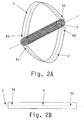
- the two ends 4a-4a' and 4b-4b', respectively, of the rotor blades 4-4' are according to the invention mounted on the horizontal shaft 3 with a spacing b between them; in a specific embodiment, the spacing b between the two ends 4a-4a' and 4b-4b', respectively, of the rotor blades 4-4' amounts to less than twice the radius R of each rotor blade 4-4'.
- said spacing b may amount to twice the radius R, and in yet another embodiment said spacing 2b may amount to more than twice the radius R of the rotor blade 4-4'. Twice the radius R of the rotor blade corresponds to the diameter D that the rotor blade describes in the air during operation.
- the two ends 4a-4a' and 4b-4b', respectively, of the rotor blades 4-4' are disposed near the first end 3a and the second end 3b, respectively, of the horizontal shaft 3.
- the rotor blades 4-4' are embodied as a thin, flat plate. More specifically, the plate-shaped rotor blades are furthermore flexible as regards its shape, so that they will automatically assume their desired shape, owing to the occurrence of centrifugal forces, during rotation of the horizontal shaft 3.
- Said shape also called chain line, ensures that only tensile stress will occur in the rotor blade and that consequently the stress at the two ends 3a and 3b, respectively, of the shaft 3 will be minimal, which enables a further simplification of the construction.
- FIGs. 3a and 3b show another embodiment of the invention.
- This embodiment makes use of rotor blades 4"-4"' of different shape, which rotor blades are likewise mounted on the horizontal shaft 3 with their first and second ends. More specifically, the rotor blades 4"-4"' are provided with additional wind capturing means 5, which preferably consist of a widened portion of the rotor blade 4"-4"'.
- the widened portion of the rotor blade which functions as a wind capturing means, is circular in shape; in the embodiment that is shown in Figs. 3a-3b , the widened portion of each rotor blade 4"-4"' functioning as a wind capturing means 5 is ellipsoidal in shape.
- the first main shaft 6 of the ellipsoidal wind capturing means 5 may thereby coincide with the longitudinal axis 7 of the rotor blade 4"; however, in order to obtain a strongly improved efficiency of the wind energy conversion apparatus, the first main shaft 6 includes an angle a with the longitudinal axis 7 of the rotor blade, which angle preferably ranges between 0° and 60°, more in particular between 20° and 40°.
- the widened portion 5 that functions as a wind capturing means does not form an ellipsoid in a geometric sense, but the ellipsoid 5 more or less smoothly merges with the outer circumference of the strip-shaped rotor or blade 4".
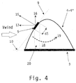
- any segment dS moves along the path described by the circumferential surface of a truncated cone, as is shown in Fig. 4 , wherein the plane of inflow 9 of the wind capturing means 5 intersects the horizontal shaft 3 at an upstream position 10, seen in the direction of the oncoming wind V wind .
- the wind reaction force 15 of the rotor 4" extends perpendicularly to the plane of inflow 9 of the wind capturing means 5. Said force 15 can be resolved into a force 17 acting in a direction parallel to the horizontal shaft 3 and a force 16 acting in the radial plane of the horizontal shaft 3.
- Said radial force 16 will create an underpressure in the region 18 surrounding the horizontal shaft 3, and furthermore said force 16 will carry air radially outwards downstream thereof, as is indicated by the arrow 19.
- the air flow will contract, causing the mass flow of the air through the entire apparatus and through the area of the rotors 4" to increase. This in turn results in more energy being drawn from the air flow, which leads to a significantly improved efficiency of such wind energy conversion apparatuses.
- the rotor blades according to the invention may be made of a metal or of a plastic material.
- the wind energy conversion apparatus according to the invention is characterized by a simple and light construction, which makes the wind energy conversion very suitable for use in areas not covered by the electricity grid.
- the wind energy conversion apparatuses Since only tensile stress, no flexural stress, occurs in the rotor blade, the wind energy conversion apparatuses is characterized by its light and simple construction. Since the aerodynamic angle of incidence of the wind V wind is furthermore constant (or at least not variable), and an actual rotor blade tip is missing, the wind energy conversion apparatus according to the invention is characterized by a very low noise level. This latter characteristic makes it possible to install the apparatus in built-up areas, whereas the noise level during operation of the wind energy conversion apparatuses that are currently known is generally too high to make installation thereof in built-up areas feasible.
Landscapes
- Engineering & Computer Science (AREA)
- Physics & Mathematics (AREA)
- Fluid Mechanics (AREA)
- Life Sciences & Earth Sciences (AREA)
- Sustainable Development (AREA)
- Sustainable Energy (AREA)
- Chemical & Material Sciences (AREA)
- Combustion & Propulsion (AREA)
- Mechanical Engineering (AREA)
- General Engineering & Computer Science (AREA)
- Wind Motors (AREA)
Claims (22)
- Windenergieumwandlungsvorrichtung, umfassend:eine Tragstruktur;eine horizontale Welle umfassend ein erstes und ein zweites Ende, die drehbar in der Tragstruktur gelagert ist,sowie mindestens ein streifenförmiges Rotorblatt umfassend ein erstes Ende und ein zweites Ende, wobei das Rotorblatt mit beiden Enden mit einer winkligen Verschiebung an der Welle angebracht ist, wobei das Rotorblatt in Gebrauch eine Querrippenform annimmt,
dadurch gekennzeichnet, dassdas Rotorblatt mit einem zusätzlichen Winderfassungsmittel versehen ist, umfassend einen verbreiterten Abschnitt aufweist, wobei der verbreiterte Abschnitt asymmetrisch entlang eines mittleren Abschnitts des Rotorblattes positioniert ist. - Windenergieumwandlungsvorrichtung gemäß Anspruch 1, dadurch gekennzeichnet, dass der verbreiterte Abschnitt eine Zustrom-Ebene umfasst, welche die horizontale Welle an einer vorgelagerten Position schneidet.
- Windenergieumwandlungsvorrichtung gemäß Anspruch 1 oder 2, dadurch gekennzeichnet, dass der verbreiterte Abschnitt kreisförmig ist.
- Windenergieumwandlungsvorrichtung gemäß Anspruch 1 oder 2, dadurch gekennzeichnet, dass der verbreiterte Abschnitt eine ellipsoide Form aufweist.
- Windenergieumwandlungsvorrichtung nach einem oder mehreren der vorhergehenden Ansprüche, dadurch gekennzeichnet, dass das Rotorblatt eine langgestreckte Form aufweist.
- Windenergieumwandlungsvorrichtung nach Anspruch 5, dadurch gekennzeichnet, dass das Rotorblatt eine flache, flexible Platte ist.
- Windenergieumwandlungsvorrichtung nach einem oder mehreren der vorhergehenden Ansprüche, dadurch gekennzeichnet, dass das Rotorblatt aus einem Metall hergestellt ist.
- Windenergieumwandlungsvorrichtung nach einem oder mehreren der vorhergehenden Ansprüche 1 bis 6, dadurch gekennzeichnet, dass das Rotorblatt aus einem Kunststoffmaterial hergestellt ist.
- Windenergieumwandlungsvorrichtung nach einem oder mehreren der vorhergehenden Ansprüche, dadurch gekennzeichnet, dass die Vorrichtung zwei oder mehr Rotorblätter, die auf der Welle montiert sind, umfasst.
- Windenergieumwandlungsvorrichtung nach Anspruch 9, dadurch gekennzeichnet, dass die Rotorblätter unterschiedliche Durchmesser im Betrieb beschreiben.
- Windenergieumwandlungsvorrichtung nach einem oder mehreren der vorhergehenden Ansprüche, dadurch gekennzeichnet, dass die Welle mit ihren beiden Enden in Lagern der Tragstruktur montiert ist.
- Windenergieumwandlungsvorrichtung nach einem oder mehreren der vorhergehenden Ansprüche, dadurch gekennzeichnet, dass die Welle mit einem Mittel, wie beispielsweise einem Generator, zum Umwandeln von Rotationsenergie in elektrische Energie verbunden ist.
- Windenergieumwandlungsvorrichtung nach einem oder mehreren der vorhergehenden Ansprüche, dadurch gekennzeichnet, dass der Generator in oder an der Lager-gelagerten Welle montiert ist.
- Windenergieumwandlungsvorrichtung nach einem oder mehreren der vorhergehenden Ansprüche, die ferner eine Mastkonstruktion umfasst, auf dem mindestens zwei Rotoren montiert sind.
- Rotorblatt zum Montieren an einer Windenergieumwandlungsvorrichtung montiert nach einem oder mehreren der vorhergehenden Ansprüche" wobei das Rotorblatt streifenförmig ist und ein erstes und ein zweites Ende aufweist, wobei das Rotorblatt mit seinen beiden Enden an einer drehbaren Welle der Windenergieumwandlungsvorrichtung montierbar ist, dadurch gekennzeichnet, dass das Rotorblatt mit einem zusätzlichen Winderfassungsmittel umfassend einen verbreiterten Abschnitt versehen ist, wobei der verbreiterte Abschnitt asymmetrisch entlang einem mittleren Abschnitt des Rotorblatt positioniert ist..
- Rotorblatt nach Anspruch 15, dadurch gekennzeichnet, dass der verbreiterte Abschnitt, wenn das Rotorblatt an der horizontalen Welle der Windenergieumwandlungsvorrichtung montiert ist, eine Zustrom-Ebene umfasst, welche die horizontale Welle an einer vorgelagerten Position schneidet.
- Rotorblatt nach Anspruch 15 oder 16, dadurch gekennzeichnet, dass der verbreiterte Abschnitt kreisförmig ist.
- Rotorblatt nach Anspruch 15 oder 16, dadurch gekennzeichnet, dass der verbreiterte Abschnitt eine elliptische Form aufweist.
- Rotorblatt nach einem oder mehreren der Ansprüche 15 bis 18, dadurch gekennzeichnet, dass das Rotorblatt eine langgestreckte Form aufweist.
- Rotorblatt nach Anspruch 19, dadurch gekennzeichnet, dass das Rotorblatt eine flache Platte ist.
- Rotorblatt nach einem oder mehreren der Ansprüche 15 bis 20, dadurch gekennzeichnet, dass das Rotorblatt aus einem Metall hergestellt ist.
- Rotorblatt nach einem oder mehreren der Ansprüche 15 bis 20, dadurch gekennzeichnet, dass das Rotorblatt aus einem Kunststoffmaterial hergestellt ist.
Applications Claiming Priority (3)
| Application Number | Priority Date | Filing Date | Title |
|---|---|---|---|
| NL1022393 | 2003-01-15 | ||
| NL1022393A NL1022393C2 (nl) | 2003-01-15 | 2003-01-15 | Windenergie-omzetinrichting alsmede een rotorblad voor toepassing in een dergelijke inrichting. |
| PCT/NL2004/000032 WO2004063564A1 (en) | 2003-01-15 | 2004-01-14 | A wind energy conversion apparatus |
Publications (2)
| Publication Number | Publication Date |
|---|---|
| EP1588049A1 EP1588049A1 (de) | 2005-10-26 |
| EP1588049B1 true EP1588049B1 (de) | 2016-10-26 |
Family
ID=32709988
Family Applications (1)
| Application Number | Title | Priority Date | Filing Date |
|---|---|---|---|
| EP04702097.9A Expired - Lifetime EP1588049B1 (de) | 2003-01-15 | 2004-01-14 | Windenergieumwandlungsvorrichtung |
Country Status (4)
| Country | Link |
|---|---|
| US (2) | US20060099077A1 (de) |
| EP (1) | EP1588049B1 (de) |
| NL (1) | NL1022393C2 (de) |
| WO (1) | WO2004063564A1 (de) |
Cited By (1)
| Publication number | Priority date | Publication date | Assignee | Title |
|---|---|---|---|---|
| DE102022110984A1 (de) | 2022-05-04 | 2022-06-30 | Otto Molerus | Windkraftanlage |
Families Citing this family (6)
| Publication number | Priority date | Publication date | Assignee | Title |
|---|---|---|---|---|
| DE10342113B4 (de) * | 2003-09-10 | 2009-08-20 | Fritz Kadletz | Windkraftmaschine |
| EP2128439A1 (de) | 2008-05-27 | 2009-12-02 | Syneola SA | Intelligentes dezentralisiertes elektrisches Stromerzeugungssystem |
| CN101684772A (zh) * | 2008-09-23 | 2010-03-31 | 张云龙 | 一种文丘里管效应的风力机转子 |
| WO2010037254A1 (zh) * | 2008-09-23 | 2010-04-08 | Zhang Yulong | 文丘里管效应的风力机转子 |
| US20110274558A1 (en) * | 2010-05-10 | 2011-11-10 | Kathryn Chase | Modular windmill |
| US8564148B1 (en) * | 2011-05-11 | 2013-10-22 | John J. Novak | AC energy generator |
Family Cites Families (15)
| Publication number | Priority date | Publication date | Assignee | Title |
|---|---|---|---|---|
| US527866A (en) * | 1894-10-23 | Windmill | ||
| FR627371A (fr) * | 1926-01-12 | 1927-10-03 | Inst Voor Aero En Hydro Dynami | Dispositif pour faciliter le démarrage de machines motrices à écoulement |
| FR646431A (fr) * | 1926-12-31 | 1928-11-12 | Propulseur rotatif flexible pour appareils de navigation aérienne | |
| US2020900A (en) * | 1934-01-18 | 1935-11-12 | Wilbur E Methvin | Stream motor |
| US3918839A (en) * | 1974-09-20 | 1975-11-11 | Us Energy | Wind turbine |
| US4012163A (en) * | 1975-09-08 | 1977-03-15 | Franklin W. Baumgartner | Wind driven power generator |
| JPS5770961A (en) | 1980-10-20 | 1982-05-01 | Hitachi Ltd | Vertical shaft driven windmill |
| DE3331166A1 (de) * | 1983-08-30 | 1985-03-14 | Erich Herter | Turbine |
| US4543042A (en) * | 1984-10-29 | 1985-09-24 | Heinz Lange | Windmill rotor |
| FR2609506B1 (fr) * | 1987-01-08 | 1993-05-28 | Lepoix Louis | Turbine multi-usage |
| DE3723101A1 (de) * | 1987-07-13 | 1989-02-16 | Manfred Uellenberg | Schrauben- oder rotorblatt fuer kraft- und arbeitsschraubenraeder und drehfluegelraeder |
| DE3919157A1 (de) * | 1988-06-11 | 1989-12-21 | Guenter Zillner | Windkraftmaschine |
| DE58903163D1 (de) * | 1988-10-03 | 1993-02-11 | Josef Moser | Windgetriebener rotor. |
| EP0716978B1 (de) * | 1994-12-16 | 2002-03-20 | Aldo Frediani | Grossraumflugzeug |
| DE19820766A1 (de) * | 1998-05-08 | 1999-11-11 | Genius Ingenieurgesellschaft M | Strömungskraftmaschine |
-
2003
- 2003-01-15 NL NL1022393A patent/NL1022393C2/nl not_active IP Right Cessation
-
2004
- 2004-01-14 EP EP04702097.9A patent/EP1588049B1/de not_active Expired - Lifetime
- 2004-01-14 WO PCT/NL2004/000032 patent/WO2004063564A1/en not_active Ceased
- 2004-01-14 US US10/542,428 patent/US20060099077A1/en not_active Abandoned
-
2009
- 2009-11-13 US US12/591,269 patent/US8105010B2/en not_active Expired - Fee Related
Cited By (2)
| Publication number | Priority date | Publication date | Assignee | Title |
|---|---|---|---|---|
| DE102022110984A1 (de) | 2022-05-04 | 2022-06-30 | Otto Molerus | Windkraftanlage |
| DE102022110984B4 (de) | 2022-05-04 | 2023-03-23 | Otto Molerus | Windkraftanlage |
Also Published As
| Publication number | Publication date |
|---|---|
| WO2004063564B1 (en) | 2004-09-10 |
| US8105010B2 (en) | 2012-01-31 |
| US20060099077A1 (en) | 2006-05-11 |
| US20100158692A1 (en) | 2010-06-24 |
| EP1588049A1 (de) | 2005-10-26 |
| WO2004063564A1 (en) | 2004-07-29 |
| NL1022393C2 (nl) | 2004-07-19 |
Similar Documents
| Publication | Publication Date | Title |
|---|---|---|
| US6641367B1 (en) | Wind energy conversion apparatus | |
| US8105010B2 (en) | Wind energy conversion apparatus | |
| CA2533426C (en) | Vertical-axis wind turbine | |
| US7976267B2 (en) | Helix turbine system and energy production means | |
| JP5785181B2 (ja) | タービン | |
| US20070166159A1 (en) | Wind turbine | |
| EP2018474A1 (de) | Windturbine und windkraftanlage | |
| US8562299B2 (en) | Blade for a device for generating energy from a fluid flow | |
| WO2003058061A1 (en) | A vertical axis turbine | |
| KR102471788B1 (ko) | 전기 발전기용 회전자 | |
| KR20190096151A (ko) | 수평축 풍력발전장치 | |
| RU2135823C1 (ru) | Ветродвигатель с лопастями "колокол" или "аякс" | |
| CN101668944A (zh) | 风车轮 | |
| US20150322919A1 (en) | Electricity Generating Wind Turbine | |
| JP5918983B2 (ja) | 風力発電装置 | |
| RU2309290C1 (ru) | Лопастная ветроэнергетическая установка | |
| US20120321454A1 (en) | Wind power generation apparatus | |
| US20260098515A1 (en) | Wind Turbine | |
| JP2000352373A (ja) | 風力発電装置 | |
| KR102133201B1 (ko) | 수평축 항력형 발전장치 | |
| RU2293211C1 (ru) | Ротор ветродвигателя | |
| KR20110042452A (ko) | 풍력 발전장치 | |
| CN119957419A (zh) | 一种用于垂直轴风机的帆式阻风传动装置 | |
| CN119825611A (zh) | 叶轮结构及发电装置 | |
| HK1156674B (en) | Blade for a device for generating energy from a fluid flow |
Legal Events
| Date | Code | Title | Description |
|---|---|---|---|
| PUAI | Public reference made under article 153(3) epc to a published international application that has entered the european phase |
Free format text: ORIGINAL CODE: 0009012 |
|
| 17P | Request for examination filed |
Effective date: 20050714 |
|
| AK | Designated contracting states |
Kind code of ref document: A1 Designated state(s): AT BE BG CH CY CZ DE DK EE ES FI FR GB GR HU IE IT LI LU MC NL PT RO SE SI SK TR |
|
| AX | Request for extension of the european patent |
Extension state: AL LT LV MK |
|
| DAX | Request for extension of the european patent (deleted) | ||
| RAP1 | Party data changed (applicant data changed or rights of an application transferred) |
Owner name: WIND EN WATER TECHNOLOGIE HOLDING B.V. |
|
| 17Q | First examination report despatched |
Effective date: 20110426 |
|
| GRAP | Despatch of communication of intention to grant a patent |
Free format text: ORIGINAL CODE: EPIDOSNIGR1 |
|
| INTG | Intention to grant announced |
Effective date: 20160503 |
|
| GRAS | Grant fee paid |
Free format text: ORIGINAL CODE: EPIDOSNIGR3 |
|
| GRAA | (expected) grant |
Free format text: ORIGINAL CODE: 0009210 |
|
| AK | Designated contracting states |
Kind code of ref document: B1 Designated state(s): AT BE BG CH CY CZ DE DK EE ES FI FR GB GR HU IE IT LI LU MC NL PT RO SE SI SK TR |
|
| REG | Reference to a national code |
Ref country code: GB Ref legal event code: FG4D |
|
| REG | Reference to a national code |
Ref country code: CH Ref legal event code: EP |
|
| REG | Reference to a national code |
Ref country code: AT Ref legal event code: REF Ref document number: 840215 Country of ref document: AT Kind code of ref document: T Effective date: 20161115 |
|
| REG | Reference to a national code |
Ref country code: IE Ref legal event code: FG4D |
|
| REG | Reference to a national code |
Ref country code: DE Ref legal event code: R096 Ref document number: 602004050181 Country of ref document: DE |
|
| REG | Reference to a national code |
Ref country code: NL Ref legal event code: FP |
|
| REG | Reference to a national code |
Ref country code: AT Ref legal event code: MK05 Ref document number: 840215 Country of ref document: AT Kind code of ref document: T Effective date: 20161026 |
|
| PG25 | Lapsed in a contracting state [announced via postgrant information from national office to epo] |
Ref country code: SE Free format text: LAPSE BECAUSE OF FAILURE TO SUBMIT A TRANSLATION OF THE DESCRIPTION OR TO PAY THE FEE WITHIN THE PRESCRIBED TIME-LIMIT Effective date: 20161026 Ref country code: GR Free format text: LAPSE BECAUSE OF FAILURE TO SUBMIT A TRANSLATION OF THE DESCRIPTION OR TO PAY THE FEE WITHIN THE PRESCRIBED TIME-LIMIT Effective date: 20170127 |
|
| PG25 | Lapsed in a contracting state [announced via postgrant information from national office to epo] |
Ref country code: ES Free format text: LAPSE BECAUSE OF FAILURE TO SUBMIT A TRANSLATION OF THE DESCRIPTION OR TO PAY THE FEE WITHIN THE PRESCRIBED TIME-LIMIT Effective date: 20161026 Ref country code: BE Free format text: LAPSE BECAUSE OF FAILURE TO SUBMIT A TRANSLATION OF THE DESCRIPTION OR TO PAY THE FEE WITHIN THE PRESCRIBED TIME-LIMIT Effective date: 20161026 Ref country code: AT Free format text: LAPSE BECAUSE OF FAILURE TO SUBMIT A TRANSLATION OF THE DESCRIPTION OR TO PAY THE FEE WITHIN THE PRESCRIBED TIME-LIMIT Effective date: 20161026 Ref country code: FI Free format text: LAPSE BECAUSE OF FAILURE TO SUBMIT A TRANSLATION OF THE DESCRIPTION OR TO PAY THE FEE WITHIN THE PRESCRIBED TIME-LIMIT Effective date: 20161026 Ref country code: PT Free format text: LAPSE BECAUSE OF FAILURE TO SUBMIT A TRANSLATION OF THE DESCRIPTION OR TO PAY THE FEE WITHIN THE PRESCRIBED TIME-LIMIT Effective date: 20170227 |
|
| REG | Reference to a national code |
Ref country code: DE Ref legal event code: R097 Ref document number: 602004050181 Country of ref document: DE |
|
| PG25 | Lapsed in a contracting state [announced via postgrant information from national office to epo] |
Ref country code: RO Free format text: LAPSE BECAUSE OF FAILURE TO SUBMIT A TRANSLATION OF THE DESCRIPTION OR TO PAY THE FEE WITHIN THE PRESCRIBED TIME-LIMIT Effective date: 20161026 Ref country code: CZ Free format text: LAPSE BECAUSE OF FAILURE TO SUBMIT A TRANSLATION OF THE DESCRIPTION OR TO PAY THE FEE WITHIN THE PRESCRIBED TIME-LIMIT Effective date: 20161026 Ref country code: EE Free format text: LAPSE BECAUSE OF FAILURE TO SUBMIT A TRANSLATION OF THE DESCRIPTION OR TO PAY THE FEE WITHIN THE PRESCRIBED TIME-LIMIT Effective date: 20161026 Ref country code: SK Free format text: LAPSE BECAUSE OF FAILURE TO SUBMIT A TRANSLATION OF THE DESCRIPTION OR TO PAY THE FEE WITHIN THE PRESCRIBED TIME-LIMIT Effective date: 20161026 Ref country code: DK Free format text: LAPSE BECAUSE OF FAILURE TO SUBMIT A TRANSLATION OF THE DESCRIPTION OR TO PAY THE FEE WITHIN THE PRESCRIBED TIME-LIMIT Effective date: 20161026 |
|
| PG25 | Lapsed in a contracting state [announced via postgrant information from national office to epo] |
Ref country code: IT Free format text: LAPSE BECAUSE OF FAILURE TO SUBMIT A TRANSLATION OF THE DESCRIPTION OR TO PAY THE FEE WITHIN THE PRESCRIBED TIME-LIMIT Effective date: 20161026 Ref country code: BG Free format text: LAPSE BECAUSE OF FAILURE TO SUBMIT A TRANSLATION OF THE DESCRIPTION OR TO PAY THE FEE WITHIN THE PRESCRIBED TIME-LIMIT Effective date: 20170126 |
|
| REG | Reference to a national code |
Ref country code: CH Ref legal event code: PL |
|
| PLBE | No opposition filed within time limit |
Free format text: ORIGINAL CODE: 0009261 |
|
| STAA | Information on the status of an ep patent application or granted ep patent |
Free format text: STATUS: NO OPPOSITION FILED WITHIN TIME LIMIT |
|
| REG | Reference to a national code |
Ref country code: NL Ref legal event code: MM Effective date: 20170201 |
|
| GBPC | Gb: european patent ceased through non-payment of renewal fee |
Effective date: 20170126 |
|
| PG25 | Lapsed in a contracting state [announced via postgrant information from national office to epo] |
Ref country code: MC Free format text: LAPSE BECAUSE OF FAILURE TO SUBMIT A TRANSLATION OF THE DESCRIPTION OR TO PAY THE FEE WITHIN THE PRESCRIBED TIME-LIMIT Effective date: 20161026 |
|
| 26N | No opposition filed |
Effective date: 20170727 |
|
| REG | Reference to a national code |
Ref country code: FR Ref legal event code: ST Effective date: 20170929 |
|
| PG25 | Lapsed in a contracting state [announced via postgrant information from national office to epo] |
Ref country code: CH Free format text: LAPSE BECAUSE OF NON-PAYMENT OF DUE FEES Effective date: 20170131 Ref country code: FR Free format text: LAPSE BECAUSE OF NON-PAYMENT OF DUE FEES Effective date: 20170131 Ref country code: LI Free format text: LAPSE BECAUSE OF NON-PAYMENT OF DUE FEES Effective date: 20170131 |
|
| PGFP | Annual fee paid to national office [announced via postgrant information from national office to epo] |
Ref country code: DE Payment date: 20170731 Year of fee payment: 14 |
|
| REG | Reference to a national code |
Ref country code: IE Ref legal event code: MM4A |
|
| PG25 | Lapsed in a contracting state [announced via postgrant information from national office to epo] |
Ref country code: LU Free format text: LAPSE BECAUSE OF NON-PAYMENT OF DUE FEES Effective date: 20170114 Ref country code: SI Free format text: LAPSE BECAUSE OF FAILURE TO SUBMIT A TRANSLATION OF THE DESCRIPTION OR TO PAY THE FEE WITHIN THE PRESCRIBED TIME-LIMIT Effective date: 20161026 Ref country code: NL Free format text: LAPSE BECAUSE OF NON-PAYMENT OF DUE FEES Effective date: 20170201 Ref country code: GB Free format text: LAPSE BECAUSE OF NON-PAYMENT OF DUE FEES Effective date: 20170126 |
|
| PG25 | Lapsed in a contracting state [announced via postgrant information from national office to epo] |
Ref country code: IE Free format text: LAPSE BECAUSE OF NON-PAYMENT OF DUE FEES Effective date: 20170114 |
|
| REG | Reference to a national code |
Ref country code: DE Ref legal event code: R119 Ref document number: 602004050181 Country of ref document: DE |
|
| PG25 | Lapsed in a contracting state [announced via postgrant information from national office to epo] |
Ref country code: DE Free format text: LAPSE BECAUSE OF NON-PAYMENT OF DUE FEES Effective date: 20180801 |
|
| PG25 | Lapsed in a contracting state [announced via postgrant information from national office to epo] |
Ref country code: HU Free format text: LAPSE BECAUSE OF FAILURE TO SUBMIT A TRANSLATION OF THE DESCRIPTION OR TO PAY THE FEE WITHIN THE PRESCRIBED TIME-LIMIT; INVALID AB INITIO Effective date: 20040114 |
|
| PG25 | Lapsed in a contracting state [announced via postgrant information from national office to epo] |
Ref country code: CY Free format text: LAPSE BECAUSE OF NON-PAYMENT OF DUE FEES Effective date: 20161026 |
|
| PG25 | Lapsed in a contracting state [announced via postgrant information from national office to epo] |
Ref country code: TR Free format text: LAPSE BECAUSE OF FAILURE TO SUBMIT A TRANSLATION OF THE DESCRIPTION OR TO PAY THE FEE WITHIN THE PRESCRIBED TIME-LIMIT Effective date: 20161026 |