EP1588094B1 - Tragbare beleuchtungsvorrichtung mit leuchtdioden - Google Patents
Tragbare beleuchtungsvorrichtung mit leuchtdioden Download PDFInfo
- Publication number
- EP1588094B1 EP1588094B1 EP04705836A EP04705836A EP1588094B1 EP 1588094 B1 EP1588094 B1 EP 1588094B1 EP 04705836 A EP04705836 A EP 04705836A EP 04705836 A EP04705836 A EP 04705836A EP 1588094 B1 EP1588094 B1 EP 1588094B1
- Authority
- EP
- European Patent Office
- Prior art keywords
- diode
- lighting lamp
- lamp according
- casing
- support
- Prior art date
- Legal status (The legal status is an assumption and is not a legal conclusion. Google has not performed a legal analysis and makes no representation as to the accuracy of the status listed.)
- Expired - Lifetime
Links
- 230000003287 optical effect Effects 0.000 claims abstract description 21
- 239000011521 glass Substances 0.000 claims description 7
- 238000012800 visualization Methods 0.000 claims description 2
- 238000005286 illumination Methods 0.000 description 7
- 230000004907 flux Effects 0.000 description 3
- 239000004417 polycarbonate Substances 0.000 description 2
- 229920000515 polycarbonate Polymers 0.000 description 2
- 230000005855 radiation Effects 0.000 description 2
- 239000004065 semiconductor Substances 0.000 description 2
- 208000036829 Device dislocation Diseases 0.000 description 1
- 239000012141 concentrate Substances 0.000 description 1
- 238000006073 displacement reaction Methods 0.000 description 1
- 239000003822 epoxy resin Substances 0.000 description 1
- 229920003023 plastic Polymers 0.000 description 1
- 229920000647 polyepoxide Polymers 0.000 description 1
- 230000001681 protective effect Effects 0.000 description 1
- 229920005989 resin Polymers 0.000 description 1
- 239000011347 resin Substances 0.000 description 1
- 239000000758 substrate Substances 0.000 description 1
Images



Classifications
-
- F—MECHANICAL ENGINEERING; LIGHTING; HEATING; WEAPONS; BLASTING
- F21—LIGHTING
- F21V—FUNCTIONAL FEATURES OR DETAILS OF LIGHTING DEVICES OR SYSTEMS THEREOF; STRUCTURAL COMBINATIONS OF LIGHTING DEVICES WITH OTHER ARTICLES, NOT OTHERWISE PROVIDED FOR
- F21V14/00—Controlling the distribution of the light emitted by adjustment of elements
- F21V14/06—Controlling the distribution of the light emitted by adjustment of elements by movement of refractors
- F21V14/065—Controlling the distribution of the light emitted by adjustment of elements by movement of refractors in portable lighting devices
-
- F—MECHANICAL ENGINEERING; LIGHTING; HEATING; WEAPONS; BLASTING
- F21—LIGHTING
- F21V—FUNCTIONAL FEATURES OR DETAILS OF LIGHTING DEVICES OR SYSTEMS THEREOF; STRUCTURAL COMBINATIONS OF LIGHTING DEVICES WITH OTHER ARTICLES, NOT OTHERWISE PROVIDED FOR
- F21V5/00—Refractors for light sources
- F21V5/04—Refractors for light sources of lens shape
- F21V5/045—Refractors for light sources of lens shape the lens having discontinuous faces, e.g. Fresnel lenses
-
- F—MECHANICAL ENGINEERING; LIGHTING; HEATING; WEAPONS; BLASTING
- F21—LIGHTING
- F21Y—INDEXING SCHEME ASSOCIATED WITH SUBCLASSES F21K, F21L, F21S and F21V, RELATING TO THE FORM OR THE KIND OF THE LIGHT SOURCES OR OF THE COLOUR OF THE LIGHT EMITTED
- F21Y2115/00—Light-generating elements of semiconductor light sources
- F21Y2115/10—Light-emitting diodes [LED]
Definitions
- An LED light emitting diode typically comprises a semiconductor component associated with a reflector within a transparent plastic casing, for example based on an epoxy resin.
- the front part of the molded envelope constitutes an internal lens or loupe, through which the light radiation produced by the light-emitting diode passes as a result of its connection to a power source.
- the viewing angle emitted by the diode depends on the shape of the reflector and the internal distance between the component and the lens. This viewing angle is constant for a type of LED, for example 20 °, and concentrates the majority of the useful luminous flux.
- an LED In order to vary the intensity of the luminous flux emitted by an LED, it is conventional to supply it via an adjustable current electronic circuit, for example a DC-DC converter, or a microcontroller connected to a battery. or batteries. This adjustment of the supply current causes a variation of the illumination power, but does not act on the radiation angle of the useful light beam.
- a conventional reflector of an incandescent lamp also does not allow to vary the viewing angle of an LED, because it acts in an area where the lamp emits very little light.
- the document US 6474837 relates to a light emitting diode lamp, according to the preamble of claim 1, and comprising a turntable in the form of a diaphragm pierced with orifices and provided with lenses placed in line with the orifices.
- the document WO 01/57431 discloses a lighting device consisting of an LED diode in front of which is permanently arranged a translational lens to change the relative distance from the diode.
- the object of the invention is to provide a portable LED diode lamp for easily adjusting the angle of the illuminating cone of said LED diode, to adjust the concentration of the luminous flux to obtain a wide range of illumination. short, or narrow and long-range lighting ..
- this object is achieved by the fact that the light-emitting diode of the emitter module is associated at the front with a magnifier housed in the orifice of the housing, and that the support of the lens is mounted on the outside of the housing. casing by coming in front of the magnifying glass in the active position.
- the lens holder can be mounted on a tilting or sliding plate, or on a rotary knob.
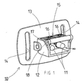
- a portable lighting device 10 comprises an emitter module ME equipped with at least one LED 11 for emitting a light beam, an element 12 for fixing and connecting said diode, and adjustment means of the light beam.
- the emitter module ME may consist of a single diode or a plurality of diodes 11 depending on the desired power rating.
- the element 12 of rectangular shape is secured to a base 13 equipped with a pair of slots 14 for receiving the fastening strap (not shown) of the headlamp.
- the adjustment means comprise an optical focusing device 15 that can be moved manually by the user in front of each LED.
- the illuminating cone can be obtained, either wide and short-range illumination, or narrow and long-range illumination.
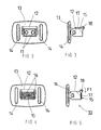
- the optical focusing device 15 advantageously comprises two Fresnel lenses 16 integral with a movable support 17 movable between an inactive position located outside the light emission field of the diodes 11 ( Figures 1 to 3 ), and an active position ( Figures 4 and 5 ) in which the lenses 16 are traversed by said light beam by undergoing a deviation of the viewing angle.
- the lenses 16 are carried by a folding plate of the support 17, which is pivotally mounted about a horizontal axis 18 arranged at the upper part of the base 13.
- the support plate 17 bears on the upper edge of the element 12, leaving the diodes 11 visible.
- the user folds the plate of the mobile support 17 in front of the front face of the device. lighting 10 (arrow F1, figure 5 ), forcing the light beam emitted by the diodes 11 to pass through the lenses 16. This then results in a variation of the viewing angle and the illumination cone, to obtain either a wide illumination and short range, or a lighting narrow and long reach.
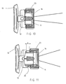
- the Figures 11A and 11B represent a Fresnel lens 11 used in the optical focusing device 15 of Figures 1 to 5 . It comprises a flat transparent substrate 19, made of polycarbonate or resin, in which are etched streaks 20 distributed in several concentric circular tracks 21 on one of the faces. The central portion 22 of the lens 11 is slightly curved and devoid of striations 20.
- the mobile support element 12 may comprise a plurality of lenses 16 corresponding to the same number of LEDs.
- the latter can be arranged in alignment, staggered, or angularly distributed at regular intervals around the periphery of the optical focusing device 15.
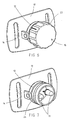
- the optical focusing device 15 instead of being mounted on a support 17 with folding plate, is fixed on a rotary knob 23 rotatable on a tip 24 of the support member 12 of circular shape.
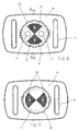
- the two lenses 16 are diametrically opposed, and the angular adjustment stroke of the button 23 between the inactive position ( figure 8 ) and the active position ( figure 9 ) corresponds to a quarter turn in the case of two LEDs.
- the distance d between the end of the button 23 and a stop 25 of the support member 12 can be changed during an axial movement movement of the focusing device. This results in a continuous adjustment of the angle of the lighting cone of the light beam following the relative movement of the lens 16 relative to the diode 11.
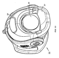
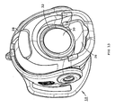
- a lamp L1 is provided with an emitter module ME with a single diode 11 mounted at the rear on a radiator 31 and associated at the front with a magnifying glass 30.
- a module Semiconductor emitter ME is a standard commercial component, housed inside the housing 28 and intended to emit a light beam through a circular orifice 32 of the housing.
- a plate 26 carries the optical focusing device 15, which may be made of integrated optics, for example polycarbonate or glass. The plate 26 is pivotally mounted about a horizontal axis located below the emitter module ME.
- the plate 26 In the active position ( figure 12 ), the plate 26 is placed in front of the magnifying glass 30, and is traversed by the beam emitted by the diode 11. In the inactive position ( figures 13 and 14 ), the plate 26 is lowered by bearing on a flange 27 fixed housing 28 to be protected.
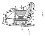
- a lamp L2 comprises a housing 28 of rectangular shape, having a housing compartment of the transmitter module ME, and a sliding drawer 33 integrating the optical focusing device 15.
- the drawer 33 is movable in translation in a vertical plane perpendicular to the light beam thanks to guide grooves 29 provided in the housing 28.
- the slide 33 is protected by a removable cap 34 which can be plugged into the housing 28.
- a gripping pin 35 moves the slide 33 between the retracted position ( figures 19 ) and the apparent position ( figure 18 ).
- the cap 34 may remain in place during this setting operation.
- the drawer 33 constitutes a one-piece piece having a predetermined focal length. This piece is easily interchangeable after removal of the cap 34.
Landscapes
- Engineering & Computer Science (AREA)
- General Engineering & Computer Science (AREA)
- Securing Globes, Refractors, Reflectors Or The Like (AREA)
- Led Device Packages (AREA)
- Fastening Of Light Sources Or Lamp Holders (AREA)
- Led Devices (AREA)
- Non-Portable Lighting Devices Or Systems Thereof (AREA)
Claims (9)
- Tragbare Lampe (10), die umfasst:- ein mit einer Öffnung (32) versehenes Gehäuse (28),- einem Emissionsmodul (ME), das mit einer Licht emittierenden Diode (11) zum Aussenden eines Lichtstrahls durch die Öffnung (32) hindurch versehen ist,- ein Element (12) zur Befestigung und zum Anschluss der Diode,- und Mittel zur Regulierung des Lichtstrahls, die eine optische Fokussierungseinrichtung (15) umfassen, die von mindestens einer Linse gebildet wird, die auf einem transparenten Träger (26, 33) angeordnet ist und mit diesem einstückig verbunden ist, welcher Träger zur Variierung des Ausleuchtwinkels des Lichtstrahls manuell zwischen einer inaktiven Position, die außerhalb des Licht-Ausstrahlungsfelds der Diode (11) liegt, und einer aktiven Position gegenüber der Diode (11) beweglich ist,dadurch gekennzeichnet, dass die Licht emittierende Diode (11) des Emissionsmoduls (ME) vorne mit einer Lupe (30) verbunden ist, die in der Öffnung (32) des Gehäuses (28) angeordnet ist, und dass der Träger (26, 33) der Linse außerhalb des Gehäuses (28) montiert ist und sich in aktiver Position vor der Lupe (30) befindet.
- Lampe nach Anspruch 1, dadurch gekennzeichnet, dass die Linse (16) eine Fresnel-Linse ist.
- Lampe nach Anspruch 1, dadurch gekennzeichnet, dass der bewegliche Träger (26, 33) bistabil ist, um einen breiten Lichtstrahl mit kurzer Reichweite oder einen schmalen Lichtstrahl mit langer Reichweite zu erzeugen.
- Lampe nach Anspruch 1, dadurch gekennzeichnet, dass der bewegliche Träger (26) der optischen Fokussierungseinrichtung (15) von einer kippbaren Platte gebildet wird, die schwenkbar um eine Achse (18) montiert ist, die sich bezüglich der Diode (11) orthogonal erstreckt.
- Lampe nach Anspruch 4, dadurch gekennzeichnet, dass die Trägerplatte (26) in inaktiver Position auf einem festen erhöhten Rand (27) außerhalb des Gehäuses (28) aufliegt.
- Lampe nach Anspruch 1, dadurch gekennzeichnet, dass der bewegliche Träger (33) der optischen Fokussierungseinrichtung (15) von einem Einschub (33) gebildet wird, der in Rillen (29) des Gehäuses (28) gleitend montiert ist, um sich in aktiver Position vor der Lupe (30) zu positionieren.
- Lampe nach Anspruch 6, dadurch gekennzeichnet, dass der Einschub (33) der optischen Fokussierungseinrichtung (15) von einem austauschbaren Element mit vorbestimmtem Fokalabstand gebildet wird.
- Lampe nach Anspruch 6 oder 7, dadurch gekennzeichnet, dass der Einschub (33) durch einen abnehmbaren Deckel (34) geschützt ist, der in das Gehäuse (28) eingeschoben werden kann und das Gleiten des Einschubs (33) zwischen der eingezogenen und der sichtbaren Position ermöglicht.
- Lampe nach Anspruch 1, dadurch gekennzeichnet, dass die Licht emittierende Diode (11) hinten mit einem Wärmeableiter (31) verbunden ist, der in dem Gehäuse (28) angeordnet ist.
Applications Claiming Priority (3)
| Application Number | Priority Date | Filing Date | Title |
|---|---|---|---|
| FR0300980A FR2850448B1 (fr) | 2003-01-29 | 2003-01-29 | Dispositif d'eclairage portatif a diode electroluninescente |
| FR0300980 | 2003-01-29 | ||
| PCT/FR2004/000199 WO2004070268A2 (fr) | 2003-01-29 | 2004-01-28 | Dispositif d’eclairage portatif a diode electroluminescente |
Publications (2)
| Publication Number | Publication Date |
|---|---|
| EP1588094A2 EP1588094A2 (de) | 2005-10-26 |
| EP1588094B1 true EP1588094B1 (de) | 2008-03-12 |
Family
ID=32669304
Family Applications (1)
| Application Number | Title | Priority Date | Filing Date |
|---|---|---|---|
| EP04705836A Expired - Lifetime EP1588094B1 (de) | 2003-01-29 | 2004-01-28 | Tragbare beleuchtungsvorrichtung mit leuchtdioden |
Country Status (7)
| Country | Link |
|---|---|
| US (2) | US7192165B2 (de) |
| EP (1) | EP1588094B1 (de) |
| CN (1) | CN100529521C (de) |
| AT (1) | ATE389146T1 (de) |
| DE (1) | DE602004012389T2 (de) |
| FR (1) | FR2850448B1 (de) |
| WO (1) | WO2004070268A2 (de) |
Cited By (3)
| Publication number | Priority date | Publication date | Assignee | Title |
|---|---|---|---|---|
| USD729426S1 (en) | 2013-01-10 | 2015-05-12 | Streamlight, Inc. | Mountable light |
| USD733951S1 (en) | 2012-11-21 | 2015-07-07 | Streamlight, Inc. | Wearable portable light |
| USD750823S1 (en) | 2012-05-10 | 2016-03-01 | Streamlight, Inc. | Mountable light |
Families Citing this family (24)
| Publication number | Priority date | Publication date | Assignee | Title |
|---|---|---|---|---|
| FR2850448B1 (fr) * | 2003-01-29 | 2006-01-20 | Zedel | Dispositif d'eclairage portatif a diode electroluninescente |
| DE602004014951D1 (de) * | 2004-12-07 | 2008-08-21 | Cariboni Lite S R L | Lampe mit Dioden |
| EP1754933A1 (de) * | 2005-08-18 | 2007-02-21 | Eltam Ein Hashofet | Leuchte für militärischen Gebrauch |
| US7377665B2 (en) * | 2006-01-20 | 2008-05-27 | Keith Allan Langenwalter | Buckle-mounted light |
| FR2896853B1 (fr) * | 2006-01-27 | 2008-05-16 | Zedel Soc Par Actions Simplifi | Lampe d'eclairage electrique equipee d'un dispositif de fixation et de positionnement sur un support. |
| US8147083B2 (en) * | 2007-01-12 | 2012-04-03 | Underwater Kinetics, Inc. | Headlights having adjustable intensity |
| AU2008207968B2 (en) * | 2007-01-23 | 2013-08-29 | Energizer Brands, Llc | Headlamp with adjustable diffuser lens |
| GB0914933D0 (en) | 2009-08-27 | 2009-09-30 | Ritelite Systems Ltd | A portable lighting device |
| US10234105B2 (en) | 2009-09-12 | 2019-03-19 | Robe Lighting S.R.O. | Optics for an automated luminaire |
| WO2011032057A1 (en) * | 2009-09-12 | 2011-03-17 | Robe Lighting Inc | Improved optics for an automated luminaire |
| FR2988160B1 (fr) * | 2012-03-14 | 2014-03-28 | Zedel | Lampe electrique portative a boitier compact monte angulairement deplacable |
| CH706356A1 (de) * | 2012-04-15 | 2013-10-15 | Belux Ip Ag | Vorrichtung zur Einstellung des Austrittswinkels des Lichts an einer elektrischen Leuchte. |
| US9285105B2 (en) | 2012-05-08 | 2016-03-15 | Streamlight, Inc. | Head light having a rotatable face cap with plural lenses |
| US9470382B1 (en) | 2013-04-24 | 2016-10-18 | Streamlight, Inc. | Portable light |
| US9249964B2 (en) * | 2014-01-08 | 2016-02-02 | Zweibruder Optoelectronics Gmbh & Co. Kg | Multi-purpose illumination device |
| US9140431B1 (en) * | 2014-03-05 | 2015-09-22 | Wen-Sung Lee | Lighting device with adjusting mechanism |
| US10030847B2 (en) | 2014-03-10 | 2018-07-24 | Streamlight, Inc. | Portable light and optical diffuser therefor |
| US9909744B2 (en) * | 2015-01-05 | 2018-03-06 | Industrial Revolution, Inc. | Portable lighting devices with multiuse lanyards and detachable lanyards |
| DE202016100958U1 (de) * | 2016-02-24 | 2017-05-26 | Zumtobel Lighting Gmbh | Beleuchtungsanordnung mit zumindest zwei optischen Elementen |
| CN110748816A (zh) * | 2018-07-24 | 2020-02-04 | 东莞市欧微照明科技有限公司 | 一种实现光学模式切换的牙科灯和手术照明灯两用装置 |
| US20200109916A1 (en) | 2018-10-09 | 2020-04-09 | Streamlight, Inc. | Rail mountable gun light with aiming light and rotationally keyed mount assembly |
| CA3205354A1 (en) | 2020-05-09 | 2021-11-18 | Ideapond Llc | Broad view headlamp |
| US11639789B2 (en) | 2021-01-13 | 2023-05-02 | Streamlight, Inc. | Portable light and keyed rechargeable USB battery |
| USD1061974S1 (en) | 2021-08-03 | 2025-02-11 | Streamlight, Inc. | Portable light |
Family Cites Families (9)
| Publication number | Priority date | Publication date | Assignee | Title |
|---|---|---|---|---|
| DE283441C (de) * | 1900-01-01 | |||
| US3705983A (en) * | 1969-05-10 | 1972-12-12 | Naojiro Yamada | Flashlight |
| DE3379237D1 (en) * | 1982-12-04 | 1989-03-30 | Sassmannshausen Knut | Portable lamp |
| DE8515726U1 (de) | 1985-05-29 | 1985-07-18 | Lambertz, Christoph, Dr.med., 5242 Kirchen | Gerät zur Erzeugung von farbigem polarisiertem Licht |
| GB2264164B (en) * | 1992-02-06 | 1995-05-24 | Richard Stevens | Lamp |
| FR2745627A1 (fr) * | 1996-03-04 | 1997-09-05 | Grimaud Jacques | Lampe equipee d'un miroir mobile |
| DE10004019A1 (de) * | 2000-01-31 | 2001-08-02 | Guenther Bebenroth | Beleuchtungsvorrichtung zum Anstrahlen von Gegenständen oder Gebäuden |
| US6474837B1 (en) * | 2000-11-20 | 2002-11-05 | Richard S. Belliveau | Lighting device with beam altering mechanism incorporating a plurality of light souces |
| FR2850448B1 (fr) * | 2003-01-29 | 2006-01-20 | Zedel | Dispositif d'eclairage portatif a diode electroluninescente |
-
2003
- 2003-01-29 FR FR0300980A patent/FR2850448B1/fr not_active Expired - Fee Related
-
2004
- 2004-01-28 WO PCT/FR2004/000199 patent/WO2004070268A2/fr not_active Ceased
- 2004-01-28 US US10/532,812 patent/US7192165B2/en not_active Expired - Fee Related
- 2004-01-28 AT AT04705836T patent/ATE389146T1/de not_active IP Right Cessation
- 2004-01-28 EP EP04705836A patent/EP1588094B1/de not_active Expired - Lifetime
- 2004-01-28 CN CNB2004800012747A patent/CN100529521C/zh not_active Expired - Fee Related
- 2004-01-28 DE DE602004012389T patent/DE602004012389T2/de not_active Expired - Lifetime
-
2006
- 2006-12-13 US US11/637,902 patent/US7226190B2/en not_active Expired - Fee Related
Cited By (3)
| Publication number | Priority date | Publication date | Assignee | Title |
|---|---|---|---|---|
| USD750823S1 (en) | 2012-05-10 | 2016-03-01 | Streamlight, Inc. | Mountable light |
| USD733951S1 (en) | 2012-11-21 | 2015-07-07 | Streamlight, Inc. | Wearable portable light |
| USD729426S1 (en) | 2013-01-10 | 2015-05-12 | Streamlight, Inc. | Mountable light |
Also Published As
| Publication number | Publication date |
|---|---|
| WO2004070268A3 (fr) | 2004-09-16 |
| FR2850448B1 (fr) | 2006-01-20 |
| CN1705848A (zh) | 2005-12-07 |
| US20070097674A1 (en) | 2007-05-03 |
| WO2004070268A2 (fr) | 2004-08-19 |
| FR2850448A1 (fr) | 2004-07-30 |
| CN100529521C (zh) | 2009-08-19 |
| DE602004012389D1 (de) | 2008-04-24 |
| DE602004012389T2 (de) | 2009-04-23 |
| US7226190B2 (en) | 2007-06-05 |
| US7192165B2 (en) | 2007-03-20 |
| EP1588094A2 (de) | 2005-10-26 |
| US20060056175A1 (en) | 2006-03-16 |
| ATE389146T1 (de) | 2008-03-15 |
Similar Documents
| Publication | Publication Date | Title |
|---|---|---|
| WO2004070268A2 (fr) | Dispositif d’eclairage portatif a diode electroluminescente | |
| CA2810385C (fr) | Module optique de dispositif d'eclairage et/ou de signalisation d'un vehicule automobile | |
| EP2598797B1 (de) | Optisches modul einer beleuchtungs- und/oder signalisierungsvorrichtung eines kraftfahrzeuges | |
| FR3050253A1 (fr) | Feu de vehicule et vehicule comportant celui-ci | |
| WO1994012852A1 (fr) | Laser d'arpentage | |
| EP3537040B1 (de) | Leuchtmodul und leuchtvorrichtung für kraftfahrzeug, das ein solches leuchtmodul umfasst | |
| FR3086870A1 (fr) | Accessoire de type sabre laser | |
| WO2016050624A1 (fr) | Dispositif lumineux de vehicule avec des moyens de positionnement d'une carte electronique | |
| EP2295850A1 (de) | Vorrichtung zur Beleuchtung und/oder Signalisierung für Kraftfahrzeug | |
| FR3032514A1 (fr) | Module lumineux d’un vehicule compatible au trafic gauche et au trafic droit | |
| EP1739346B1 (de) | Nebelscheinwerfervorrichtung mit Projektionslinse | |
| EP3507543A1 (de) | Medizinische beleuchtungsvorrichtung mit leds, die durch in einer leiterplatte vorgeschnittene laschen ausgerichtet sind | |
| WO2023031072A1 (fr) | Module d'émission de lumière comprenant un support destiné à dissiper de la chaleur | |
| EP3190335B1 (de) | Leuchtvorrichtung, die mit einem gekrümmten umwandlungselement der wellenlänge ausgestattet ist, und scheinwerfer, der eine solche leuchtvorrichtung umfasst | |
| FR3088986A1 (fr) | Module lumineux multifonctions doté de deux guides de lumière de type plat | |
| EP3486554B1 (de) | Lichtmodul für fahrzeugscheinwerfer | |
| EP2926049B1 (de) | Fahrzeugsignalisierungsvorrichtung mit dreidimensionaler wirkung | |
| EP0736415B1 (de) | Beleuchtungseinrichtung für Anzeigeinstrumente in einem Armaturenbrett | |
| EP1590602A1 (de) | Beleuchtungsvorrichtung | |
| EP3628914B1 (de) | Optische bifunktionseinheit zum anzeigen und beleuchten | |
| FR3062458A1 (fr) | Module de projection d'un faisceau lumineux pour dispositif d'emission lumineuse de vehicule automobile | |
| CH648132A5 (fr) | Dispositif accessoire pour appareil de prises de vues. | |
| FR3015006A1 (fr) | Luminaire a photometrie ajustable |
Legal Events
| Date | Code | Title | Description |
|---|---|---|---|
| PUAI | Public reference made under article 153(3) epc to a published international application that has entered the european phase |
Free format text: ORIGINAL CODE: 0009012 |
|
| 17P | Request for examination filed |
Effective date: 20050330 |
|
| AK | Designated contracting states |
Kind code of ref document: A2 Designated state(s): AT BE BG CH CY CZ DE DK EE ES FI FR GB GR HU IE IT LI LU MC NL PT RO SE SI SK TR |
|
| AX | Request for extension of the european patent |
Extension state: AL LT LV MK |
|
| DAX | Request for extension of the european patent (deleted) | ||
| 17Q | First examination report despatched |
Effective date: 20070228 |
|
| 17Q | First examination report despatched |
Effective date: 20070228 |
|
| GRAP | Despatch of communication of intention to grant a patent |
Free format text: ORIGINAL CODE: EPIDOSNIGR1 |
|
| GRAS | Grant fee paid |
Free format text: ORIGINAL CODE: EPIDOSNIGR3 |
|
| GRAA | (expected) grant |
Free format text: ORIGINAL CODE: 0009210 |
|
| AK | Designated contracting states |
Kind code of ref document: B1 Designated state(s): AT BE BG CH CY CZ DE DK EE ES FI FR GB GR HU IE IT LI LU MC NL PT RO SE SI SK TR |
|
| REG | Reference to a national code |
Ref country code: GB Ref legal event code: FG4D Free format text: NOT ENGLISH |
|
| REG | Reference to a national code |
Ref country code: CH Ref legal event code: EP |
|
| REG | Reference to a national code |
Ref country code: IE Ref legal event code: FG4D Free format text: LANGUAGE OF EP DOCUMENT: FRENCH |
|
| REF | Corresponds to: |
Ref document number: 602004012389 Country of ref document: DE Date of ref document: 20080424 Kind code of ref document: P |
|
| REG | Reference to a national code |
Ref country code: SE Ref legal event code: TRGR |
|
| PG25 | Lapsed in a contracting state [announced via postgrant information from national office to epo] |
Ref country code: FI Free format text: LAPSE BECAUSE OF FAILURE TO SUBMIT A TRANSLATION OF THE DESCRIPTION OR TO PAY THE FEE WITHIN THE PRESCRIBED TIME-LIMIT Effective date: 20080312 |
|
| PG25 | Lapsed in a contracting state [announced via postgrant information from national office to epo] |
Ref country code: AT Free format text: LAPSE BECAUSE OF FAILURE TO SUBMIT A TRANSLATION OF THE DESCRIPTION OR TO PAY THE FEE WITHIN THE PRESCRIBED TIME-LIMIT Effective date: 20080312 |
|
| NLV1 | Nl: lapsed or annulled due to failure to fulfill the requirements of art. 29p and 29m of the patents act | ||
| PG25 | Lapsed in a contracting state [announced via postgrant information from national office to epo] |
Ref country code: SI Free format text: LAPSE BECAUSE OF FAILURE TO SUBMIT A TRANSLATION OF THE DESCRIPTION OR TO PAY THE FEE WITHIN THE PRESCRIBED TIME-LIMIT Effective date: 20080312 |
|
| REG | Reference to a national code |
Ref country code: IE Ref legal event code: FD4D |
|
| PG25 | Lapsed in a contracting state [announced via postgrant information from national office to epo] |
Ref country code: CZ Free format text: LAPSE BECAUSE OF FAILURE TO SUBMIT A TRANSLATION OF THE DESCRIPTION OR TO PAY THE FEE WITHIN THE PRESCRIBED TIME-LIMIT Effective date: 20080312 Ref country code: SK Free format text: LAPSE BECAUSE OF FAILURE TO SUBMIT A TRANSLATION OF THE DESCRIPTION OR TO PAY THE FEE WITHIN THE PRESCRIBED TIME-LIMIT Effective date: 20080312 Ref country code: PT Free format text: LAPSE BECAUSE OF FAILURE TO SUBMIT A TRANSLATION OF THE DESCRIPTION OR TO PAY THE FEE WITHIN THE PRESCRIBED TIME-LIMIT Effective date: 20080818 Ref country code: ES Free format text: LAPSE BECAUSE OF FAILURE TO SUBMIT A TRANSLATION OF THE DESCRIPTION OR TO PAY THE FEE WITHIN THE PRESCRIBED TIME-LIMIT Effective date: 20080623 |
|
| PG25 | Lapsed in a contracting state [announced via postgrant information from national office to epo] |
Ref country code: RO Free format text: LAPSE BECAUSE OF FAILURE TO SUBMIT A TRANSLATION OF THE DESCRIPTION OR TO PAY THE FEE WITHIN THE PRESCRIBED TIME-LIMIT Effective date: 20080312 Ref country code: NL Free format text: LAPSE BECAUSE OF FAILURE TO SUBMIT A TRANSLATION OF THE DESCRIPTION OR TO PAY THE FEE WITHIN THE PRESCRIBED TIME-LIMIT Effective date: 20080312 |
|
| PLBE | No opposition filed within time limit |
Free format text: ORIGINAL CODE: 0009261 |
|
| STAA | Information on the status of an ep patent application or granted ep patent |
Free format text: STATUS: NO OPPOSITION FILED WITHIN TIME LIMIT |
|
| PG25 | Lapsed in a contracting state [announced via postgrant information from national office to epo] |
Ref country code: DK Free format text: LAPSE BECAUSE OF FAILURE TO SUBMIT A TRANSLATION OF THE DESCRIPTION OR TO PAY THE FEE WITHIN THE PRESCRIBED TIME-LIMIT Effective date: 20080312 Ref country code: IE Free format text: LAPSE BECAUSE OF FAILURE TO SUBMIT A TRANSLATION OF THE DESCRIPTION OR TO PAY THE FEE WITHIN THE PRESCRIBED TIME-LIMIT Effective date: 20080312 |
|
| 26N | No opposition filed |
Effective date: 20081215 |
|
| PG25 | Lapsed in a contracting state [announced via postgrant information from national office to epo] |
Ref country code: EE Free format text: LAPSE BECAUSE OF FAILURE TO SUBMIT A TRANSLATION OF THE DESCRIPTION OR TO PAY THE FEE WITHIN THE PRESCRIBED TIME-LIMIT Effective date: 20080312 Ref country code: BG Free format text: LAPSE BECAUSE OF FAILURE TO SUBMIT A TRANSLATION OF THE DESCRIPTION OR TO PAY THE FEE WITHIN THE PRESCRIBED TIME-LIMIT Effective date: 20080612 |
|
| PG25 | Lapsed in a contracting state [announced via postgrant information from national office to epo] |
Ref country code: MC Free format text: LAPSE BECAUSE OF NON-PAYMENT OF DUE FEES Effective date: 20090131 |
|
| REG | Reference to a national code |
Ref country code: CH Ref legal event code: PL |
|
| PG25 | Lapsed in a contracting state [announced via postgrant information from national office to epo] |
Ref country code: CY Free format text: LAPSE BECAUSE OF FAILURE TO SUBMIT A TRANSLATION OF THE DESCRIPTION OR TO PAY THE FEE WITHIN THE PRESCRIBED TIME-LIMIT Effective date: 20080312 |
|
| PG25 | Lapsed in a contracting state [announced via postgrant information from national office to epo] |
Ref country code: LI Free format text: LAPSE BECAUSE OF NON-PAYMENT OF DUE FEES Effective date: 20090131 Ref country code: CH Free format text: LAPSE BECAUSE OF NON-PAYMENT OF DUE FEES Effective date: 20090131 |
|
| PG25 | Lapsed in a contracting state [announced via postgrant information from national office to epo] |
Ref country code: BE Free format text: LAPSE BECAUSE OF NON-PAYMENT OF DUE FEES Effective date: 20090131 |
|
| PG25 | Lapsed in a contracting state [announced via postgrant information from national office to epo] |
Ref country code: GR Free format text: LAPSE BECAUSE OF FAILURE TO SUBMIT A TRANSLATION OF THE DESCRIPTION OR TO PAY THE FEE WITHIN THE PRESCRIBED TIME-LIMIT Effective date: 20080613 |
|
| PG25 | Lapsed in a contracting state [announced via postgrant information from national office to epo] |
Ref country code: LU Free format text: LAPSE BECAUSE OF NON-PAYMENT OF DUE FEES Effective date: 20090128 |
|
| PG25 | Lapsed in a contracting state [announced via postgrant information from national office to epo] |
Ref country code: HU Free format text: LAPSE BECAUSE OF FAILURE TO SUBMIT A TRANSLATION OF THE DESCRIPTION OR TO PAY THE FEE WITHIN THE PRESCRIBED TIME-LIMIT Effective date: 20080913 |
|
| PG25 | Lapsed in a contracting state [announced via postgrant information from national office to epo] |
Ref country code: TR Free format text: LAPSE BECAUSE OF FAILURE TO SUBMIT A TRANSLATION OF THE DESCRIPTION OR TO PAY THE FEE WITHIN THE PRESCRIBED TIME-LIMIT Effective date: 20080312 |
|
| REG | Reference to a national code |
Ref country code: FR Ref legal event code: PLFP Year of fee payment: 13 |
|
| PGFP | Annual fee paid to national office [announced via postgrant information from national office to epo] |
Ref country code: FR Payment date: 20151208 Year of fee payment: 13 |
|
| PGFP | Annual fee paid to national office [announced via postgrant information from national office to epo] |
Ref country code: IT Payment date: 20160127 Year of fee payment: 13 Ref country code: DE Payment date: 20160119 Year of fee payment: 13 |
|
| PGFP | Annual fee paid to national office [announced via postgrant information from national office to epo] |
Ref country code: SE Payment date: 20160112 Year of fee payment: 13 Ref country code: GB Payment date: 20160127 Year of fee payment: 13 |
|
| REG | Reference to a national code |
Ref country code: DE Ref legal event code: R119 Ref document number: 602004012389 Country of ref document: DE |
|
| GBPC | Gb: european patent ceased through non-payment of renewal fee |
Effective date: 20170128 |
|
| REG | Reference to a national code |
Ref country code: FR Ref legal event code: ST Effective date: 20170929 |
|
| PG25 | Lapsed in a contracting state [announced via postgrant information from national office to epo] |
Ref country code: FR Free format text: LAPSE BECAUSE OF NON-PAYMENT OF DUE FEES Effective date: 20170131 |
|
| PG25 | Lapsed in a contracting state [announced via postgrant information from national office to epo] |
Ref country code: DE Free format text: LAPSE BECAUSE OF NON-PAYMENT OF DUE FEES Effective date: 20170801 Ref country code: SE Free format text: LAPSE BECAUSE OF NON-PAYMENT OF DUE FEES Effective date: 20170129 Ref country code: GB Free format text: LAPSE BECAUSE OF NON-PAYMENT OF DUE FEES Effective date: 20170128 |
|
| PG25 | Lapsed in a contracting state [announced via postgrant information from national office to epo] |
Ref country code: IT Free format text: LAPSE BECAUSE OF NON-PAYMENT OF DUE FEES Effective date: 20170128 |