EP1588585B1 - Elektrischer strahlungsheizer - Google Patents
Elektrischer strahlungsheizer Download PDFInfo
- Publication number
- EP1588585B1 EP1588585B1 EP04702740A EP04702740A EP1588585B1 EP 1588585 B1 EP1588585 B1 EP 1588585B1 EP 04702740 A EP04702740 A EP 04702740A EP 04702740 A EP04702740 A EP 04702740A EP 1588585 B1 EP1588585 B1 EP 1588585B1
- Authority
- EP
- European Patent Office
- Prior art keywords
- heater
- temperature
- responsive device
- rod
- heating element
- Prior art date
- Legal status (The legal status is an assumption and is not a legal conclusion. Google has not performed a legal analysis and makes no representation as to the accuracy of the status listed.)
- Expired - Lifetime
Links
Images

Classifications
-
- H—ELECTRICITY
- H05—ELECTRIC TECHNIQUES NOT OTHERWISE PROVIDED FOR
- H05B—ELECTRIC HEATING; ELECTRIC LIGHT SOURCES NOT OTHERWISE PROVIDED FOR; CIRCUIT ARRANGEMENTS FOR ELECTRIC LIGHT SOURCES, IN GENERAL
- H05B3/00—Ohmic-resistance heating
- H05B3/68—Heating arrangements specially adapted for cooking plates or analogous hot-plates
- H05B3/74—Non-metallic plates, e.g. vitroceramic, ceramic or glassceramic hobs, also including power or control circuits
- H05B3/748—Resistive heating elements, i.e. heating elements exposed to the air, e.g. coil wire heater
Definitions
- Radiant electric heaters are well known for use behind glass-ceramic cooking surfaces.
- Such heaters can comprise a dish-like support having therein a base layer of insulation material, such as microporous thermal and electrical insulation material.
- At least one electric heating element is provided, supported on the surface of the base layer.
- One form of heating element which has found wide acceptance is an elongate electrically conductive ribbon which is supported on edge and secured in the surface of the base layer.
- the rod-like temperature-responsive device when mounted on the heater may not be parallel to the base of the heater and such that the free end of the device is closer to the heating element than is the opposite end of the device.
- a local increase in temperature may occur in those regions of the heating element or elements which lie directly beneath the rod-like temperature-responsive device. This can result in premature operation of the temperature-responsive device and may also contribute to premature failure of the heating element or elements.
- This problem has been addressed in GB-A-2340715 wherein the surface of the base of thermal insulation material supporting the heating element or elements is provided with a shallow recess beneath the rod-like temperature-responsive device.
- a ribbon-form heating element, which is partially embedded in the base, is partially embedded to a lesser extent in the shallow recess than in the surface of the base at either side of the recess.
- EP-A-0 948 238 describes a radiant electric heater having a base of thermal and electrical insulation material, at least one heating element, and a rod-like temperature-responsive device extending partly across the heater.
- the base has a substantially continuous concave profile.
- EP-A-0 081 073 describes a radiant electric heater with a base of thermal and/or electrical insulation, a heating element and a heat sensor projecting at least partly over the heating element.
- the heat sensor passes in the vicinity of a portion of insulation which is hollowed out in trough-like manner.
- a radiant electric heater comprising:
- the rod-like temperature-responsive device may comprise metal and may comprise a metal tube.
- the rod-like temperature-responsive device may have a first end supported at an edge region of the heater and a second end substantially unsupported at an inner region of the heater.
- the elongate recess may have a depth which increases with increasing distance from the edge of the heater.
- the elongate recess may be such that a substantially constant angle of the sloping sides of the elongate recess is maintained as the depth of the elongate recess increases with increasing distance from the edge of the heater.
- the elongate recess may be of substantially shell or scallop form.
- the at least one electrically conductive ribbon may be of corrugated form and may be provided with a plurality of spaced-apart legs, integral with the at least one electrically conductive ribbon or secured thereto, the legs extending edgewise from the at least one electrically conductive ribbon and being at least partially embedded in the surface of the base.
- the legs may be partially embedded in the surface of the base to substantially the same depth in the elongate recess as elsewhere on the base.
- the base may comprise microporous thermal and electrical insulation material and may be provided in a dish-like support, such as of metal.
- the radiant electric heater may be adapted for location beneath a cooking surface, such as of glass-ceramic material.
- the at least one electric heating element in the form of at least one electrically conductive ribbon is secured to and supported on the surface of the base such that it descends into the elongate recess on one sloping side thereof, passes underneath the rod-like temperature-responsive device at a predetermined distance therefrom, and then ascends from the elongate recess on the opposite sloping side thereof.
- a required minimum electrical clearance is achieved between the at least one electrically conductive ribbon and the rod-like temperature-responsive device, which is essential when the device comprises metal.
- provision of increasing depth of the elongate recess with increasing distance from the edge of the heater enables the minimum required electrical clearance to be maintained if the rod-like temperature-responsive device is mounted on the heater sloping downwardly towards the base of the heater, or if the rod-like temperature-responsive device undergoes deflection in a direction towards the base of the heater, such as if the heater is subjected to mechanical shock conditions.
- Provision of increasing width of the elongate recess with increasing distance from the edge of the heater allows a substantially constant and suitably shallow angle of the sloping sides of the recess to be maintained, with the accompanying increase in depth of the recess with increasing distance from the edge of the heater, whereby descent and ascent of the at least one electrically conductive ribbon into and out of the recess is facilitated.
- the arrangement of the present invention also minimises or reduces local increase in temperature of the at least one electrically conductive ribbon at a region or regions thereof directly underlying the rod-like temperature-responsive device.
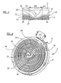
- a radiant electric heater 2 such as for use underneath a cooking surface 4, for example of glass-ceramic material, comprises a metal dish-like support 6 having therein a base layer 8 of thermal and electrical insulation material, such as microporous thermal and electrical insulation material.
- a radiant electric heating element is provided comprising an elongate corrugated electrically conductive ribbon 10, such as of iron-chromium-aluminium alloy, having spaced-apart legs 12 integral with or secured thereto and extending edgewise therefrom.
- the ribbon 10 is mounted edgewise on the base layer 8 and secured by at least partial embedding of the legs 12 in the surface of the base layer 8.
- a peripheral wall 14 of insulation material is provided in the heater and has a top surface which may be arranged to contact a rear side of the cooking surface 4 in a cooking appliance.
- a rod-like temperature-responsive device 16 comprising a metal outer tube and extending partly across the heater from an edge thereof.
- the rod-like temperature-responsive device 16 is supported at the edge of the heater and has a free end 18 which is unsupported at an inner region of the heater.
- the rod-like temperature-responsive device 16 may comprise differentially-expanding components, which operate a switch means 20 provided at a periphery of the heater.
- the rod-like temperature-responsive device 16 may comprise a metal tube enclosing an electrical component (not shown) having an electrical parameter which changes with temperature.
- Such electrical component may be a resistance temperature detector, such as a platinum resistance temperature detector, whose electrical resistance changes as a function of temperature.
- the electrical component may be connected to external processing circuitry by means of lead wires passing through the metal tube of the device 16.
- An elongate recess 22, with sloping sides 24, 26, is provided in the surface of the base layer 8.
- the elongate recess 22 extends radially from the edge of the heater and beneath and along the length of the rod-like temperature-responsive device 16.
- the electrically conductive ribbon 10 is arranged to be supported in and to traverse the elongate recess 22 such that an upper edge 28 of the ribbon 10 substantially follows a contour of the surface of the recess 22.
- the upper edge 28 of the ribbon 10 at a region 30 underlying the temperature-responsive device 16 is arranged at a predetermined distance from the temperature-responsive device 16 and is provided at a lower level relative to the upper edge 28 of the ribbon 10 at regions 32, 34 at either side of the recess 22.
- the angle and dimensions of the sloping sides 24, 26 of the recess 22 are selected in accordance with a depth required for the recess 22 and to facilitate turning of the ribbon 10 into and out of the recess 22.
- the free end 18 of the rod-like temperature-responsive device 16 may undergo displacement in a direction towards the base layer 8 in the event that the heater 2 is subjected to mechanical shock load conditions.
- the rod-like temperature-responsive device 16 when mounted on the heater may not be parallel to the surface of the base layer 8, due to manufacturing tolerances, and such that it slopes downwardly towards the base 8.
- it is arranged for greater clearance to be provided between the ribbon 10 and the rod-like temperature-responsive device 16 at the free end region 18 of the temperature-responsive device 16 than at the end thereof near the edge of the heater.
- the elongate recess 22 is arranged, such as by being ramped, to have a depth which gradually increases with increasing distance from the edge of the heater. This is particularly illustrated in Figures 2 and 3.
- Figure 2 represents a cross-sectional view of the heater 2 at a region near the edge of the heater
- Figure 3 represents a cross-sectional view of the heater 2 at an inner region of the heater, near the free end 18 of the rod-like temperature-responsive device 16.
- a distance D1 is provided between the region 30 of the upper edge 28 of the ribbon 10 and the rod-like temperature-responsive device 16 at the region of the heater near the peripheral edge thereof.
- a distance D2 which is greater than the distance D1 of Figure 2 is provided between the region 30 of the upper edge 28 of the ribbon 10 and the temperature-responsive device 16, at the inner region of the heater near the free end 18 of the rod-like temperature-responsive device 16.
- the recess 22 In order to maintain a substantially constant angle of slope of the sloping sides 24, 26 of the recess 22, while accommodating the gradually increasing depth of the recess 22 with increasing distance from the edge of the heater, it is suitably arranged for the recess 22 to gradually increase in width with increasing distance from the edge of the heater. Accordingly, the width W1 of the recess 22 at a region near the edge of the heater is made less than the width W2 at an inner region of the heater near the free end 18 of the temperature-responsive device 16.
- the recess 22 is therefore arranged to taper in width as well as being ramped in depth and the resulting form thereof is substantially that of a shell or scallop.
- An end region 36 of the elongate recess 22 may terminate in any desired form, such as a wall form, or be of stepped or sloping form.
- the arrangement of the recess 22 and the rod-like temperature-responsive device 16 is further advantageous in that it minimises or reduces any tendency for the ribbon-form heating element 10 to operate with a higher temperature in the region directly beneath the rod-like temperature-responsive device 16, compared with regions elsewhere in the heater.
Landscapes
- Chemical & Material Sciences (AREA)
- Engineering & Computer Science (AREA)
- Ceramic Engineering (AREA)
- Resistance Heating (AREA)
- Surface Heating Bodies (AREA)
Claims (12)
- Elektrische Strahlungsheizung (2), die Folgendes umfasst:eine Basis (8) aus thermischem und elektrischem Isoliermaterial mit einer Oberfläche, die wenigstens ein elektrisches Heizelement abstützt;eine stabartige temperaturempfindliche Vorrichtung (16), die sich längs über die Heizung (2) von einem Rand davon und über dem wenigstens einen elektrischen Heizelement (10) erstreckt;wobei die Oberfläche der Basis (8) eine längliche Aussparung (22) mit schräg verlaufenden Seiten (24, 26) aufweist, die unterhalb und entlang der Länge der stabartigen temperaturempfindlichen Vorrichtung (16) verläuft, wobei das wenigstens eine elektrische Heizelement in der länglichen Aussparung (22) getragen wird und diese überquert, so dass ein oberer Rand (28) des wenigstens einen Heizelements im Wesentlichen einer Kontur der Oberfläche der Aussparung folgt und wobei der obere Rand (28) des Heizelements in einer Region (30) unterhalb der stabartigen temperaturempfindlichen Vorrichtung (16) in einem vorbestimmten Abstand von der stabartigen temperaturempfindlichen Vorrichtung (16) vorgesehen ist und sich in einer geringeren Höhe relativ zum oberen Rand (28) des wenigstens einen Heizelements in Regionen (32, 34) auf beiden Seiten der länglichen Aussparung (22) befindet, wobei das wenigstens eine Heizelement in den Regionen (32, 34) auf beiden Seiten der länglichen Aussparung (22) auf einer im Wesentlichen planaren Oberfläche der Basis vorgesehen ist,dadurch gekennzeichnet, dass:das wenigstens eine elektrische Heizelement wenigstens ein längliches elektrisch leitendes Band (10) umfasst, wobei das wenigstens eine elektrisch leitende Band (10) hochkant abgestützt wird;die stabartige temperaturempfindliche Vorrichtung (16) teilweise über die Heizung (2) verläuft; unddie längliche Aussparung (22) eine Breite hat, die mit zunehmender Entfernung vom Rand der Heizung (2) zunimmt.
- Heizung nach Anspruch 1, dadurch gekennzeichnet, dass die stabartige temperaturempfindliche Vorrichtung (16) Metall, zum Beispiel eine Metallröhre, umfasst.
- Heizung nach einem der vorherigen Ansprüche, dadurch gekennzeichnet, dass die stabartige temperaturempfindliche Vorrichtung (16) ein erstes Ende, das in einer Randregion der Heizung (2) abgestützt wird, und ein zweites Ende (18) hat, das in einer Innenregion der Heizung (2) im Wesentlichen nicht abgestützt wird.
- Heizung nach einem der vorherigen Ansprüche, dadurch gekennzeichnet, dass die längliche Aussparung (22) eine Tiefe hat, die mit zunehmender Entfernung vom Rand der Heizung (2) zunimmt.
- Heizung nach Anspruch 4, dadurch gekennzeichnet, dass ein im Wesentlichen konstanter Winkel der schräg verlaufenden Seiten (24, 26) der länglichen Aussparung (22) beibehalten wird, während die Tiefe der länglichen Aussparung (22) mit zunehmender Entfernung vom Rand der Heizung (2) zunimmt.
- Heizung nach einem der vorherigen Ansprüche, dadurch gekennzeichnet, dass die längliche Aussparung (22) eine Form hat, die im Wesentlichen aus einer Muschel- oder Kammmuschelform ausgewählt ist.
- Heizung nach einem der vorherigen Ansprüche, dadurch gekennzeichnet, dass das wenigstens eine elektrisch leitende Band (10) eine gewellte Form hat.
- Heizung nach einem der vorherigen Ansprüche, dadurch gekennzeichnet, dass das wenigstens eine elektrisch leitende Band (10) mit einer Mehrzahl von voneinander beabstandeten Schenkeln (12) versehen ist, die an das wenigstens eine elektrisch leitende Band (10) zum Beispiel angeformt oder daran befestigt sind, wobei sich die Schenkel (12) von dem wenigstens einen elektrisch leitenden Band (10) hochkant erstrecken und wenigstens teilweise in der Oberfläche der Basis (8) eingebettet sind.
- Heizung nach Anspruch 8, dadurch gekennzeichnet, dass die Schenkel (12) in der Oberfläche der Basis (8) auf im Wesentlichen dieselbe Tiefe in der länglichen Aussparung (22) teilweise eingebettet sein wie anderswo auf der Basis (8).
- Heizung nach einem der vorherigen Ansprüche, dadurch gekennzeichnet, dass die Basis (8) ein mikroporöses thermisches und elektrisches Isoliermaterial umfasst.
- Heizung nach einem der vorherigen Ansprüche, dadurch gekennzeichnet, dass die Basis (8) in einem schalenartigen Träger (6), zum Beispiel aus Metall, vorgesehen ist.
- Heizung nach einem der vorherigen Ansprüche, dadurch gekennzeichnet, dass sie für eine Platzierung unterhalb einer Kochfeldfläche (4), z.B. eine Kochfeldfläche (4) aus glaskeramischem Material, ausgelegt ist.
Applications Claiming Priority (3)
| Application Number | Priority Date | Filing Date | Title |
|---|---|---|---|
| GBGB0301169.9A GB0301169D0 (en) | 2003-01-18 | 2003-01-18 | Radiant electric heater |
| GB0301169 | 2003-01-18 | ||
| PCT/GB2004/000119 WO2004066677A1 (en) | 2003-01-18 | 2004-01-16 | Radiant electric heater |
Publications (2)
| Publication Number | Publication Date |
|---|---|
| EP1588585A1 EP1588585A1 (de) | 2005-10-26 |
| EP1588585B1 true EP1588585B1 (de) | 2007-03-07 |
Family
ID=9951380
Family Applications (1)
| Application Number | Title | Priority Date | Filing Date |
|---|---|---|---|
| EP04702740A Expired - Lifetime EP1588585B1 (de) | 2003-01-18 | 2004-01-16 | Elektrischer strahlungsheizer |
Country Status (6)
| Country | Link |
|---|---|
| US (1) | US7403703B2 (de) |
| EP (1) | EP1588585B1 (de) |
| DE (1) | DE602004005160T2 (de) |
| ES (1) | ES2281779T3 (de) |
| GB (1) | GB0301169D0 (de) |
| WO (1) | WO2004066677A1 (de) |
Families Citing this family (1)
| Publication number | Priority date | Publication date | Assignee | Title |
|---|---|---|---|---|
| GB0301169D0 (en) * | 2003-01-18 | 2003-02-19 | Ceramaspeed Ltd | Radiant electric heater |
Family Cites Families (8)
| Publication number | Priority date | Publication date | Assignee | Title |
|---|---|---|---|---|
| DE3143692A1 (de) | 1981-11-04 | 1983-05-11 | Ego Elektro Blanc & Fischer | Strahlheizkoerper zur beheizung von koch- und waermeflaechen |
| DE3908600C2 (de) | 1989-03-16 | 1997-01-30 | Ako Werke Gmbh & Co | Strahlungsheizeinrichtung |
| GB2335834B (en) | 1998-03-26 | 2002-10-23 | Ceramaspeed Ltd | Radiant electric heater |
| GB2336985A (en) * | 1998-04-30 | 1999-11-03 | Ceramaspeed Ltd | A radiant electric heater having both a lamp-form heating element and a ribbon heating element |
| GB2340715B (en) | 1998-08-14 | 2003-01-29 | Ceramaspeed Ltd | Radiant electric heater |
| GB2361160B (en) * | 2000-04-03 | 2004-11-03 | Ceramaspeed Ltd | Radiant electric heater |
| GB0217351D0 (en) * | 2002-07-25 | 2002-09-04 | Ceramaspeed Ltd | Radiant electric heater |
| GB0301169D0 (en) * | 2003-01-18 | 2003-02-19 | Ceramaspeed Ltd | Radiant electric heater |
-
2003
- 2003-01-18 GB GBGB0301169.9A patent/GB0301169D0/en not_active Ceased
-
2004
- 2004-01-16 EP EP04702740A patent/EP1588585B1/de not_active Expired - Lifetime
- 2004-01-16 WO PCT/GB2004/000119 patent/WO2004066677A1/en not_active Ceased
- 2004-01-16 ES ES04702740T patent/ES2281779T3/es not_active Expired - Lifetime
- 2004-01-16 DE DE602004005160T patent/DE602004005160T2/de not_active Expired - Lifetime
- 2004-01-16 US US10/542,286 patent/US7403703B2/en not_active Expired - Lifetime
Also Published As
| Publication number | Publication date |
|---|---|
| ES2281779T3 (es) | 2007-10-01 |
| DE602004005160T2 (de) | 2007-11-15 |
| EP1588585A1 (de) | 2005-10-26 |
| WO2004066677A1 (en) | 2004-08-05 |
| GB0301169D0 (en) | 2003-02-19 |
| US7403703B2 (en) | 2008-07-22 |
| DE602004005160D1 (de) | 2007-04-19 |
| US20060186111A1 (en) | 2006-08-24 |
Similar Documents
| Publication | Publication Date | Title |
|---|---|---|
| EP0552860B1 (de) | Vorrichtung zur Steuerung oder Begrenzung der Temperatur in einem elektrischen Kochgerät | |
| EP1850101A1 (de) | Temperatursondenanordnung | |
| EP1488666B1 (de) | Elektrische heizbaugruppe | |
| EP1400151B1 (de) | Kochgerät | |
| JP2006527378A (ja) | 電熱装置用の温度検出装置 | |
| GB2275161A (en) | A radiant electric heating element | |
| JPH06101850A (ja) | 調理用レンジのための電気加熱装置 | |
| EP1266544B1 (de) | Temperatursensor | |
| GB2103910A (en) | Improvements in electric cookers incorporating radiant heaters | |
| GB1562251A (en) | Electrical heating units | |
| GB2069300A (en) | Radiant heating elements for smooth top cookers | |
| US7403703B2 (en) | Radiant electric heater | |
| EP0954202B1 (de) | Elektrischer Strahlungsheizkörper | |
| US6300604B1 (en) | Radiant electric heater | |
| US6018148A (en) | Radiant electric heater | |
| JP5021500B2 (ja) | 温度センサを備えた加熱装置及び加熱装置を備えたホブ | |
| US6051816A (en) | Radiant electric heater | |
| EP0973356A2 (de) | Elektrischer Strahlungsheizkörper | |
| WO1994024490A1 (en) | A hob | |
| EP1143770A2 (de) | Elektrischer Strahlungsheizkörper | |
| GB2324946A (en) | Radiant electric heater with visible radiation shielding | |
| WO2004066682A1 (en) | Radiant electric heater | |
| JPH0538555Y2 (de) | ||
| WO2008020176A1 (en) | Radiant electric heater | |
| WO2008020175A1 (en) | Radiant electric heater |
Legal Events
| Date | Code | Title | Description |
|---|---|---|---|
| PUAI | Public reference made under article 153(3) epc to a published international application that has entered the european phase |
Free format text: ORIGINAL CODE: 0009012 |
|
| 17P | Request for examination filed |
Effective date: 20050801 |
|
| AK | Designated contracting states |
Kind code of ref document: A1 Designated state(s): AT BE BG CH CY CZ DE DK EE ES FI FR GB GR HU IE IT LI LU MC NL PT RO SE SI SK TR |
|
| AX | Request for extension of the european patent |
Extension state: AL LT LV MK |
|
| DAX | Request for extension of the european patent (deleted) | ||
| RBV | Designated contracting states (corrected) |
Designated state(s): DE ES FR |
|
| GRAP | Despatch of communication of intention to grant a patent |
Free format text: ORIGINAL CODE: EPIDOSNIGR1 |
|
| GRAS | Grant fee paid |
Free format text: ORIGINAL CODE: EPIDOSNIGR3 |
|
| GRAA | (expected) grant |
Free format text: ORIGINAL CODE: 0009210 |
|
| AK | Designated contracting states |
Kind code of ref document: B1 Designated state(s): DE ES FR |
|
| REF | Corresponds to: |
Ref document number: 602004005160 Country of ref document: DE Date of ref document: 20070419 Kind code of ref document: P |
|
| REG | Reference to a national code |
Ref country code: ES Ref legal event code: FG2A Ref document number: 2281779 Country of ref document: ES Kind code of ref document: T3 |
|
| PLBE | No opposition filed within time limit |
Free format text: ORIGINAL CODE: 0009261 |
|
| STAA | Information on the status of an ep patent application or granted ep patent |
Free format text: STATUS: NO OPPOSITION FILED WITHIN TIME LIMIT |
|
| 26N | No opposition filed |
Effective date: 20071210 |
|
| PGFP | Annual fee paid to national office [announced via postgrant information from national office to epo] |
Ref country code: FR Payment date: 20080121 Year of fee payment: 5 |
|
| REG | Reference to a national code |
Ref country code: FR Ref legal event code: ST Effective date: 20091030 |
|
| PG25 | Lapsed in a contracting state [announced via postgrant information from national office to epo] |
Ref country code: FR Free format text: LAPSE BECAUSE OF NON-PAYMENT OF DUE FEES Effective date: 20090202 |
|
| REG | Reference to a national code |
Ref country code: DE Ref legal event code: R081 Ref document number: 602004005160 Country of ref document: DE Owner name: CERAMASPEED ACQUISITION CO. LTD., GB Free format text: FORMER OWNER: CERAMASPEED LTD., KIDDERMINSTER, WORCESTERSHIRE, GB Effective date: 20110502 Ref country code: DE Ref legal event code: R081 Ref document number: 602004005160 Country of ref document: DE Owner name: CERAMASPEED ACQUISITION CO. LTD., GB Free format text: FORMER OWNER: CERAMASPEED LTD., KIDDERMINSTER, GB Effective date: 20110502 |
|
| REG | Reference to a national code |
Ref country code: DE Ref legal event code: R082 Ref document number: 602004005160 Country of ref document: DE Representative=s name: JOACHIM MORITZ LUEDCKE, DE Ref country code: DE Ref legal event code: R082 Ref document number: 602004005160 Country of ref document: DE Representative=s name: LUEDCKE, JOACHIM MORITZ, DIPL.-ING., DE |
|
| REG | Reference to a national code |
Ref country code: DE Ref legal event code: R082 Ref document number: 602004005160 Country of ref document: DE Representative=s name: LUEDCKE, JOACHIM MORITZ, DIPL.-ING., DE |
|
| REG | Reference to a national code |
Ref country code: DE Ref legal event code: R082 Ref document number: 602004005160 Country of ref document: DE Representative=s name: LUEDCKE, JOACHIM MORITZ, DIPL.-ING., DE Effective date: 20130305 Ref country code: DE Ref legal event code: R082 Ref document number: 602004005160 Country of ref document: DE Representative=s name: LUEDCKE, JOACHIM MORITZ, DIPL.-ING., DE Effective date: 20120413 Ref country code: DE Ref legal event code: R081 Ref document number: 602004005160 Country of ref document: DE Owner name: CERAMASPEED ACQUISITION CO. LTD., GB Free format text: FORMER OWNER: STYLEWELL LTD., ABERCANAID, MERTHYR TYDFIL, GB Effective date: 20130305 Ref country code: DE Ref legal event code: R081 Ref document number: 602004005160 Country of ref document: DE Owner name: CERAMASPEED ACQUISITION CO. LTD., GB Free format text: FORMER OWNER: STYLEWELL LTD., ABERCANAID, GB Effective date: 20130305 |
|
| REG | Reference to a national code |
Ref country code: DE Ref legal event code: R081 Ref document number: 602004005160 Country of ref document: DE Owner name: EIKA, S. COOP., ES Free format text: FORMER OWNER: CERAMASPEED ACQUISITION CO. LTD., LONDON, GB Ref country code: DE Ref legal event code: R082 Ref document number: 602004005160 Country of ref document: DE Representative=s name: LUEDCKE, JOACHIM MORITZ, DIPL.-ING., DE |
|
| REG | Reference to a national code |
Ref country code: ES Ref legal event code: PC2A Owner name: CERAMASPEED ACQUISITION COMPANY LIMITED Effective date: 20200325 |
|
| PGFP | Annual fee paid to national office [announced via postgrant information from national office to epo] |
Ref country code: ES Payment date: 20200303 Year of fee payment: 17 Ref country code: DE Payment date: 20200327 Year of fee payment: 17 |
|
| REG | Reference to a national code |
Ref country code: DE Ref legal event code: R119 Ref document number: 602004005160 Country of ref document: DE |
|
| PG25 | Lapsed in a contracting state [announced via postgrant information from national office to epo] |
Ref country code: DE Free format text: LAPSE BECAUSE OF NON-PAYMENT OF DUE FEES Effective date: 20210803 |
|
| REG | Reference to a national code |
Ref country code: ES Ref legal event code: FD2A Effective date: 20220422 |
|
| PG25 | Lapsed in a contracting state [announced via postgrant information from national office to epo] |
Ref country code: ES Free format text: LAPSE BECAUSE OF NON-PAYMENT OF DUE FEES Effective date: 20210117 |