EP1588593B1 - Codiertes target für eine neutronenquelle - Google Patents
Codiertes target für eine neutronenquelle Download PDFInfo
- Publication number
- EP1588593B1 EP1588593B1 EP04701013A EP04701013A EP1588593B1 EP 1588593 B1 EP1588593 B1 EP 1588593B1 EP 04701013 A EP04701013 A EP 04701013A EP 04701013 A EP04701013 A EP 04701013A EP 1588593 B1 EP1588593 B1 EP 1588593B1
- Authority
- EP
- European Patent Office
- Prior art keywords
- neutron
- target
- emissive
- particle
- detector
- Prior art date
- Legal status (The legal status is an assumption and is not a legal conclusion. Google has not performed a legal analysis and makes no representation as to the accuracy of the status listed.)
- Expired - Lifetime
Links
Images




Classifications
-
- H—ELECTRICITY
- H05—ELECTRIC TECHNIQUES NOT OTHERWISE PROVIDED FOR
- H05H—PLASMA TECHNIQUE; PRODUCTION OF ACCELERATED ELECTRICALLY-CHARGED PARTICLES OR OF NEUTRONS; PRODUCTION OR ACCELERATION OF NEUTRAL MOLECULAR OR ATOMIC BEAMS
- H05H6/00—Targets for producing nuclear reactions
-
- H—ELECTRICITY
- H05—ELECTRIC TECHNIQUES NOT OTHERWISE PROVIDED FOR
- H05H—PLASMA TECHNIQUE; PRODUCTION OF ACCELERATED ELECTRICALLY-CHARGED PARTICLES OR OF NEUTRONS; PRODUCTION OR ACCELERATION OF NEUTRAL MOLECULAR OR ATOMIC BEAMS
- H05H3/00—Production or acceleration of neutral particle beams, e.g. molecular or atomic beams
- H05H3/06—Generating neutron beams
-
- Y—GENERAL TAGGING OF NEW TECHNOLOGICAL DEVELOPMENTS; GENERAL TAGGING OF CROSS-SECTIONAL TECHNOLOGIES SPANNING OVER SEVERAL SECTIONS OF THE IPC; TECHNICAL SUBJECTS COVERED BY FORMER USPC CROSS-REFERENCE ART COLLECTIONS [XRACs] AND DIGESTS
- Y02—TECHNOLOGIES OR APPLICATIONS FOR MITIGATION OR ADAPTATION AGAINST CLIMATE CHANGE
- Y02E—REDUCTION OF GREENHOUSE GAS [GHG] EMISSIONS, RELATED TO ENERGY GENERATION, TRANSMISSION OR DISTRIBUTION
- Y02E30/00—Energy generation of nuclear origin
- Y02E30/10—Nuclear fusion reactors
Definitions
- the present invention concerns a neutron source such as a neutron generat ing tube or a particle accelerator.
- Neutron generating tubes are mainly used to carry out imaging or analysis, for example in the nondestructive testing of objects.
- the neutrons make it possible to determine the presence of practically all of the elements in the periodic table.
- Particle accelerators such as linear accelerators supply neutrons with wide energy ranges.
- the applications may also be radiography applications or analysis of materials or even applications in nuclear medicine or in physics research.
- the neutrons are generated by a target when it is bombarded with a highly accelerated particle beam (see e.g. FR-A-2738669 ).
- the targets contain heavy isotopes of hydrogen: deuterium and / or tritium.
- a fusion nuclear reaction takes place between the nuclei of deuterium or tritium of the target and the accelerated particles from, in general, an ion source.
- the particles are hydrogen isotope ions.
- the ions are accelerated between two electrodes.
- the particles are also hydrogen ions (deuterium or tritium) or other heavier ions.
- the acceleration may be achieved by means of a succession of electrodes or by coupling in quadripolar radiofrequency accelerating cavities.
- the collision between a nucleus of deuterium and a nucleus of tritium supplies a neutron with an energy close to 14 MeV and an a particle with an energy of around 3.6 MeV.
- the neutrons are emitted in all directions, in other words in 4 ⁇ steradians.
- This mechanism also takes place with the reaction betwee n two deuterium nuclei.
- the energy of the neutron is in this case 2.45 MeV. It is associated with a particle of helium 3 of 0.8 MeV emitted in the opposite direction, at about a low angle.
- the targets In order for the nuclear reaction efficiency to be high, the targets should have a high density of nuclei.
- the particle beam also has to be sufficiently intense and homogeneous. One therefore tends to focus the particle beam and make it bombard a small homogeneous target.
- a compromise has to be found between the lifetime of the target and the efficiency. Indeed, for a total given emission, the lifetime of a target is proportional to its surface area. Moreover, it is not easy to focus the particle beam with precision. Said focusing must be consistent with the geometry of the target.
- FIG. 1A shows, in an image plane 5, the image 3 of a point 1 of an object 4, given by a point target 2.
- the target 2' is no longer point shaped but instead extended.
- the image 3' of the point object 1 in the image plane 5 is a lot bigger than in Figure 1A , which leads to an overall image of the object which will be blurred.
- the aim of the present invention is, as a matter of fact, to propose a neutron source that does not have the limitations and difficulties cited above.
- One aim of the invention is to form a target that has both a longer lifetime and an acceptable efficiency.
- Another aim of the invention is to form a target that does not need to be associated with a precisely focused particle beam.
- a further aim of the invention is to provide a target suited to delivering a higher flow of neutrons than that of point targets.
- the invention is a neutron source with a target intended to emit neutrons when it is bombarded with particles and said target comprises neutron emissive parts and neutron non -emissive parts which are juxtaposed, said emissive and non-emissive parts forming a pattern of the type of that of a coded mask.
- the emissive parts may be formed from at least one metal hydride, the metal of the metal hydride being deposited on a support in non -hydrogen fixing material through a stencil.
- the target may comprise an extended neutron emissive zone formed from at least one metal hydride, said extended zone cooperating with a mask in neutron non-emissive material, the non -emissive material of the mask partially covering up the extended emissive zone vis-a-vis the particles and forming non - emissive parts.
- the extended emissive zone may be supported by a support in a non-hydrogen fixing material.
- the non-hydrogen fixing material of the support may be chosen from among copper, silver or gold, said metals being used alone or in combination.
- the metal of the metal hydride may be chosen from among titanium, zirconium, erbium, scandium and vanadium.
- the non-emissive material of the mask may be chosen from among molybdenum, steel, iron, copper, tungsten or tantalum, said metals being used alone or in combination.
- the present invention also concerns a particle accelerator which comprises a neutron source thus defined.
- the present invention also concerns a neutron generating tube which comprises a target thus defined .
- the present invention also concerns the application of the neutron generating tube thus defined to transmission radiography, in which the target cooper ates with geometric deconvolution means to decode an untreated image given by the neutrons having crossed through an object to be radiographied in a reconstructed image of the object.
- the present invention also concerns the application of the particle accelerator thus defined to transmission radiography, in which the target cooperates with geometric deconvolution means to decode an untreated image given by the neutrons having crossed through an object to be radiographied in a reconstructed image of the object.
- the present invention also concerns a neutron generating tube thus defined, said tube being equipped with an a particle detector associated with the emission of neutrons.
- the present invention also concerns a particle accelerator thus defined, said accelerator being equipped with an ⁇ particle detector associated with the emission of particles.
- the ⁇ particle detector may comprises a plurality of pixels arranged in a matrix.
- the target may be inclined in relation to the direction of the particles that are bombarding it in order to facilitate the detection of ⁇ particles without overly disrupting the interaction of the particle beam in the target.
- the target may be substantially parallel to the ⁇ particle detector.
- the present invention also concerns the application of the neutron generating tube thus defined with an ⁇ particle detector to the analysis of substances and/or the imaging of substances that may be hidden, the tube cooperating with at least one ⁇ radiation detector and geometric deconvolution means for a gamma pseudo -image obtained by coincidence of gamma events and ⁇ parti cles detected by the ⁇ particle detector.
- the present invention also concerns the application of the particle accelerator thus defined with an ⁇ particle detector to the analysis of substances and/or the imaging of substances that may be hidden, the accelerator cooperating with at least one ⁇ radiation detector and geometric deconvolution means for a gamma pseudo-image obtained by coincidence of gamma events and a particles detected by the ⁇ particle detector.
- the present invention also concerns the application of the neutron generating tube thus defined with an ⁇ particle detector to the imaging of substances that may be hidden, the tube cooperating with at least one neutron detector.
- the present invention also concerns the application of the particle accelerator thus defined with an ⁇ particle detector to the imaging of substances that may be hidden, the accelerator cooperating with at least one neutron detector.
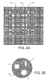
- FIG. 2 shows a front view of an example of a target 10. It comprises juxtaposed emissive parts 11 and non-emissive parts 12, said emissive parts 11 and non-emissive parts 12 forming a pattern of the type of that of a coded mask.
- a coded mask is a mask that is pierced with a plurality of holes placed i n a more or less random manner.
- the surface area of said holes may attain 50% or more of the total surface area of the mask.
- Coded masks are used in the medical field or in astronomy in telescopes. In these applications, the coded masks are placed between the object to be observed (planet, star) and the observer (or the device capturing the image).
- the emissive parts 11 of the target 10 correspond to the holes that the coded mask would have and the non-emissive parts 12 correspond to the solid parts of the coded mask. Obviously, the reverse is possible.
- Each emissive part 11 may also be considered as a pinhole. All of the emissive parts 11 together constitute a multi pinhole.
- the emissive parts 11 may be assimilated to point shaped target s and the whole target 10 to a quasi -point shaped target.
- the pattern represented in Figure 2A is relatively complex and other coded mask patterns may be used, such as that illustrated in Figure 2B , which only comprises three emissive parts 11, o ne substantially circular, a second substantially square and a third substantially rectangular.
- Said neutron source 23 may be a neutron generating tube or a particle accelerator. It comprises a jacket 21, the target 10 and an ion source 22, for example a Penning source type, in which deuterium or a mixture of deuterium and tritium is ionised. The ions are accelerated between the ion source 22 and the target 10 by acceleration means, which are not represented for reasons of clarity.
- the pattern of the target 10 is simpler than in Figure 2A .
- the target 10 is going to emit a heterogeneous flow of neutrons 13.
- the flow of neutrons 13 is divided into a plurality of secondary flows 13.1, 13.2 and said secondary flows are only initiated in order not to overcrowd the figure.
- the flow of neutrons 13 emitted will "convey" with it the pattern of the target 10 through an object 4 to be examined or analysed.
- the target 10 which plays the role of a coded mask, is not inserted between the object and an observer as in normal applications of coded masks but it is placed upstream of the object.
- the flow of neutrons 13 is a flow marked or coded by the pattern of the target 10.
- an image 30 of a point 1 of an object 4, given by the target 10 according to the invention is projected on an image plane 5.
- the image obtained 30 in the image plane 5 is an untreated image of the object 4 and said untreated image must be treated in order to obtain a reconstructed image 31.
- the untreated image comprises as many superimposed images of the object as there are emissive parts in the target, each of said emissive parts acting like a point target.
- the untreated image 30 may be acquired, for example, by a neutron detector 33 configured as a matrix, formed from materials sensitive to rapid neutrons such as recoil proton scintillating materials.
- the treatment is called geometric deconvolution and is performed in a computerised manner by means of an appropriate algorithm.
- Means of treating the untreated image 30 are shown schematically with the reference 32.
- the untreated image 30 obtained conveys two items of information, one relating to the pattern of the target 10 and the other relating to the transparency of the object 4.
- Deconvolution consists in separating the two items of information. It is a well known method and widely used in optics or in techniques using coded masks. This treatment is possible because the pattern of the target 10 is known by experimentation, modelling or calculation.
- the intensity of each point of the untreated image is the integral on the object of the product of the transparency of each point 1 of the object 4 multiplied by a term depending on the target 10.
- the Fourier transform of the untreated image is the product of the Fourier transforms of the object and an image of the target 10 obtained through an infinitely small pinhole.
- a pinhole is, in photograph, a small hole placed in a screen arranged in place of the objective of a photographic device.
- the choice of the pattern of the target makes it possible to carry out this division correctly.
- a traditional extended target which is emissive in a uniform manner, the differences bet ween neighbouring points of the object do not stand out. Other calculation methods exist; they enable the same result to be obtained.
- the reconstructed image 31 of the object 4 (or the point 1 of the object) obtained after geometric deconvolution is substantially that which one would have obtained if one had used a point target.
- the target according to the invention has dimensions greater that those of the point target which would have given the same image, it has a longer lifetime compared to the point target.
- the gain in lifetime may be very important because the ratio of surface areas between the target according to the invention and the point target which would have given the same image may attain, depending on the case, factors of one hundred -fold or one thousand-fold. The flow of neutrons is thus increased compared to that of the point target.
- a target according to the invention makes it possible to obtain much better reconstructed image quality than a conventional homogeneous target.
- the pattern of the target 10 appears on the image plane 5 in a more or less intense manner depending on whether the object 4 allows the neutron flow to pass to a greater or lesser extent.
- the difference between the untreated image 30 obtained with the transmission radiography installation in Figure 3A and that in Figure 3B is only at the level of its intensity.
- the untreated image 30 in Figure 3B is less intense than that in Figure 3A . This means that the object that has given the untreated image 30 in Figure 3B is less transparent to neutrons than that shown in Figure 3A .
- the target comprises a non -emissive support 14, in non-hydrogen fixing material.
- Said material may be chosen from among copper, silver, gold or other, said metals being used alone or in combination.
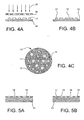
- Said stencil 16 has a pattern that corresponds to that which the target should have, in other words a pattern of the type of that of coded masks.
- Said stencil 16 may be formed from metal such as iron or aluminium for example.
- the hydrogen fixing material 15 forms blocks 17 on the support 14. Said blocks 17 are going to contribute to forming the emissive parts 11 of the target. The parts of the support 14 located between the blocks 17 are going to form the non - emissive parts 12 of the target.
- the hydrogen fixing material may be deposited, for example , by cathode sputtering, vacuum evaporation or other method. The thickness of the blocks 17 is typically several micrometers.
- the support 14 equipped with blocks 17 is then brought into the presence of hydrogen so that the block 17 material traps the hydrogen and fixes it.
- the hydrogen fixed blocks 17 are represented in Figure 4B .
- FIG. 4C shows a front view of a finished target, in the form of a disc.
- Figures 5A and 5B show another embodiment of a target.
- the support 14 in non-hydrogen fixing material is shown.
- Said support 14 is covered in a uniform manner with a metallic hydrogen fixing material 18.
- metallic hydrogen fixing material one may use, for example, titanium, zirconium, erbium, scandium or vanadium, said metals being used alone or in combination.
- Said deposition may be carried out by sputtering or as in the previous example.
- the hydrogen fixing material 18 is covered with a mask 19 that comprises a pattern of the type of that of a coded or multi-pinhole mask.
- Said mask 19 is formed of a material that does not emit neutrons, which does not sputter or which sputters as little as possible when it is bombarded by particles and which is compatible with vacuum techniques.
- Said material may be, for example, chosen from among molybdenum or copper, iron, tungsten, tantalum or steel, said metals being used alone or in combination.
- the mask 19 is substantially parallel with the surface of the layer 18. A gap of around one millimetre or more can separate the mask 19 and the layer 18. Obviously, the mask may be in contact with the hydrogen fixing material instead of being slightly separated.
- the assembly formed of the support 14, the layer 18 and the mask 19 is then brought into the presence of hydrogen so that the layer 18. traps the hydrogen and fixes it.
- This hydrogen fixing step takes place, as previously, while the target is placed in a vacuum jacket (which is that of the tube or accelerator that uses the target) containing a gaseous mixture of tritium and / or deuterium under low pressure.
- the layer 18 then forms an extended zone capable of emitting neutrons but it is partially masked by the mask 19.
- the hydrogen fixed material of the layer 18 located at the openings of the mask 19 forms the emissive parts 11 of the target whereas the solid parts of the mask 19 form the non -emissive parts 12 of the target.
- the parts of layer 18 placed behind the solid parts of the mask 19 are inactive even though impregnated with hydrogen. Obviously, it is possible for the hydrogen fixing of the layer 18 to take place before the application of the mask 19.
- the particle beam which is going to bombard the hydrogen fixed layer 18 in order to make it emit neutrons is coded because it is going to be partially stopped by the mask 19 and only reach the emissive parts 11.
- the neutron beam is also coded since only the emissive parts 11 are going to emit neutrons.
- Such targets may be integrated into a neutron generating tube, particularly to carry out rapid neutron transmission radiography.
- the energy of the neutrons may be 14 MeV or 2.45 MeV.
- the reconstructed image then has a resolution comparable to that obtained with a point target and an intensity substantially equal to n times that obtained with a point target, where n is the number of emissive parts 11 of the target.
- the target may be included in a particle accelerator such as that represented in Figure 6 .
- Said accelerator comprises a tubular body 60 cooperating with pumping means 61 for extracting the non-ionised gas and cooling means 62.
- At one of the ends of the accelerator is placed means of injecting 63 an ion beam 64 (protons or deuterons).
- At the other end is placed the target 65 according to the invention that is to be bombarded.
- the focusing means referenced 66 may be formed by electrodes.
- the acceleration means referenced 67 may be formed for example by various high voltage devices. This type of particle accelerator finds application in neutron radiography or the analysis of matter.
- a target in a neutron generating tube having associated particles in other words a neutron generating tube equipped with an ⁇ particle s detector.
- An example of this type of tube is represented in Figure 7A .
- a particularly interesting application of this type of associated particles tube is the imaging and/or the analysis of substances such as the detection of mines in the ground, the detection of illicit materials or explosives in various containers.
- a neutron generating tube equipped with an ⁇ particle detector is known for example from the patent application FR-A1-2 738 669 in the applicant's name.
- Said neutron generating tube is equipped with an ⁇ particle detector which cooperates with the means of focusing the ⁇ particles emitted by a uniform emission target.
- the means of focusing may be a coded mask type and be placed in the path of the ⁇ particles. In the present invention, it is either the ions projected on the target that are coded in the case of the mask, or the target itself which is coded.
- the tube comprises a vacuum jacket 41 intended to contain a gaseous mixture of tritium and/or deuterium under low pressure (of around several tenths of Pascals).
- the getter referenced 42 enables the supply of a gaseous mixture and acts as a pressure regulator.
- the jacket 41 is sealed by an electrically insulating part 43 which is crossed by high voltage connections 44 for the energy supply for an ion source 45 placed in said jacket 41. Said ion source 45 ionises the gaseous mixture present in said jacket 41.
- Said ion source 45 is intended to produce ions that form an ion beam 46 directed towards the patterned target 47 of the invention when they are accelerated by an accelerating electrode 48 placed between the ion source 45 and the patterned target 47.
- Said ion source 45 may be a Penning type one and comprises an anode 71, a cathode 72 and a permanent magnet 73 which creates a magnetic field normal to the electric field established between the cathode 72 and the anode 71.
- a ferromagnetic casing 74 surrounds the cathode 72 and the anode 71 and guides the magnetic field generated by the magnet 7 3 so that it re-closes at the level of an air gap crossed by the ion beam 46.
- the jacket 41 also contains an ⁇ particle detector 49 formed, for example, of a plurality of junction diodes or a scintillator or a series of scintillating optic fibres sensitive to ⁇ particles and insensitive to neutrons and photons.
- the scintillator may be assoc iated with a photomultiplier tube or a microchannel wafer device (not represented).
- the patterned target 47 may be inclined in relation to the ion beam 46, for example by around 45°, in order to optimise the detection of ⁇ particles without disrupting the ion beam 46 - target 47 interaction.
- the ⁇ particle detector 49 is inclined in relation to the target 47; it is directed substantially like the particle beam 46. It could be substantially parallel to the target as shown in Figure 8C .
- a particle accelerator may include an ⁇ particle detector as illustrated in Figures 7B and 7C .
- the ⁇ particle detector is referenced 69. It may be the same type as that described in Figure 7A .
- the target 65 is inclined in relation to the ion beam 64 whereas in Figure 7C , it is normal to the ion beam 64.
- FIGs 8A and 8B schematically illustr ate installations for imaging and/or analysis materials, which may be hidden, using a conventional neutron generating tube 53 having associated particles.
- the neutron generating tube 53 is a point target 53 and in Figure 8B it is an extended target 56'.
- the ion source is referenced 54 and the ion beam that it produces 55.
- the ion source 54 and the target 56 or 56' are contained within a vacuum jacket 57.
- the jacket also contains an ⁇ particle detector 58.
- the reference 51 illustrates an object in which one wishes to analyse the material and/or which one wishes to view in one or two dimensions.
- At least one ⁇ radiation detector 50 is placed near to the object 51. The analysis of the ⁇ spectrum obtained provides information on the composition, chemical element by chemical element, of the materials encountered by the neutron flow emitted by the tube in a given volume of material bombarded with neutrons.
- One aims to determine the constitution and / or to obtain a pseudo-image of an object placed at a distance h from the target 56, 56'.
- Said pseudo -image in two or three dimensions is called a pseudo -image because it is an indirect image of the object. It is not given by the neutrons that cross through the object but by the ⁇ radiation gathered near to the object. It is representative of its chemical constitution.
- the distance h corresponds to a time of flight t for the neutrons emitted by the target 56, 56'.
- Said time of flight t is known from the speed of a neutron (5.2 cm/s for neutrons of 14 MeV energy), from its moment of departure known through the detection of the associated a particle which has, for its part, a speed of 1.3 cm/s.
- ⁇ events detected by staid ⁇ radiation detector 50 associated with this characteristic time of flight t.
- Said ⁇ events are all linked to the detection of ⁇ particles by the detector 58 composed of a plurality of pixels 76 arranged in a matrix.
- Said ⁇ particle detector and the ⁇ radiation detector are linked to treatment means 59 which determine the ⁇ events in coincidence with a pixel p x,y for a given time of flight t.
- Calculation means 70 (for example, a personal computer type) connected to the output of the treatment means 59 make it possible to carry out a spectral analysis of the object 51.
- Spectral deconvolution means 75 connected to the calculation means 70 deliver the pseudo-image in two dimensions or in three dimensions of the object 51, chemical element by chemical element.
- the resolution of the pseudo-image depends on the size of the target.
- Figure 8A illustrates the case of a point target 56.
- one p x,y of the pixels 76 of the ⁇ particle detector 58 receives the ⁇ particles which come from the neutrons n emitted by the point target 56 and said ⁇ particles translate the interactions of neutrons n circulating in a straight line d which passes through the pixel p x,y and the point that constitutes the point target 56.
- the location of the pixel p x,y of the ⁇ particle detect or 58 makes it possible to know the trajectory of the neutrons n emitted simultaneously with the ⁇ particles in question since it is the straight line d.
- the ⁇ radiation spectrum obtained for the given time of flight t and for a ⁇ - ⁇ coincidence of the time width ⁇ t with the pixel p x,y is the characteristic spectrum of a volume of material, obtained by a projection in volume of the pixel p x,y through the point target 56.
- the thickness of the material of the volume is defined by the product of the speed of the neutrons multiplied by ⁇ t.
- a neutron generating tube 53 having a point target 56 has a short lifetime. One therefore tends to increase the surface area of the target.
- Figure 8B differs from Figure 8A by the fact that the target 56' in not a point target but a extended target. This is an extreme case.
- the location of an ⁇ particle on the ⁇ particle detector 58 by a pixel p x,y does not allow the path of the corresponding neutron n to be known. It can only be localised within the interior of a solid angle A, the summit of which is the pixel p x,y , which leans on the contour of the target 56' and which passes through the object 51. This configuration excludes the notion of sharp image.
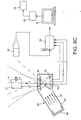
- Figure 8C illustrates an installation for imaging and/or analysing materials, which may be hidden, using with reference 82 a neutron source, either a neutron generating tube of the same type as that in Figure 7A or a particle accelerator of the same type as that in Figures 7B or 7C .
- Said tube or accelerator contains the patterned target 80.
- the remainder of the installation is similar to that represented in Figures 8A and 8B with the exception of the fact that the geometric deconvolution means 81 are inserted between the calculation means 70 and the spectral deconvolution means 75.
- the operating principle of such an installation is similar to that of the installation in Figure 8A with a multitude of distinct point targets.
- geometric deconvolution means 81 By analogy with the use of the neutron generating tube in Figure 3A , in the absence of geometric deconvolution means, one would obtain at each point of the image of the object 51, the mixed image of the object itself and of the patterned target.
- the geometric deconvolution means 81 for example taking the form of an inverse algorithm, enable the two mixed images to be separated.
- An elementary fragment (not represented) of material of the object 51 contributes to L pixels 76 of the ⁇ particle detector 58 and thus to L ⁇ spectra. Everything takes place as if the detection of ⁇ radiation from the object. 51 bombarded with the neutrons n was carried out by the ⁇ particle detector 58 itself, through a coded mask with the pattern of the target 80.
- the spectrum associated with each of the L pixels 76 of the ⁇ particle detector is a combination of M spectra corresponding to M elementary fragments of the object 51 through the intermediary of the target.
- M number of point targets
- L number of ⁇ pixels
- the ⁇ radiation detector 50 could be replaced by a neutron detector such as that bearing the reference 33 in Figure 3A .
- the principle of using the installation would be the same to carry out the imaging of substances that may be hidden. For this reason, it has not been added to the new figure.
- neutron generating tubes and particle accelerators it is possible to carry out direct imaging such as neutron radiography or indirect imaging such as analysis by ⁇ spectrometry and an associated particle tube.
- direct imaging such as neutron radiography
- indirect imaging such as analysis by ⁇ spectrometry and an associated particle tube.
- the coding of the target allows the coding of the image or the pseudo - image and obtaining a "pure" image or pseudo -image of the object, cleared of the aberrations due to the non -point nature of the targets formed in practice . Consequently, the invention makes it possible to produce systems that have both high geometric resolution and a long lifetime, which were not compatible previously.
Landscapes
- Physics & Mathematics (AREA)
- Spectroscopy & Molecular Physics (AREA)
- High Energy & Nuclear Physics (AREA)
- Engineering & Computer Science (AREA)
- Plasma & Fusion (AREA)
- Chemical & Material Sciences (AREA)
- Chemical Kinetics & Catalysis (AREA)
- Optics & Photonics (AREA)
- Particle Accelerators (AREA)
- Analysing Materials By The Use Of Radiation (AREA)
- Measurement Of Radiation (AREA)
- Luminescent Compositions (AREA)
Claims (23)
- Neutronenquelle, umfassend ein Target, das dazu ausgelegt ist, Neutronen zu emittieren, wenn es mit Partikeln beschossen wird, dadurch gekennzeichnet, dass es Neutronen-emittierende Teile (11) und nicht-Neutronen-emittierende Teile (12) umfasst, die nebeneinander angeordnet sind, wobei die emittierenden und die nicht-emittierenden Teile ein Muster von dem Typ desjenigen einer codierten Maske bilden, derart, dass die Quelle einen durch das Muster des Targets codierten Neutronenfluss emittiert.
- Neutronenquelle nach Anspruch 1, dadurch gekennzeichnet, dass die emittierenden Teile (11) aus wenigstens einem Metallhydrid gebildet sind, wobei das Metall (15) des Metallhydrids auf einem Träger (14) in nicht-wasserstoffbindendem Material durch eine Schablone (16) hindurch abgeschieden ist.
- Neutronenquelle nach Anspruch 1, dadurch gekennzeichnet, dass das Target eine ausgedehnte Neutronen-emittierende Zone (18) umfasst, die aus wenigstens einem Metallhydrid gebildet ist, wobei die ausgedehnte Zone (18) mit einer Maske (19) in nicht-Neutronen emittierendem Material kooperiert, wobei das nicht-emittierende Material der Maske (19) die ausgedehnte emittierende Zone teilweise gegenüber den Partikeln abdeckt und nicht-emittierende Teile (12) bildet.
- Neutronenquelle nach Anspruch 3, dadurch gekennzeichnet, dass die ausgedehnte emittierende Zone (18) durch einen Träger (14) in einem nicht-wasserstoffbindendem Material getragen wird.
- Neutronenquelle nach einem der Ansprüche 2 oder 4, dadurch gekennzeichnet, dass das nicht-wasserstoffbindende Material des Trägers (14) ausgewählt ist aus Kupfer, Silber oder Gold, wobei diese Metalle alleine oder in Kombination verwendet werden.
- Neutronenquelle nach einem der Ansprüche 1 bis 5, dadurch gekennzeichnet, dass das Metall des Metallhydrids ausgewählt ist aus Titan, Zirkon, Erbium, Skandium und Vanadium.
- Neutronenquelle nach Anspruch 3, dadurch gekennzeichnet, dass das nicht-emittierende Material der Maske (19) ausgewählt ist aus Molybdän, Stahl, Eisen, Kupfer, Wolfram und Tantal, wobei die Metalle alleine oder in Kombination verwendet werden.
- Partikelbeschleuniger, dadurch gekennzeichnet, dass er eine Neutronenquelle nach einem der Ansprüche 1 bis 7 umfasst.
- Anwendung des Partikelbeschleunigers nach Anspruch 8 in der Radiographie, wobei das Target (10) mit der geometrischen Entfaltungseinrichtung (32) kooperiert, um ein unbearbeitetes Bild (30), welches durch die Neutronen geliefert wird, die ein zu radiographierendes Objekt (4) durchquert haben, zu einem rekonstruierten Bild (31) des Objekts zu decodieren.
- Partikelbeschleuniger nach Anspruch 8, dadurch gekennzeichnet, dass er mit einem α-Partikel-Detektor (69) ausgestattet ist, der der Emission von Neutronen zugeordnet ist.
- Partikeibeschleuniger nach Anspruch 10, dadurch gekennzeichnet, dass der α-Partikel-Detektor (69) eine Mehrzahl von Pixeln (76) umfasst, die in einer Matrix angeordnet sind.
- Partikelbeschleuniger nach einem der Ansprüche 10 oder 11, dadurch gekennzeichnet, dass das Target (65) im Bezug zur Richtung der Partikel (64), mit denen es beschossen wird, geneigt ist.
- Partikelbeschleuniger nach einem der Ansprüche 10 bis 12, dadurch gekennzeichnet, dass das Target (80) im Wesentlichen parallel zum α-Partikel-Detektor (58) ist.
- Anwendung des Partikelbeschleunigers nach einem der Ansprüche 10 bis 13 in der Analyse von Substanzen und/oder Abbildung von Substanzen, die verborgen sein können, wobei der Beschleuniger kooperiert mit wenigstens einem Gamma-Strahlungsdetektor (50) und einer geometrischen Entfaltungseinrichtung (81) für ein Gamma-Pseudobild, das erhalten wird durch die Koinzidenz von Gamma-Ereignissen und α-Partikeln, die durch den α-Partikel-Detektor detektiert werden.
- Anwendung des Partikelbeschleunigers nach einem der Ansprüche 10 bis 13 in der Abbildung von Substanzen, die verborgen sein können, wobei der Beschleuniger mit einem Neutronendetektor kooperiert.
- Neutronenerzeugungsrohr, dadurch gekennzeichnet, dass es eine Neutronenquelle (10) nach einem der Ansprüche 1 bis 7 umfasst.
- Anwendung des Neutronenerzeugungsrohrs nach Anspruch 16 in der Radiographie, wobei das Target (10) mit der geometrischen Entfaltungseinrichtung (32) kooperiert, um ein unbearbeitetes Bild (30), welches durch die Neutronen geliefert wird, die ein zu radiographierendes Objekt (4) durchquert haben, zu einem rekonstruierten Bild (31) des Objekts zu decodieren.
- Neutronenerzeugungsrohr nach Anspruch 16, dadurch gekennzeichnet, dass es mit einem α-Partikel-Detektor (49) ausgestattet ist, der der Emission von Neutronen zugeordnet ist.
- Neutronenerzeugungsrohr nach Anspruch 18, dadurch gekennzeichnet, dass der α-Partikel-Detektor (49) eine Mehrzahl von Pixeln (76) umfasst, die in einer Matrix angeordnet sind.
- Neutronenerzeugungsrohr nach einem der Ansprüche 18 oder 19, dadurch gekennzeichnet, dass das Target (47) im Bezug zur Richtung der Partikel (64), mit denen es beschossen wird, geneigt ist.
- Neutronenerzeugungsrohr nach einem der Ansprüche 18 oder 19, dadurch gekennzeichnet, dass das Target (80) im Wesentlichen parallel zum α-Partikel-Detektor (58) ist.
- Anwendung des Neutronenerzeugungsrohrs nach einem der Ansprüche 18 bis 21 in der Analyse von Substanzen und/oder der Abbildung von Substanzen, die verborgen sein können, wobei das Rohr mit wenigstens einem Gamma-Strahlungsdetektor (50) und einer geometrischen Entfaltungseinrichtung (81) für ein Gamma-Pseudobild kooperiert, das durch eine Koinzidenz von Gamma-Ereignissen und α-Partikeln erhalten wird, die durch den α-Partikel-Detektor detektiert werden.
- Anwendung des Neutronenerzeugungsrohrs nach einem der Ansprüche 18 bis 21 in der Abbildung von Substanzen, die verborgen sein können, wobei das Rohr mit einem Neutronendetektor kooperiert.
Applications Claiming Priority (5)
| Application Number | Priority Date | Filing Date | Title |
|---|---|---|---|
| US44039203P | 2003-01-16 | 2003-01-16 | |
| US440392P | 2003-01-16 | ||
| US10/733,282 US20050135533A1 (en) | 2003-01-16 | 2003-12-12 | Coded target for neutron source |
| US733282 | 2003-12-12 | ||
| PCT/EP2004/050009 WO2004064462A1 (en) | 2003-01-16 | 2004-01-09 | Coded target for neutron source |
Publications (2)
| Publication Number | Publication Date |
|---|---|
| EP1588593A1 EP1588593A1 (de) | 2005-10-26 |
| EP1588593B1 true EP1588593B1 (de) | 2009-03-25 |
Family
ID=32718169
Family Applications (1)
| Application Number | Title | Priority Date | Filing Date |
|---|---|---|---|
| EP04701013A Expired - Lifetime EP1588593B1 (de) | 2003-01-16 | 2004-01-09 | Codiertes target für eine neutronenquelle |
Country Status (6)
| Country | Link |
|---|---|
| US (1) | US20050135533A1 (de) |
| EP (1) | EP1588593B1 (de) |
| AT (1) | ATE427027T1 (de) |
| DE (1) | DE602004020182D1 (de) |
| ES (1) | ES2324912T3 (de) |
| WO (1) | WO2004064462A1 (de) |
Families Citing this family (5)
| Publication number | Priority date | Publication date | Assignee | Title |
|---|---|---|---|---|
| WO2008148525A1 (en) * | 2007-06-05 | 2008-12-11 | John Sved | Neutron radiography apparatus and method |
| FR2945402B1 (fr) | 2009-05-06 | 2014-04-25 | Realisations Nucleaires Sa D Et | Generateur de neutrons a tube scelle, equipe de detecteurs de particules alpha, et systeme de mesure a particule associee utilisant le generateur |
| FR2945631B1 (fr) | 2009-05-13 | 2012-07-27 | Realisations Nucleaires Sa D Et | Procede d'analyse d'un objet par interrogation neutronique, par la technique de la particule associee, et dispositif pour la mise en oeuvre du procede. |
| US9274245B2 (en) | 2014-05-30 | 2016-03-01 | Baker Hughes Incorporated | Measurement technique utilizing novel radiation detectors in and near pulsed neutron generator tubes for well logging applications using solid state materials |
| US10462893B2 (en) | 2017-06-05 | 2019-10-29 | Neutron Therapeutics, Inc. | Method and system for surface modification of substrate for ion beam target |
Family Cites Families (15)
| Publication number | Priority date | Publication date | Assignee | Title |
|---|---|---|---|---|
| GB1131143A (en) * | 1964-12-17 | 1968-10-23 | British Cellophane Ltd | An improved x-ray gauging apparatus |
| GB1137475A (en) * | 1966-01-13 | 1968-12-18 | Rosemount Eng Co Ltd | Improvements in or relating to radiation responsive devices |
| DE2053881A1 (en) * | 1970-11-03 | 1972-05-10 | Nukem Gmbh | Target for neutron prodn - contg copper substrate and layer of erbium, yttrium or scandium impregnated with tritium int |
| US4209780A (en) * | 1978-05-02 | 1980-06-24 | The United States Of America As Represented By The United States Department Of Energy | Coded aperture imaging with uniformly redundant arrays |
| US4426722A (en) * | 1981-03-12 | 1984-01-17 | Bell Telephone Laboratories, Incorporated | X-Ray microbeam generator |
| US4918315A (en) * | 1988-01-11 | 1990-04-17 | Penetron, Inc. | Neutron scatter method and apparatus for the noninvasive interrogation of objects |
| FR2630251B1 (fr) * | 1988-04-19 | 1990-08-17 | Realisations Nucleaires Et | Generateur de neutrons a haut flux avec cible a grande duree de vie |
| US5076993A (en) * | 1990-01-12 | 1991-12-31 | Science Applications International Corporation | Contraband detection system using direct imaging pulsed fast neutrons |
| US5135704A (en) * | 1990-03-02 | 1992-08-04 | Science Research Laboratory, Inc. | Radiation source utilizing a unique accelerator and apparatus for the use thereof |
| IL111436A (en) * | 1993-11-19 | 1998-07-15 | Ail Systems Inc | Gamma ray imaging system |
| FR2738669B1 (fr) * | 1995-09-13 | 1997-10-10 | Sodern | Tube generateur de neutrons equipe d'un detecteur de particules alpha |
| AU3295097A (en) * | 1996-05-31 | 1998-01-05 | Massachusetts Institute Of Technology | Coded aperture imaging |
| US5838759A (en) * | 1996-07-03 | 1998-11-17 | Advanced Research And Applications Corporation | Single beam photoneutron probe and X-ray imaging system for contraband detection and identification |
| US6907097B2 (en) * | 2001-03-16 | 2005-06-14 | The Regents Of The University Of California | Cylindrical neutron generator |
| JP2003057469A (ja) * | 2001-04-11 | 2003-02-26 | Makoto Fujimaki | 光導波路グレーティング、その形成方法、およびその形成用マスク |
-
2003
- 2003-12-12 US US10/733,282 patent/US20050135533A1/en not_active Abandoned
-
2004
- 2004-01-09 ES ES04701013T patent/ES2324912T3/es not_active Expired - Lifetime
- 2004-01-09 AT AT04701013T patent/ATE427027T1/de not_active IP Right Cessation
- 2004-01-09 EP EP04701013A patent/EP1588593B1/de not_active Expired - Lifetime
- 2004-01-09 WO PCT/EP2004/050009 patent/WO2004064462A1/en not_active Ceased
- 2004-01-09 DE DE602004020182T patent/DE602004020182D1/de not_active Expired - Lifetime
Also Published As
| Publication number | Publication date |
|---|---|
| ES2324912T3 (es) | 2009-08-19 |
| ATE427027T1 (de) | 2009-04-15 |
| WO2004064462A1 (en) | 2004-07-29 |
| WO2004064462A9 (en) | 2005-03-31 |
| DE602004020182D1 (de) | 2009-05-07 |
| US20050135533A1 (en) | 2005-06-23 |
| EP1588593A1 (de) | 2005-10-26 |
Similar Documents
| Publication | Publication Date | Title |
|---|---|---|
| Folkmann | Analytical use of ion-induced X-rays | |
| Antolak et al. | Negative ion-driven associated particle neutron generator | |
| Jakubowski et al. | Measurements of charged particle beams from plasma focus discharges | |
| EP1588593B1 (de) | Codiertes target für eine neutronenquelle | |
| Spädtke | Invited Review Article: Modeling ion beam extraction from different types of ion sources | |
| Kruglov et al. | A beam diagnostic system for low-intensity radioactive beams | |
| Sadowski et al. | Formation and role of filaments in high-current discharges of the pinch type | |
| Sy | Advanced Penning-type ion source development and passive beam focusing techniques for an associated particle imaging neutron generator with enhanced spatial resolution | |
| Roshan et al. | High energy ion beams from the plasma focus | |
| Papka et al. | Cluster in nuclei: Experimental perspectives | |
| Asoka-Kumar et al. | An intense monoenergetic positron beam with an adjustable energy between 0.5 and 3.0 MeV | |
| Widmann et al. | Limits for two-photon and e+ e− decay widths of positron-electron scattering resonances for√ s= 1.78 to 1.92 MeV | |
| Nusair et al. | Accelerator mass spectrometry in laboratory nuclear astrophysics | |
| Seiferle | Characterization of the Th-229 nuclear clock transition | |
| MacMullin | Elastic and inelastic scattering of neutrons from neon and argon: Impact on neutrinoless double-beta decay and dark matter experimental programs | |
| Zidarova | Gamma-ray spectroscopy of neutron-rich scandium isotopes | |
| Berdemann et al. | Monoenergetic (e+ e−) pairs from heavy ion collisions | |
| John | A Preliminary Study of the Effect of the Chirped Rotating Wall on a Positron Cloud | |
| Baugher | Neutron-rich chromium and manganese isotopes and the role of the neutron 0g (9/2) and 1d (5/2) orbitals in the region below Nickel-68 | |
| Talebitaher et al. | Neutron and proton diagnostics for pulsed plasma fusion devices | |
| Alayed | The Decay of a Microsecond Seniority Isomer in 155Hf | |
| Han et al. | Design of Beta Coincidence Spectroscopy | |
| Bokeloh | Calibration of hot and cold dark matter experiments | |
| Stone Jr | Measurement of inclusive charm production in two-photon collisions at LEP | |
| Dunlop | High-Precision Half-Life Measurements for the Superallowed Beta+ Emitters 10C and 22Mg |
Legal Events
| Date | Code | Title | Description |
|---|---|---|---|
| PUAI | Public reference made under article 153(3) epc to a published international application that has entered the european phase |
Free format text: ORIGINAL CODE: 0009012 |
|
| 17P | Request for examination filed |
Effective date: 20050726 |
|
| AK | Designated contracting states |
Kind code of ref document: A1 Designated state(s): AT BE BG CH CY CZ DE DK EE ES FI FR GB GR HU IE IT LI LU MC NL PT RO SE SI SK TR |
|
| AX | Request for extension of the european patent |
Extension state: AL LT LV MK |
|
| DAX | Request for extension of the european patent (deleted) | ||
| GRAC | Information related to communication of intention to grant a patent modified |
Free format text: ORIGINAL CODE: EPIDOSCIGR1 |
|
| GRAP | Despatch of communication of intention to grant a patent |
Free format text: ORIGINAL CODE: EPIDOSNIGR1 |
|
| GRAS | Grant fee paid |
Free format text: ORIGINAL CODE: EPIDOSNIGR3 |
|
| GRAA | (expected) grant |
Free format text: ORIGINAL CODE: 0009210 |
|
| AK | Designated contracting states |
Kind code of ref document: B1 Designated state(s): AT BE BG CH CY CZ DE DK EE ES FI FR GB GR HU IE IT LI LU MC NL PT RO SE SI SK TR |
|
| REG | Reference to a national code |
Ref country code: GB Ref legal event code: FG4D |
|
| REG | Reference to a national code |
Ref country code: CH Ref legal event code: EP |
|
| REG | Reference to a national code |
Ref country code: IE Ref legal event code: FG4D |
|
| REF | Corresponds to: |
Ref document number: 602004020182 Country of ref document: DE Date of ref document: 20090507 Kind code of ref document: P |
|
| PG25 | Lapsed in a contracting state [announced via postgrant information from national office to epo] |
Ref country code: FI Free format text: LAPSE BECAUSE OF FAILURE TO SUBMIT A TRANSLATION OF THE DESCRIPTION OR TO PAY THE FEE WITHIN THE PRESCRIBED TIME-LIMIT Effective date: 20090325 Ref country code: SI Free format text: LAPSE BECAUSE OF FAILURE TO SUBMIT A TRANSLATION OF THE DESCRIPTION OR TO PAY THE FEE WITHIN THE PRESCRIBED TIME-LIMIT Effective date: 20090325 |
|
| REG | Reference to a national code |
Ref country code: ES Ref legal event code: FG2A Ref document number: 2324912 Country of ref document: ES Kind code of ref document: T3 |
|
| PG25 | Lapsed in a contracting state [announced via postgrant information from national office to epo] |
Ref country code: AT Free format text: LAPSE BECAUSE OF FAILURE TO SUBMIT A TRANSLATION OF THE DESCRIPTION OR TO PAY THE FEE WITHIN THE PRESCRIBED TIME-LIMIT Effective date: 20090325 Ref country code: SE Free format text: LAPSE BECAUSE OF FAILURE TO SUBMIT A TRANSLATION OF THE DESCRIPTION OR TO PAY THE FEE WITHIN THE PRESCRIBED TIME-LIMIT Effective date: 20090625 |
|
| NLV1 | Nl: lapsed or annulled due to failure to fulfill the requirements of art. 29p and 29m of the patents act | ||
| PG25 | Lapsed in a contracting state [announced via postgrant information from national office to epo] |
Ref country code: BE Free format text: LAPSE BECAUSE OF FAILURE TO SUBMIT A TRANSLATION OF THE DESCRIPTION OR TO PAY THE FEE WITHIN THE PRESCRIBED TIME-LIMIT Effective date: 20090325 |
|
| PG25 | Lapsed in a contracting state [announced via postgrant information from national office to epo] |
Ref country code: PT Free format text: LAPSE BECAUSE OF FAILURE TO SUBMIT A TRANSLATION OF THE DESCRIPTION OR TO PAY THE FEE WITHIN THE PRESCRIBED TIME-LIMIT Effective date: 20090901 Ref country code: EE Free format text: LAPSE BECAUSE OF FAILURE TO SUBMIT A TRANSLATION OF THE DESCRIPTION OR TO PAY THE FEE WITHIN THE PRESCRIBED TIME-LIMIT Effective date: 20090325 Ref country code: CZ Free format text: LAPSE BECAUSE OF FAILURE TO SUBMIT A TRANSLATION OF THE DESCRIPTION OR TO PAY THE FEE WITHIN THE PRESCRIBED TIME-LIMIT Effective date: 20090325 |
|
| PG25 | Lapsed in a contracting state [announced via postgrant information from national office to epo] |
Ref country code: NL Free format text: LAPSE BECAUSE OF FAILURE TO SUBMIT A TRANSLATION OF THE DESCRIPTION OR TO PAY THE FEE WITHIN THE PRESCRIBED TIME-LIMIT Effective date: 20090325 Ref country code: SK Free format text: LAPSE BECAUSE OF FAILURE TO SUBMIT A TRANSLATION OF THE DESCRIPTION OR TO PAY THE FEE WITHIN THE PRESCRIBED TIME-LIMIT Effective date: 20090325 Ref country code: RO Free format text: LAPSE BECAUSE OF FAILURE TO SUBMIT A TRANSLATION OF THE DESCRIPTION OR TO PAY THE FEE WITHIN THE PRESCRIBED TIME-LIMIT Effective date: 20090325 |
|
| PG25 | Lapsed in a contracting state [announced via postgrant information from national office to epo] |
Ref country code: BG Free format text: LAPSE BECAUSE OF FAILURE TO SUBMIT A TRANSLATION OF THE DESCRIPTION OR TO PAY THE FEE WITHIN THE PRESCRIBED TIME-LIMIT Effective date: 20090625 Ref country code: DK Free format text: LAPSE BECAUSE OF FAILURE TO SUBMIT A TRANSLATION OF THE DESCRIPTION OR TO PAY THE FEE WITHIN THE PRESCRIBED TIME-LIMIT Effective date: 20090325 |
|
| PLBE | No opposition filed within time limit |
Free format text: ORIGINAL CODE: 0009261 |
|
| STAA | Information on the status of an ep patent application or granted ep patent |
Free format text: STATUS: NO OPPOSITION FILED WITHIN TIME LIMIT |
|
| 26N | No opposition filed |
Effective date: 20091229 |
|
| PG25 | Lapsed in a contracting state [announced via postgrant information from national office to epo] |
Ref country code: MC Free format text: LAPSE BECAUSE OF NON-PAYMENT OF DUE FEES Effective date: 20100131 |
|
| REG | Reference to a national code |
Ref country code: CH Ref legal event code: PL |
|
| REG | Reference to a national code |
Ref country code: IE Ref legal event code: MM4A |
|
| PG25 | Lapsed in a contracting state [announced via postgrant information from national office to epo] |
Ref country code: LI Free format text: LAPSE BECAUSE OF NON-PAYMENT OF DUE FEES Effective date: 20100131 Ref country code: CH Free format text: LAPSE BECAUSE OF NON-PAYMENT OF DUE FEES Effective date: 20100131 Ref country code: GR Free format text: LAPSE BECAUSE OF FAILURE TO SUBMIT A TRANSLATION OF THE DESCRIPTION OR TO PAY THE FEE WITHIN THE PRESCRIBED TIME-LIMIT Effective date: 20090626 |
|
| PG25 | Lapsed in a contracting state [announced via postgrant information from national office to epo] |
Ref country code: IE Free format text: LAPSE BECAUSE OF NON-PAYMENT OF DUE FEES Effective date: 20100109 |
|
| PG25 | Lapsed in a contracting state [announced via postgrant information from national office to epo] |
Ref country code: IT Free format text: LAPSE BECAUSE OF FAILURE TO SUBMIT A TRANSLATION OF THE DESCRIPTION OR TO PAY THE FEE WITHIN THE PRESCRIBED TIME-LIMIT Effective date: 20090325 |
|
| PG25 | Lapsed in a contracting state [announced via postgrant information from national office to epo] |
Ref country code: CY Free format text: LAPSE BECAUSE OF FAILURE TO SUBMIT A TRANSLATION OF THE DESCRIPTION OR TO PAY THE FEE WITHIN THE PRESCRIBED TIME-LIMIT Effective date: 20090325 |
|
| PG25 | Lapsed in a contracting state [announced via postgrant information from national office to epo] |
Ref country code: HU Free format text: LAPSE BECAUSE OF FAILURE TO SUBMIT A TRANSLATION OF THE DESCRIPTION OR TO PAY THE FEE WITHIN THE PRESCRIBED TIME-LIMIT Effective date: 20090926 Ref country code: LU Free format text: LAPSE BECAUSE OF NON-PAYMENT OF DUE FEES Effective date: 20100109 |
|
| PG25 | Lapsed in a contracting state [announced via postgrant information from national office to epo] |
Ref country code: TR Free format text: LAPSE BECAUSE OF FAILURE TO SUBMIT A TRANSLATION OF THE DESCRIPTION OR TO PAY THE FEE WITHIN THE PRESCRIBED TIME-LIMIT Effective date: 20090325 |
|
| PGFP | Annual fee paid to national office [announced via postgrant information from national office to epo] |
Ref country code: DE Payment date: 20140107 Year of fee payment: 11 |
|
| PGFP | Annual fee paid to national office [announced via postgrant information from national office to epo] |
Ref country code: ES Payment date: 20140123 Year of fee payment: 11 |
|
| PGFP | Annual fee paid to national office [announced via postgrant information from national office to epo] |
Ref country code: GB Payment date: 20140116 Year of fee payment: 11 |
|
| REG | Reference to a national code |
Ref country code: DE Ref legal event code: R119 Ref document number: 602004020182 Country of ref document: DE |
|
| GBPC | Gb: european patent ceased through non-payment of renewal fee |
Effective date: 20150109 |
|
| PG25 | Lapsed in a contracting state [announced via postgrant information from national office to epo] |
Ref country code: GB Free format text: LAPSE BECAUSE OF NON-PAYMENT OF DUE FEES Effective date: 20150109 Ref country code: DE Free format text: LAPSE BECAUSE OF NON-PAYMENT OF DUE FEES Effective date: 20150801 |
|
| REG | Reference to a national code |
Ref country code: FR Ref legal event code: PLFP Year of fee payment: 13 |
|
| REG | Reference to a national code |
Ref country code: ES Ref legal event code: FD2A Effective date: 20160226 |
|
| PG25 | Lapsed in a contracting state [announced via postgrant information from national office to epo] |
Ref country code: ES Free format text: LAPSE BECAUSE OF NON-PAYMENT OF DUE FEES Effective date: 20150110 |
|
| PGFP | Annual fee paid to national office [announced via postgrant information from national office to epo] |
Ref country code: FR Payment date: 20160201 Year of fee payment: 13 |
|
| REG | Reference to a national code |
Ref country code: FR Ref legal event code: ST Effective date: 20170929 |
|
| PG25 | Lapsed in a contracting state [announced via postgrant information from national office to epo] |
Ref country code: FR Free format text: LAPSE BECAUSE OF NON-PAYMENT OF DUE FEES Effective date: 20170131 |