EP1588614A2 - Moulinet de pêche - Google Patents
Moulinet de pêche Download PDFInfo
- Publication number
- EP1588614A2 EP1588614A2 EP05252424A EP05252424A EP1588614A2 EP 1588614 A2 EP1588614 A2 EP 1588614A2 EP 05252424 A EP05252424 A EP 05252424A EP 05252424 A EP05252424 A EP 05252424A EP 1588614 A2 EP1588614 A2 EP 1588614A2
- Authority
- EP
- European Patent Office
- Prior art keywords
- line
- spool
- shaft
- fishing reel
- clip
- Prior art date
- Legal status (The legal status is an assumption and is not a legal conclusion. Google has not performed a legal analysis and makes no representation as to the accuracy of the status listed.)
- Withdrawn
Links
- 238000005266 casting Methods 0.000 claims abstract description 9
- 230000035939 shock Effects 0.000 claims abstract description 6
- 229920001084 poly(chloroprene) Polymers 0.000 claims description 3
- 230000000717 retained effect Effects 0.000 claims description 3
- RTAQQCXQSZGOHL-UHFFFAOYSA-N Titanium Chemical compound [Ti] RTAQQCXQSZGOHL-UHFFFAOYSA-N 0.000 claims description 2
- 229910010293 ceramic material Inorganic materials 0.000 claims description 2
- 238000005096 rolling process Methods 0.000 claims description 2
- 239000010936 titanium Substances 0.000 claims description 2
- 229910052719 titanium Inorganic materials 0.000 claims description 2
- 210000003414 extremity Anatomy 0.000 description 16
- 238000010276 construction Methods 0.000 description 7
- 239000000463 material Substances 0.000 description 6
- 238000004804 winding Methods 0.000 description 4
- 241000251468 Actinopterygii Species 0.000 description 3
- 239000004033 plastic Substances 0.000 description 3
- 229920003023 plastic Polymers 0.000 description 3
- 210000001364 upper extremity Anatomy 0.000 description 3
- 241000276420 Lophius piscatorius Species 0.000 description 2
- 238000010586 diagram Methods 0.000 description 2
- 229920001343 polytetrafluoroethylene Polymers 0.000 description 2
- 239000004810 polytetrafluoroethylene Substances 0.000 description 2
- 230000000284 resting effect Effects 0.000 description 2
- 239000003643 water by type Substances 0.000 description 2
- 239000004677 Nylon Substances 0.000 description 1
- 239000004809 Teflon Substances 0.000 description 1
- 229920006362 Teflon® Polymers 0.000 description 1
- 230000002411 adverse Effects 0.000 description 1
- 230000015572 biosynthetic process Effects 0.000 description 1
- 230000006835 compression Effects 0.000 description 1
- 238000007906 compression Methods 0.000 description 1
- 230000000694 effects Effects 0.000 description 1
- 229920001971 elastomer Polymers 0.000 description 1
- 210000003811 finger Anatomy 0.000 description 1
- 238000005755 formation reaction Methods 0.000 description 1
- 210000003141 lower extremity Anatomy 0.000 description 1
- 239000002184 metal Substances 0.000 description 1
- 229910052751 metal Inorganic materials 0.000 description 1
- 239000007769 metal material Substances 0.000 description 1
- 229920001778 nylon Polymers 0.000 description 1
- 230000010355 oscillation Effects 0.000 description 1
- 230000002250 progressing effect Effects 0.000 description 1
- 238000005728 strengthening Methods 0.000 description 1
- 239000000725 suspension Substances 0.000 description 1
- 210000003813 thumb Anatomy 0.000 description 1
Images


Classifications
-
- A—HUMAN NECESSITIES
- A01—AGRICULTURE; FORESTRY; ANIMAL HUSBANDRY; HUNTING; TRAPPING; FISHING
- A01K—ANIMAL HUSBANDRY; AVICULTURE; APICULTURE; PISCICULTURE; FISHING; REARING OR BREEDING ANIMALS, NOT OTHERWISE PROVIDED FOR; NEW BREEDS OF ANIMALS
- A01K89/00—Reels
- A01K89/02—Brake devices for reels
- A01K89/027—Brake devices for reels with pick-up, i.e. for reels with the guiding member rotating and the spool not rotating during normal retrieval of the line
-
- A—HUMAN NECESSITIES
- A01—AGRICULTURE; FORESTRY; ANIMAL HUSBANDRY; HUNTING; TRAPPING; FISHING
- A01K—ANIMAL HUSBANDRY; AVICULTURE; APICULTURE; PISCICULTURE; FISHING; REARING OR BREEDING ANIMALS, NOT OTHERWISE PROVIDED FOR; NEW BREEDS OF ANIMALS
- A01K89/00—Reels
- A01K89/01—Reels with pick-up, i.e. with the guiding member rotating and the spool not rotating during normal retrieval of the line
- A01K89/0108—Pick-up details
-
- A—HUMAN NECESSITIES
- A01—AGRICULTURE; FORESTRY; ANIMAL HUSBANDRY; HUNTING; TRAPPING; FISHING
- A01K—ANIMAL HUSBANDRY; AVICULTURE; APICULTURE; PISCICULTURE; FISHING; REARING OR BREEDING ANIMALS, NOT OTHERWISE PROVIDED FOR; NEW BREEDS OF ANIMALS
- A01K89/00—Reels
- A01K89/01—Reels with pick-up, i.e. with the guiding member rotating and the spool not rotating during normal retrieval of the line
- A01K89/0111—Spool details
Definitions
- the present invention relates to a fishing reel having a spool with (a) a cylindrical portion around which the fishing line is wound when the reel is in use and (b) two flanges at respective opposite ends of and formed integrally with and extending outwardly from the cylindrical portion, the spool being mounted on a shaft to facilitate laying of the line on the spool and playing out of the line from the spool, in which the spool is coupled to the shaft via an adjustable clutch arrangement which allows the spool to spin on the shaft with a degree of frictional drag determined by the setting of the adjustable clutch arrangement.
- a relatively small flange formed on the shaft engages an abutment portion of the spool via a friction plate to create the clutch arrangement.
- Such a clutch arrangement inevitably results in a degree of wobble between the spool and the shaft. This can result in an uneven laying of the line when it is wound on to the spool, and renders the adjustment of the drag somewhat uncertain. It may even cause the spool to rub against a rotor of the fishing reel.
- a first aspect of the present invention seeks to provide a remedy.
- a first aspect of the present invention is directed to a fishing reel having the construction set out in the opening paragraph of the present specification, in which the clutch arrangement comprises at least one flange portion which is secured to the shaft and which has a diameter which exceeds that of the cylindrical portion of the spool, and friction surfaces between the said at least one flange on the shaft and one of the said two flanges of the spool.
- the friction surfaces are provided by friction plates sandwiched between the said at least one flange on the shaft and the said one of the flanges of the spool.
- these friction surfaces are also provided by friction plates sandwiched between the flanges concerned.
- the said at least one flange may be secured to the shaft by means of a sleeve portion which is coaxial with the shaft.
- the sleeve may be integral with the said at least one flange.
- the said further flange may be provided with an internal screw thread which engages an external screw thread on the said sleeve such that rotation of the said further flange about the sleeve increases the friction engagement between the flanges of the shaft and the flanges of the spool.
- At least one flat may be provided on the shaft and on the inside of the sleeve, which interengage and which inhibit rotation between the sleeve and the shaft.
- the flat is one of the sides of a shaft portion which has more than one flat extending longitudinally. More preferably, the shaft has a hexagonal cross-section.
- Rolling bearings for example roller bearings, may be provided between the cylindrical portion of the spool and the shaft to improve the rotational characteristics of the spool around the shaft.
- the said at least one flange on the shaft may be provided with a multiplicity of teeth spaced apart around its periphery, each having a 30° angle between its opposite faces.
- the teeth may be engaged by a pawl, preferably an adjustable pawl, which may be present merely to provide a clicking sound, the frequency of which is indicative of the speed of rotation of the spool around the shaft. Additionally, or alternatively, the pawl may be used to adjust the ease with which the spool can rotate around the shaft.
- a line clip on a fishing reel is used to stop the line unwinding from the spool of the wheel during casting beyond a certain length so that the hook and weight can be positioned accurately in the waters being fished.
- the line or the clip or other part of the fishing reel experience a shock which can cause damage.
- a second aspect of the present invention seeks to provide a remedy.
- a line clip for a fishing reel comprising an anchor portion by which the clip is attached to the reel and a retaining portion which retains the line, characterised in that the anchor portion and the retaining portion are connected together by a resiliently stretchable portion to reduce the shock applied to the line when the line tugs on the clip during a casting action.
- the anchor portion is in the form of a stud received in a hole formed in the fishing reel, and the retaining portion comprises a stud retained in a slot formed in the fishing reel, in which the two studs are connected by an elastic portion or a spring.
- the elastic portion may be in the form of an O-ring.
- the clip comprises two elongate elastic portions pivoted together at respective ends which define the retaining portion of the clip and are held together at respective opposite ends which define the anchor portion.
- the clip may comprise neoprene, and the two portions may be held together by a snap fit.
- the second aspect of the present invention extends to a fishing reel in the form of a spool having a cylindrical portion and two flanges at respective opposite ends and formed integrally with and extending outwardly from the cylindrical portion, and a skirt portion extending rearwardly from one of those flanges, the clip being recessed in the skirt portion with the anchor portion located further away from the cylindrical portion than the retaining portion.
- fishing line is directed onto the spool, during winding, via a line guide in the form of a roller wheel.
- a line guide in the form of a roller wheel.
- a third aspect of the present invention seeks to provide a remedy.
- a line guide for a fishing reel around which any selected one of a plurality of different lines of different respective diameters may be wound comprising a member having a curved outer surface around and against which a fishing line passes when it is in use, characterised in that the member has a plurality of curved outer surfaces with respective peaks at different respective distances from an axis of rotation of the member and in that the member is selectively indexable about that axis to bring the line into engagement with a selected one of those peaks appropriate to the diameter of the line.
- the line guide may be made of titanium or ceramic material to provide a smooth hard and heat resistant surface.
- curved outer surfaces providing a generally triangular shape around the axis of the line guide. Indexing may be facilitated by means of a spigot, which can selectively engage any one of three holes spaced apart around the fixing flange of the line guide.
- This third aspect of the present invention extends to a fishing reel having a spool and a bail arranged for rotation about the spool, in which the line guide is at one of the ends of the bail.
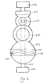
- the fishing reel 10 shown in Figure 1 comprises a main body 12, a suspension leg 14 extending upwardly from the main body, a mounting foot 16 extending transversely of the leg 14 at an upper end thereof in an intended forward/rearward direction, a generally U-shaped rotor 18 mounted on an intended front end of the body 12 with its limbs 20 and 22 directed forwardly, a spool 24 mounted on the body 12 between the arms of the rotor 18, a line clip 26 secured to the spool 24, a bail 28 having respective ends pivoted to the forward ends of the limbs 20 and 22 respectively, and a line guide 30 arranged between one end of the bail 28 and its associated limb 22.
- a double-ended winding handle 32 is attached via a winding shaft housing 34 to one side of the main body 12 of the fishing reel 10.
- the various parts of the fishing reel 10 may be made of an appropriately hard synthetic plastics material, or out of metal, stamp or die cast.
- the bail 28 and with it the line guide 30 are pivotable about the ends of the limbs 20 and 22 between a line-guiding position as illustrated in Figure 1, in which the line is guided onto the spool 24, and a line-release position, in which the bail 28 is rotated 180° about the ends of the limbs 20 and 22, relative to the position shown in Figure 1, to take the bail 28 and the guide 30 out of the way of the line.
- the plane of the line guide 30 is generally parallel with the axis of the spool 24, and the bail 28 extends around the spool 24.
- a shaft 210 which is within the housing 34 and which is fixed to the handle 32 is coupled by a bevelled gear to a portion 212 of the rotor 18 so that rotation of the handle 32 about the axis of the shaft 210 causes rotation of the rotor 18 about an axis which is at right angles to that of the shaft 210 and which extends in a forwardly direction.
- a spool shaft 224 extends along this latter axis and is inhibited from rotation about that axis by bearings 226 and 228.
- the shaft 210 is also coupled via a gear train 230 to rotate a gear wheel 232 having a spigot 234 protruding outwardly from one of its sides at right angles to the axis of the spool shaft 224.
- a block 236 secured to the spool shaft 224 is formed with a slot 238 which extends generally transversely of the axis of the spool shaft 224, has a shallow S-shape, and is engaged by the spigot 234 so that rotation of the handle shaft 210 causes rotation of the rotor 18 and simultaneous reciprocation of the spool shaft 224 along its axis and with it the spool 24.
- the gear train 230 is such as to provide twenty-four rotations of the rotor 18 per inch (2.54cm) of movement of the spool 24.
- the spool comprises a cylindrical portion 310 on to which fishing line (not shown) is wound when the fishing reel 10 is in use, respective circular flange portions 312 and 314 which are at respective opposite ends of the cylindrical portions 310, which are integral therewith, and which extend outwardly therefrom, and a cylindrical skirt portion 316 extending in an intended rearward direction from the intended rearward flange 312.
- the diameter of the spool is substantially 60mm and the depth of each of its flanges is about 28mm.
- a sleeve 318 is coaxial with the shaft 224 and forms a close fit therewith, at least a portion of the sleeve 318 having an internal hexagonal cross-section which receives as a tight fit a hexagonal cross-sectioned portion of the shaft 224.
- the sleeve 318 extends through the whole length of the cylindrical portion 310 of the spool 24 and therebeyond at both ends. At an intended rearward end, it terminates with an integrally formed circular flange 320.
- the diameter of the flange 320 is a little less than that of the skirt 316 and is considerably greater than the cross-sectional diameter of the cylindrical portion 310.
- Circular PTFE friction plates 322 are inserted and sandwiched between the flange 320 secured to a shaft 224 and the flange 312 of the spool 24.
- the diameter of the flange 320 is substantially 50mm.
- the flange 320 is formed all the way around its outer periphery with teeth 324. The teeth are uniformly spaced around the periphery and there are one hundred and fifty of them. Each has opposite side faces at an angle of 30° to one another.
- the forward flange 314 is formed with a recess in its forward side which accommodates a rotatable flange 326.
- the latter is formed with ridges on its outer face 328 to enable it to be manually rotated and is formed with an internal screw thread 330 which engages an external screw threading of the sleeve 318 so as to be able to be rotated to clamp the spool flanges 312 and 314 between the flanges 320 and 326 by an adjustable amount.
- Further circular PTFE friction plates 322 are inserted and sandwiched between the flange 326 on the shaft via the sleeve 318, and the flange 314 of the spool 24.
- the frictional characteristics of the screw thread 320 and those of the surfaces between the flange 326 and the flange 314 are such as to ensure a sliding between the friction plates 322 rather than an unscrewing of the flange 326 from the sleeve 318.
- a nylon locking device (not shown) could be used to ensure that there is no unscrewing.
- Teflon seal roller bearings 332 are arranged between the inside of the cylindrical portion 310 of the spool 24 and the outside of the sleeve 318, to facilitate smooth rotation of the spool 24 about the spool shaft 224.
- the clutch mechanism shown in Figure 3 comes into effect.
- the line may only be played out by rotation of the spool 24 to feed out the fishing line via the guide 30, with the clutch construction shown in Figure 3 acting as a drag.
- slack may be taken up by rotation of the handle 32 so that the line is retrieved and laid down on the cylindrical portion 310 of the spool 24 as already described herein.
- the clutch arrangement as shown in Figure 3 ensures a uniform action of the clutch which can be adjusted with precision and which at the same time does not result in wobble of the reel 24 on the shaft 224 which could adversely affect the laying of the line on the spool.
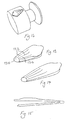
- the line guide 30 has a construction which is shown in greater detail in Figures 4 to 7.
- it comprises a first flange member 410, to which one end of the bail 28 is attached, and which has an inner planar face 412, from which a spigot 414 projects.
- the line guide 30 has a further flange member 416.
- a generally flat triangular guide member or element 418 is held between the two flange portions 410 and 416 by means of a bolt 420 which extends through holes formed in the centres of both flange portions 410 and 416, as well as the guide element 418.
- the guide element 418 is formed with three blind or through-holes 422 in a fixing flange of the element 418 located towards the three apices of the triangular form of the element 418.
- the spigot 414 may be inserted in or through any selected one of these blind or through-holes 422.
- the guide element 418 is formed with a groove 424 around its outer periphery and the surface of the bottom of the groove progressing in a direction around the element 418 has respective different radii of curvature at the three sides of the triangular form of the element 418.
- the guide element 418 has been described with only three index positions offering one of only three possible radii of curvature of the groove 424 to the line, it would be possible for a different number of indexing positions to be selected to enable any one of a corresponding number of curved surfaces to be offered to the line.
- Figure 8 shows a side view of a guide element having eight possible rotary positions.
- the base of the groove 424 would need to provide eight different curved surfaces, each of which peaks at respective different distances from the centre of the guide element. It is not necessary in this case for the radii of curvature at the peaks to vary. What is essential is that the distance of the line from the centre of the guide element where it ceases to contact that element on its way to the spool is at a different distance from the centre of the element for each peak. This applies equally to the element 418 shown in Figure 4 as it does to the element shown in Figure 8.
- the line clip 26 is shown in greater detail in Figures 9 to 12. This clip enables a set length of line to be cast, to enable the angler to drop the hook and weight at a particular location in the waters he is fishing. Thus, if by trial and error he is able to find the desired location for the hook and weight, he may secure that portion of the line where it leaves contact with the spool 24, or where it leaves contact with other portions of the line which have been laid on the spool 24, and secure it to the casting clip 26. He may then wind the line back on to the spool 24 so that upon a subsequent casting, the line will unwind itself from the spool 24 as far as the portion of line which is held by the clip 26.
- the clip 26 shown in Figures 9 to 12 comprises a first limb 910 and a second limb 912 pivoted to the first part 910 by a relatively narrow bridging portion 914 linking the two limbs 910 and 912.
- the limbs 910 and 912 are generally flat and elongate, and are integrally moulded out of a synthetic plastics material.
- the clip 26 When the clip 26 is in its closed condition, the limb 912 lies flat on top of the limb 910, which is therefore obscured from view.
- Both limbs at their ends further from the pivot 914 are widened so that each limb has a generally keyhole shape in outline.
- the lower limb 910 is formed with a through-hole at its end further from the pivot 914 to enable it to be secured to a protuberance on the outside of a skirt 316 in the spool 24.
- the clip 26 is recessed in the skirt 316 and does not protrude above the cylindrical portion of the spool 24. This ensures that it does not interfere with the winding of the line onto the spool 24, neither does it cause the line to be caught or snagged.
- the ends of the limbs 910 and 912 further from the pivot 914 have interengaging formations which enable that end of the limb 912 to be snap-fitted on to the corresponding end of the limb 910.
- the pivot end 914 of the clip 26 when it is in the closed position, as shown in Figure 9, is located on the edge of the skirt 316 where it meets the flange 312 of the spool 24.
- the neoprene material of the clip 26 enables it to stretch as shown in Figure 12 so as to reduce the shock experienced by both the line, the clip, and the fishing reel, and reduce the likelihood of damage being done to any of them.
- the clip has broadly the same construction as the embodiment shown in Figures 9 to 12, except that the pivot portion 1310 comprises a different material, such as a hard synthetic plastics material or a metal material, whilst the remainder of the clip comprises a rubber or rubber-like material. Furthermore, the clip flares in the direction from the pivot portion 1310 and is formed with strengthening ribs 1312 on the outer side of the upper limb 1314. Lastly, a lip 1316 is formed on the far end of the upper limb further from the pivot portion 1310, to enable the upper limb 1314 to be lifted more easily by a thumb.
- the pivot portion 1310 comprises a different material, such as a hard synthetic plastics material or a metal material
- the clip flares in the direction from the pivot portion 1310 and is formed with strengthening ribs 1312 on the outer side of the upper limb 1314.
- a lip 1316 is formed on the far end of the upper limb further from the pivot portion 1310, to enable the upper limb 1314 to be lifted more easily by a thumb.
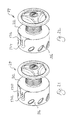
- FIG. 17 to 20 An entirely different embodiment of line clip of the present invention is shown in Figures 17 to 20. It comprises two studs 1710 and 1712. The former is secured in a hole 1714 formed in the skirt 316 of the spool 24, as shown more clearly in Figure 22. The other stud 1712 is held in a slot 1716 formed in the skirt 316 of the spool 24. The slot is positioned more closely to the flange 312 than the hole 1714, and is arranged to extend perpendicularly to the flange 312 in line with the hole 1714.
- Each stud 1710 and 1712 extends right the way through the skirt 316, and on the underside of the skirt each is formed with a respective grooved guide 1718 and 1720 around which extends an elastic O-ring 1722.
- a compression spring 1724 is located between two washers 1726 and 1728 so as to urge the latter away from one another, one of the washers 1726 resting against the inside surface of the skirt 316, and the other of the washers 1728 resting against the guide 1720 of the stud 1712.
- fishing line (not shown in Figures 17 to 20) may be guided around the stud 1712 and underneath the head 1730 thereof so that it is pinched between that head and the skirt 316.
- fishing line may be guided around the stud 1712 and underneath the head 1730 thereof so that it is pinched between that head and the skirt 316.
- the desired amount of line has unwound itself from the spool 24, it tugs on the stud 1712 which is able to move towards the flange 312 against the resilient restoring force of the O-ring 1722. This softens the shock experienced by the line, the clip and the fishing reel to reduce the likelihood of damage being done to any of them.
- Figure 20 shows how the component parts of the stud 1712 are assembled and secured to the skirt 316, by virtue of an interengaging screw-threaded shank 1732 extending from the head 1730 and an internally screw-threaded hole 1734 in the guide 1720.
- More friction plates can be positioned adjacent to the front flange of the spool 24, or alternatively more friction plates can be placed adjacent to the rear flange of the spool, than the other flange of the spool. This shifts the spool slightly to a different position along the shaft. It may be used to adjust the lay between coning and a flat line lay.
- Such adjustments of the clutch mechanism can be retained in respective different spools for respective styles of fishing, so that the user can select the spool ready-adjusted for the style of fishing he is about to commence. In addition or in the alternative, such adjustments can be used to adapt the reel to different thicknesses or different strengths of line.
Landscapes
- Life Sciences & Earth Sciences (AREA)
- Environmental Sciences (AREA)
- Animal Husbandry (AREA)
- Biodiversity & Conservation Biology (AREA)
- Storage Of Web-Like Or Filamentary Materials (AREA)
Applications Claiming Priority (2)
| Application Number | Priority Date | Filing Date | Title |
|---|---|---|---|
| GB0409148 | 2004-04-23 | ||
| GB0409148A GB0409148D0 (en) | 2004-04-23 | 2004-04-23 | Fishing reel |
Publications (2)
| Publication Number | Publication Date |
|---|---|
| EP1588614A2 true EP1588614A2 (fr) | 2005-10-26 |
| EP1588614A3 EP1588614A3 (fr) | 2006-02-15 |
Family
ID=32344333
Family Applications (1)
| Application Number | Title | Priority Date | Filing Date |
|---|---|---|---|
| EP05252424A Withdrawn EP1588614A3 (fr) | 2004-04-23 | 2005-04-19 | Moulinet de pêche |
Country Status (2)
| Country | Link |
|---|---|
| EP (1) | EP1588614A3 (fr) |
| GB (1) | GB0409148D0 (fr) |
Cited By (9)
| Publication number | Priority date | Publication date | Assignee | Title |
|---|---|---|---|---|
| GB2454519A (en) * | 2007-11-10 | 2009-05-13 | Christopher Woolley | Fishing reel |
| EP2767162A1 (fr) * | 2013-02-18 | 2014-08-20 | Shimano Components (Malaysia) SDN BHD | Pince de ligne de bobine de filage et bobine de filage l'utilisant |
| AT514425B1 (de) * | 2014-02-18 | 2015-01-15 | Hannes Sommer | Spule zur Verwendung im Angelsport |
| EP2829174A1 (fr) * | 2013-07-26 | 2015-01-28 | Shimano Inc. | Pince de ligne et bobine de moulinet de pêche sur lequel la pince est montée |
| KR20150012997A (ko) * | 2013-07-26 | 2015-02-04 | 가부시키가이샤 시마노 | 줄 계지구 및 줄 계지구가 장착된 스피닝 릴의 스풀 |
| WO2016128697A1 (fr) * | 2015-02-11 | 2016-08-18 | Spotonfish Ltd | Dispositif de mesure de ligne de pêche |
| CN106172287A (zh) * | 2016-09-27 | 2016-12-07 | 宁波市北仑海伯精密机械制造有限公司 | 一种鱼线轮的导线环组件 |
| CN111141516A (zh) * | 2018-11-01 | 2020-05-12 | 株式会社岛野 | 抛掷评价装置以及抛掷评价程序 |
| US11452285B2 (en) * | 2020-11-19 | 2022-09-27 | Yifan Xu | Positioning and line clamping device capable of realizing buffering |
Family Cites Families (8)
| Publication number | Priority date | Publication date | Assignee | Title |
|---|---|---|---|---|
| FR900325A (fr) * | 1943-07-30 | 1945-06-26 | Pezon & Michel Ets | Dispositif d'immobilisation du fil de ligne pour moulinets de pêche |
| FR2565067B1 (fr) * | 1984-06-01 | 1987-03-20 | Mitchell Sports | Dispositif d'accrochage du fil pour moulinet de peche |
| US5201477A (en) * | 1989-04-11 | 1993-04-13 | Shimano, Inc. | Spinning reel with drag brake mechanism and clutch |
| US5120001A (en) * | 1989-07-07 | 1992-06-09 | Daiwa Seiko Inc. | Fishing reel with drag mechanism |
| US5040743A (en) * | 1990-04-16 | 1991-08-20 | Zebco Corporation | Spinning reel with rear-actuated front drag |
| JP3287389B2 (ja) * | 1997-01-31 | 2002-06-04 | ダイワ精工株式会社 | 魚釣用スピニングリール |
| TW534795B (en) * | 2001-05-18 | 2003-06-01 | Shimano Kk | Spinning-reel spool |
| AU2002353100A1 (en) * | 2001-12-10 | 2003-07-09 | Better Fishtrap, Inc. | Methods and apparatus for a quick-change spool system |
-
2004
- 2004-04-23 GB GB0409148A patent/GB0409148D0/en not_active Ceased
-
2005
- 2005-04-19 EP EP05252424A patent/EP1588614A3/fr not_active Withdrawn
Non-Patent Citations (1)
| Title |
|---|
| None * |
Cited By (19)
| Publication number | Priority date | Publication date | Assignee | Title |
|---|---|---|---|---|
| GB2454519A (en) * | 2007-11-10 | 2009-05-13 | Christopher Woolley | Fishing reel |
| EP2767162A1 (fr) * | 2013-02-18 | 2014-08-20 | Shimano Components (Malaysia) SDN BHD | Pince de ligne de bobine de filage et bobine de filage l'utilisant |
| CN103988818A (zh) * | 2013-02-18 | 2014-08-20 | 株式会社岛野马来西亚配件厂有限公司 | 纺车式绕线轮的线卡定件及使用该线卡定件的纺车式绕线轮的卷筒 |
| US20140231569A1 (en) * | 2013-02-18 | 2014-08-21 | Shimano Components (Malaysia) Sdn. Bhd. | Spinning reel line clip and spinning reel spool using the same |
| KR20140103819A (ko) * | 2013-02-18 | 2014-08-27 | 시마노 컴포넌츠 (말레이지아) 에스디엔. 비에이치디. | 스피닝 릴의 줄 계지구 및 그것을 이용한 스피닝 릴의 스풀 |
| JP2014155469A (ja) * | 2013-02-18 | 2014-08-28 | Shimano Components Malaysia Sdn Bhd | スピニングリールの糸係止具及びそれを用いたスピニングリールのスプール |
| CN103988818B (zh) * | 2013-02-18 | 2018-11-13 | 株式会社岛野马来西亚配件厂有限公司 | 纺车式绕线轮的线卡定件及使用该线卡定件的纺车式绕线轮的卷筒 |
| US9210919B2 (en) * | 2013-02-18 | 2015-12-15 | Shimano Components (Malaysia) SDN, BHD | Spinning reel line clip and spinning reel spool using the same |
| EP2829174A1 (fr) * | 2013-07-26 | 2015-01-28 | Shimano Inc. | Pince de ligne et bobine de moulinet de pêche sur lequel la pince est montée |
| KR20150012997A (ko) * | 2013-07-26 | 2015-02-04 | 가부시키가이샤 시마노 | 줄 계지구 및 줄 계지구가 장착된 스피닝 릴의 스풀 |
| JP2015023837A (ja) * | 2013-07-26 | 2015-02-05 | 株式会社シマノ | 糸係止具及び糸係止具が装着されたスピニングリールのスプール |
| AT514425A4 (de) * | 2014-02-18 | 2015-01-15 | Hannes Sommer | Spule zur Verwendung im Angelsport |
| AT514425B1 (de) * | 2014-02-18 | 2015-01-15 | Hannes Sommer | Spule zur Verwendung im Angelsport |
| WO2016128697A1 (fr) * | 2015-02-11 | 2016-08-18 | Spotonfish Ltd | Dispositif de mesure de ligne de pêche |
| CN106172287A (zh) * | 2016-09-27 | 2016-12-07 | 宁波市北仑海伯精密机械制造有限公司 | 一种鱼线轮的导线环组件 |
| CN106172287B (zh) * | 2016-09-27 | 2021-12-24 | 宁波海伯集团有限公司 | 一种鱼线轮的导线环组件 |
| CN111141516A (zh) * | 2018-11-01 | 2020-05-12 | 株式会社岛野 | 抛掷评价装置以及抛掷评价程序 |
| CN111141516B (zh) * | 2018-11-01 | 2024-03-19 | 株式会社岛野 | 抛掷评价装置以及抛掷评价方法 |
| US11452285B2 (en) * | 2020-11-19 | 2022-09-27 | Yifan Xu | Positioning and line clamping device capable of realizing buffering |
Also Published As
| Publication number | Publication date |
|---|---|
| EP1588614A3 (fr) | 2006-02-15 |
| GB0409148D0 (en) | 2004-05-26 |
Similar Documents
| Publication | Publication Date | Title |
|---|---|---|
| US5400542A (en) | Fishing lure system with flexible support rod | |
| EP1588614A2 (fr) | Moulinet de pêche | |
| CA2476535C (fr) | Flasheur pour la peche | |
| US20070278335A1 (en) | Fixed spool fishing reel | |
| US20090179100A1 (en) | Dual line fly fishing reel | |
| US2810982A (en) | Mechanical line release for spinning reel | |
| US6971601B2 (en) | Spinning reel sound producing mechanism | |
| US7188795B2 (en) | Fishing reel | |
| US8302343B2 (en) | Fish strike indicator | |
| US6908054B1 (en) | Internally adjustable brake for baitcast reel | |
| KR102762281B1 (ko) | 훅 키퍼 및 낚시용 릴 | |
| US12419291B1 (en) | Spinning type fishing reel with bi-directionally rotating rotor and drag control to prevent line twist | |
| US6651916B2 (en) | Spinning-reel bail-tripping device | |
| US20060096153A1 (en) | Flexible segment fishing pole | |
| US20070033855A1 (en) | Flexible segment fishing pole | |
| AU2002216480B2 (en) | Fishing reel | |
| JP2005000104A (ja) | スピニングリールのロータ制動装置 | |
| KR101346721B1 (ko) | 낚시용 릴 | |
| JP3759576B2 (ja) | スピニングリールのベール反転装置 | |
| AU2002216480A1 (en) | Fishing reel | |
| JP3980483B2 (ja) | 固定巻き枠釣りリール | |
| KR20010067198A (ko) | 비대칭으로 결합된 스피닝릴 및 스템 | |
| US20030168540A1 (en) | Split guide device for double bearing fishing reel | |
| JP2003310113A (ja) | スピニングリールのロータ制動装置 | |
| JP2002051675A5 (fr) |
Legal Events
| Date | Code | Title | Description |
|---|---|---|---|
| PUAI | Public reference made under article 153(3) epc to a published international application that has entered the european phase |
Free format text: ORIGINAL CODE: 0009012 |
|
| AK | Designated contracting states |
Kind code of ref document: A2 Designated state(s): AT BE BG CH CY CZ DE DK EE ES FI FR GB GR HU IE IS IT LI LT LU MC NL PL PT RO SE SI SK TR |
|
| AX | Request for extension of the european patent |
Extension state: AL BA HR LV MK YU |
|
| PUAL | Search report despatched |
Free format text: ORIGINAL CODE: 0009013 |
|
| AK | Designated contracting states |
Kind code of ref document: A3 Designated state(s): AT BE BG CH CY CZ DE DK EE ES FI FR GB GR HU IE IS IT LI LT LU MC NL PL PT RO SE SI SK TR |
|
| AX | Request for extension of the european patent |
Extension state: AL BA HR LV MK YU |
|
| 17P | Request for examination filed |
Effective date: 20060814 |
|
| AKX | Designation fees paid |
Designated state(s): AT BE BG CH CY CZ DE DK EE ES FI FR GB GR HU IE IS IT LI LT LU MC NL PL PT RO SE SI SK TR |
|
| 17Q | First examination report despatched |
Effective date: 20061027 |
|
| STAA | Information on the status of an ep patent application or granted ep patent |
Free format text: STATUS: THE APPLICATION IS DEEMED TO BE WITHDRAWN |
|
| 18D | Application deemed to be withdrawn |
Effective date: 20070307 |