EP1588622A1 - Dispositif et méthode pour inciser la région anale de la carcasse d'un animal - Google Patents
Dispositif et méthode pour inciser la région anale de la carcasse d'un animal Download PDFInfo
- Publication number
- EP1588622A1 EP1588622A1 EP05075975A EP05075975A EP1588622A1 EP 1588622 A1 EP1588622 A1 EP 1588622A1 EP 05075975 A EP05075975 A EP 05075975A EP 05075975 A EP05075975 A EP 05075975A EP 1588622 A1 EP1588622 A1 EP 1588622A1
- Authority
- EP
- European Patent Office
- Prior art keywords
- vent
- centring pin
- carcass
- hollow cylinder
- blade
- Prior art date
- Legal status (The legal status is an assumption and is not a legal conclusion. Google has not performed a legal analysis and makes no representation as to the accuracy of the status listed.)
- Granted
Links
Images




Classifications
-
- A—HUMAN NECESSITIES
- A22—BUTCHERING; MEAT TREATMENT; PROCESSING POULTRY OR FISH
- A22C—PROCESSING MEAT, POULTRY, OR FISH
- A22C21/00—Processing poultry
- A22C21/06—Eviscerating devices for poultry
-
- A—HUMAN NECESSITIES
- A22—BUTCHERING; MEAT TREATMENT; PROCESSING POULTRY OR FISH
- A22B—SLAUGHTERING
- A22B5/00—Accessories for use during or after slaughtering
- A22B5/0094—Cutting or blocking the rectum of a carcass, e.g. for avoiding fecal contamination
Definitions
- the invention relates to a device and method for cutting a vent loose from a carcass, particularly a carcass of slaughtered poultry.
- vent cutters are also called vent cutters and operate in cooperation with means for keeping the carcass in the correct position for the vent cutter.
- the known devices For cutting loose the vent from the carcass the known devices usually use a hollow cylindrical blade having a cutting edge at its distal end and positioned within it a centring pin extending parallel to the centre line of the blade.
- the latter means usually comprise an overhead conveyor having trolleys provided with leg shackles, from which the carcasses hanging down are passed along a set-up with vent cutters.
- the centring pin In the process of cutting the vent loose first the centring pin is moved downwards into the vent opening of the carcass. Said centring pin can be moved up and down in axial direction within the hollow cylindrical blade, so that initially, during centring using the centring pin, the blade can still be held above the vent. After the centring pin has been urged sufficiently far into the rectum that is contiguous to the vent opening, the drive of the cylindrical blade is activated and the blade is moved downwards to cut the vent around the orbicular muscle loose from the area of the skin of the carcass beyond it. The blade then moves axially to near or over the distal end of the centring pin.
- the orbicular muscle area is subsequently retained in the vent cutter and the vent can be pulled upwards out of the carcass by retracting the vent cutter, wherein the rectum is pulled along and/or stretched a way. Then the vent cutter is operated to release the vent and rectum, after which they remain outside of the carcass.
- the known devices for instance use a centring pin provided with a helical rib.
- Said helical rib effects that the orbicular muscle during rotation of the centring pin is pulled slightly upwards in the direction of the blade.
- the vent area is retained by the rib.
- a drawback of this construction is that the vent area may slide from the rib.
- the vent that has been cut loose will not end up in the correct place, which may cause failures, at least in further treatment steps.
- dirt may escape from the vent or be taken along by the rib, due to which the carcass and/or the device may get contaminated.
- the centring pin is provided with a truncated conical thickened end, behind which the orbicular muscle - after insertion of the centring pin into the vent - is placed.
- the thickened head is provided with bores for retaining pins placed axially and around the centring pin and positioned within the blade.
- the retaining pins are moved in axial direction towards the thickened head.
- the orbicular muscle is thereby punctured and the vent is thus retained at the centring pin after which the vent can be removed.
- a drawback of puncturing the orbicular muscle by the retaining pins is that said perforation may rupture, due to which dirt may escape from the vent, as a result of which the carcass and/or the device may get contaminated.
- the invention provides a device for cutting a vent loose from a carcass, comprising a hollow cylindrical blade having a cutting edge at its distal end for cutting the vent loose, a centring pin positioned within it, and extending parallel to the centre line of the blade, driving means for rotatingly driving the blade, and clamping means which are substantially radially movable with respect to the centring pin for clamping an orbicular muscle area of the vent or an intestinal section thereof.
- the rectum of the carcass is loaded in axial direction for clamping the orbicular muscle, on the one hand due to the helical motion of the centring pin with helical rib, on the other hand due to moving the centring pin upward for puncturing the orbicular muscle with the retaining pins.
- Said axial load may cause several problems.
- the orbicular muscle may slide from the centring pin due to said axial load, after which the vent and rectum cannot be placed outside of the carcass.
- the orbicular muscle area or the rectum may rupture, as a result of which the carcass may be contaminated by residues of faeces that are in the rectum.
- clamping means which, for the clamping of the orbicular muscle area or the rectum, are substantially radially movable with respect to the centring pin, the said axial load of the rectum, at least during clamping, is at least largely avoided. In this way the above-mentioned problems are at least largely prevented.
- the motion carried out by the clamping means for clamping may have axial or rotational components, but is substantially radially oriented.
- said axial or rotational components of the motion of the clamping means are small or even absent and the clamping means are substantially radially or entirely radially moveable with respect to the centring pin.
- a part of the centring pin that can be disposed in the vent comprises first clamping means and a part of the blade that can be disposed in the carcass comprises second clamping means, wherein at least one of the first and second clamping means is movable in substantially radial direction for clamping the orbicular muscle area of the vent or an intestinal section thereof between said first and second clamping means.
- first clamping means are movable from a first position near the centring pin to a second position near the second clamping means.
- an inner side of the blade forms the second clamping means.
- the first clamping means are then formed at the outside of the centring pin.
- the first and second clamping means are placeable in a fixed position of rotation with respect to each other.
- the first and second clamping means are placed in a fixed position of rotation prior to activating the clamping means for clamping the orbicular muscle area of the vent or an intestinal section thereof.
- Such a rotation may namely lead to a rupture in the orbicular muscle area or the rectum, as a result of which the carcass is contaminated by residues of faeces that are in the rectum.
- At least one of the first and second clamping means comprises a hollow cylinder, which hollow cylinder is made of a resilient material, and wherein the device comprises means for moving both end planes of the hollow cylinder towards each other for the bulging thereof in radial direction.
- the bulging condition the orbicular muscle area of the vent or an intestinal section thereof can be clamped between the first and second clamping means and the rectum can be closed off.
- both end planes of the hollow cylinder are moved apart due to which the radial bulging is ended again.
- the hollow cylinder at least near a clamping surface of said clamping means, comprises an annular section having a higher flexibility than the sections of the hollow cylinder adjacent to this annular section.
- the hollow cylinder will more easily and therefore preferably deform at the annular section due to the higher flexibility thereof. Therefore said embodiment on the one hand offers the advantage that the hollow cylinder bulges more easily, due to which the force needed to move the end planes towards each other can be smaller, and on the other hand the advantage that the location of the bulging will be located in or near the annular section, as a result of which the axial position of the bulging is defined better.
- the annular section can be made of a material that is more flexible than the material of the sections of the hollow cylinder adjacent to this annular section.
- the annular section of the hollow cylinder may comprise a thinner wall thickness than the sections of the hollow cylinder adjacent to this annular section. A combination of both measures is also possible.
- the hollow cylinder at a side of the annular section facing away from the clamping surface is provided with one or more substantially annular channels.
- the wall thickness of the hollow cylinder thus is thinner than near the sections of the hollow cylinder adjacent to the annular channel.
- said channel extends in axial direction over the annular section.
- the channels are placed in axial direction divided over the annular section.
- the hollow cylinder is placed around the centring pin.
- the centring pin comprises an axial assembly comprising a central inner tube and an axially slidable outer tube surrounding it.
- the one end plane of the hollow cylinder is attached to inner tube
- the other end plane of the hollow cylinder is attached to the outer tube.
- the hollow cylinder at an inner side of the annular section of the hollow cylinder facing the centring pin, is provided with the one or more substantially annular channels.
- At least one of the first and second clamping means comprises a bellows or a balloon, wherein the bellows or balloon can be hydraulically or pneumatically pumped up for the bulging thereof in radial direction. Also in this case in the bulged condition, the orbicular muscle area of the vent or an intestinal section thereof can be clamped between the first and second clamping means and the rectum can be closed off.
- the bellows or balloon is placed around the centring pin.
- the bellows or balloon at least near a clamping surface of this clamping means comprises an annular section having a higher flexibility than the sections of the bellows or balloon adjacent to this annular section.
- this embodiment offers the advantage that the bellows or balloon bulges more easily, due to which the pressure needed for pumping up can be smaller, and on the other hand the advantage that the location of the bulging will be located in or near the annular section, as a result of which the axial position of the bulging is defined better.
- the annular section may be made of a material that is more flexible than the material of the sections of the bellows or balloon adjacent to this annular section.
- the annular section of the bellows or balloon may comprise a thinner wall thickness than the sections of the bellows or balloon adjacent to this annular section. A combination of both measures is also possible.
- the bellows or balloon at a side of the annular section facing away from the clamping surface is provided with one or more substantially annular channels.
- the wall thickness of the bellows or balloon thus is thinner than near the sections of the bellows or balloon adjacent to the annular channel.
- said channel extends in axial direction over the annular section.
- the channels are placed in axial direction divided over the annular section.
- the centring pin comprises a thickened head at a distal end thereof to be disposed in the vent for closing off the vent opening of the carcass. In this way it can largely be prevented that residues of faeces flow out of the rectum and contaminate the carcass.
- the blade and the centring pin are mutually axially displaceable.
- the invention provides a method for cutting a vent loose from a carcass, comprising at least partially disposing a centring pin in the vent, cutting the vent loose by means of a rotatingly driven hollow cylindrical blade that remotely surrounds the centring pin and has a cutting edge at a distal end thereof, wherein the centring pin extends parallel to the centre line of the blade, clamping an orbicular muscle area of the vent or an intestinal section thereof with clamping means by a radial displacement of said clamping means with respect to the centring pin.
- a part of the centring pin disposed in the vent comprises first clamping means, and a part of the cylindrical blade disposed in the carcass comprises second clamping means, wherein at least one of the first and second clamping means is displaced in radial direction for clamping the orbicular muscle area of the vent or an intestinal section thereof between said first and second clamping means.
- the invention provides an assembly for treating a carcass of slaughtered cattle, particularly slaughtered poultry, comprising a device for cutting a vent loose from the carcass as described above.
- the assembly comprises positioning means for positioning the carcass with respect to the device for cutting the vent loose, and tensioning means for at least while the vent is cut loose retaining the carcass.
- An example of such an assembly is an assembly for eviscerating slaughtered poultry.
- Such an assembly comprises a conveyor, for instance an overhead conveyor having trolleys provided with leg shackles, for conveying the carcasses past a number of treatment devices. In this case the carcasses are suspended from their legs the vent opening being oriented substantially upwards.
- the device for cutting the vent loose is placed substantially vertically and the centring pin is moved downwards from a position above the carcass to be inserted into the vent of the carcass.
- the vent with an intestinal section thereof can be removed from the carcass and the carcass can be subjected to further treatments in a device for cutting open the carcass, a device for eviscerating the carcass, etcetera.
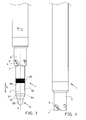
- Figure 1 shows the distal section of the vent cutter 1, particularly the distal end of a circle cylindrical blade 2 having a centre line S, and positioned coaxially within it a centring pin 3, which within certain limits is axially movable with respect to the blade 2.
- the blade 2 is rotatingly driveable in the direction A with means that are not further shown, yet which are known to the expert, whereas the centring pin 3 is placed rotation fixedly with respect to positioning and tensioning means for the carcass that are not further shown, yet which are known to the expert.
- the blade 2 has a distal end section, having a substantially circular cutting edge 4, in which a number of regularly spaced apart inclined notches 5 have been disposed.
- the notches 5 are limited all-round by cutting edges 6, wherein the cutting edge 6 is oriented diagonally in rotation direction A.
- the cutting edge 6 here forms sharp cutting teeth with the adjacent cutting edge 4.
- the centring pin 3 has a distal end section 31, with a bevelled reduced end 32, situated behind that a conically tapering transitional section 33 and situated behind that cylindrical section 34, for forming a thickened head for closing off a vent opening of the carcass.
- the distal end section 31 is placed on an axis that is concentrically surrounded by a bush 35 that is slidable along the axis in axial direction.
- the centring pin 3 furthermore comprises a hollow cylinder 36 made of resilient material, which with a first end 37 is coupled to the axis, and which a second end 38 is coupled to the bush 35. By moving both ends 37, 38 towards each other, the middle part of the hollow cylinder 36 will bulge in radial direction, that means substantially perpendicular to the centre line S.
- the distal end 31 of the centring pin 3 is passed in the direction of the vent opening of the carcass that is not further shown. It will be understood that the carcass with suitable means -known per se-will be retained in the correct position with respect to the vent cutter. Due to the spherical shape of the reduced end 32 the orbicular muscle of the vent opening is gradually urged out, so that the distal end section 31 of the centring pin 3 easily penetrates the vent opening. Further penetration is enhanced by the truncated conical surface 33, after which the orbicular muscle and the rectum are sufficiently stretched for reliably closing off the vent opening of the carcass.
- the blade 2 is moved in the direction G while being rotatingly driven in the direction A, as shown in figure 2.
- the cutting edge 4 and the teeth with cutting edge 6 then cut the vent loose from the carcass.
- the blade 2 is shown in cross-section in order to be able to show the position of the centring pin with respect to the blade 2.
- the position of the blade 2 is schematically shown.
- the entire vent cutter 1 can be pulled out of the carcass in the direction H, wherein the orbicular muscle area of the vent or an intestinal section thereof is retained between the inner surface 21 of the blade 2 and the bulged edge 40 of the hollow cylinder 36.
- the hollow cylinder 36 may over its full length have a substantially uniform wall thickness. However, preferably the hollow cylinder 36 is provided with an annular section having a wall section of greater flexibility, which considered in axial direction preferably is situated in the middle part of the hollow cylinder.
- This greater flexibility of the wall of the hollow cylinder 361, 364, 367, 370 may for instance be obtained by providing the inside of the annular section 362, 365, 368, 371 of the hollow cylinder 361, 364, 367, 370 with an annular channel 363, 366, 369, 372 as shown in the figures 6A, 6B, 6C and 6D, respectively.
- the wall of the hollow cylinder 361, 364, 367, 370 is thinner and has a greater flexibility at that location. Due to the greater flexibility of the wall of the annular section 362, 365, 368, 371 with respect to the rest of the wall of the hollow cylinder 361, 364, 367, 370 predominantly the annular section 362, 365, 368, 371 will bulge in radial direction R, as a result of which at least a part of the outside of the annular section 362, 365, 368, 371 can be operative as clamping surface for in cooperation with the inner surface 21 of the blade 2 clamping the orbicular muscle area of the vent or an intestinal section 50 thereof, as shown in figure 5.
- the maximum depth of the hollow channel 363, 366, 369, 372 is at least 25% of the wall thickness of the hollow cylinder 361, 364, 367, 370.
- the hollow cylinder 361 has a length of approximately 22 mm, an outer diameter of approximately 16 mm and the inside of the hollow cylinder 361 has an inner diameter of approximately 10 mm.
- the hollow cylinder 361 thus has a wall thickness of approximately 3 mm.
- the hollow channel 363 has a circular cross-section having a radius of curvature of 2.5 mm and a maximum depth of approximately 1 mm.
- a bellows or balloon 71 can also be placed at the location of the hollow cylinder 36, wherein the bellows or balloon 71 can be pumped up hydraulically or pneumatically for the bulging thereof in radial direction.
- a slidable bush 35 and the accompanying drive is not necessary.
- the centring pin 32, 33, 35 may simply comprise an internal channel 72 for allowing a fluid to pass through to the inside 73 of the bellows or balloon 71 for pumping it up or deflating it.
- the pressing force for clamping the orbicular muscle area between the inner surface of the blade 2 and the outer surface of the bellows or balloon 71 can be controlled by means of setting the pressure of the fluid.
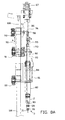
- Said vent cutter comprises a hollow blade axis 82 which at its end is provided with a blade 2.
- the blade axis 82 is placed in a blade holder block 81 so as to be rotatable about its axis.
- the blade holder block 81 is fixedly connected to a frame 100 and is provided with a guide 80. By passing the guide 80 in a first guide path (see figure 9) the position and the motion of the blade holder block 81 and therefore the blade 2 can be controlled.
- the tube 93 forms a part of the centring pin 3.
- the tube 93 is fixedly connected to a centring pin slide block 90.
- the centring pin slide block 90 is connected to the frame 100 and is movable along the frame 100 in the direction A for sliding the centring pin 3 in axial direction of the blade 2.
- the centring pin slide block 90 is provided with a guide 91. By passing the guide 91 in a second guide path the position and the motion of the centring pin slide block 90 and therefore the centring pin 3 can be controlled.
- the guide 91 of the centring pin slide block 90 can be moved with respect to the guide 80 of the blade holder block 81 and the axial position and motion of the centring pin 3 with respect to the blade 2 can be controlled.
- a drive shaft 95 for the hollow cylinder 36 has been passed through the tube 93 which drive shaft with respect to the tube 93 is slideable in axial direction B.
- the drive shaft 95 is connected to the distal end section 31 of the centring pin 3 (also see figure 4).
- the other end of the drive shaft 95 is connected to a lever 96 so as to be hinged about an axis 98.
- Said lever 96 is connected to the centring pin slide block 90 so as to be rotatable about an axis 97.
- a guide wheel 99 has been placed at an end of the lever 96 facing away form the drive shaft 95 a guide wheel 99 has been placed.
- the position and the motion of the drive shaft 95 and therefore the distal end section 31 of the centring pin 3 can be controlled via the lever 96.
- the drive shaft 95 can be axially displaced with respect to the tube 93, the axial position and motion of the distal end section 31 of the centring pin 3 with respect to the bush 35 placed at the end of the tube 93 can be controlled, and the bulging of the hollow cylinder 35 placed between the distal end section 31 of the centring pin 3 and the bush 35 can be controlled.
- the drive of the centring pin 3 is placed in line to a side of the blade axis 82 facing away from the blade 2, the drive of the blade axis 82 is shifted laterally as shown in figure 8B.
- the blade holder block 81 is provided with a drive shaft 85 for the blade 2 placed parallel to the blade axis 82.
- the blade axis 82 and the drive shaft 85 are mutually coupled by means of a gear wheel transmission, wherein the blade axis 82 is provided with a smaller toothed wheel 83 than the toothed wheel 84 of the drive shaft 85.
- a protective plate 88 has been disposed.
- the drive shaft 85 is connected to a drive pin 86 which is rotatably connected to the frame 100 and spaced apart from the blade holder block 81.
- the drive pin 86 is provided with a drive pinion or cage wheel 87 for coupling to a drive device, for instance by means of a transmission such as a toothed belt. If the vent cutter 1 is placed in an assembly for treating a carcass, wherein the assembly is provided with a conveyor device for conveying the carcasses through the assembly and wherein the vent cutter 1, at least temporarily, moves along with the conveyance direction of the carcass, said motion of the vent cutter 1 with respect to the permanent parts of the assembly can be used for driving the drive pinion 87.
- a stationary crown gear is arranged on the permanent parts of the assembly, such as for instance on the drum 61 of figure 9.
- the drive pinion 87 runs over the crown gear as a result of which the drive pinion 87 starts rotating for driving the blade 2.
- the vent cutter 1 is placed for treating substantially vertically placed carcasses, such as for instance carcasses that are suspended by their legs in leg shackles that are suspended from an overhead conveyor in the known manner.
- the treatment unit 60 is placed against a drum 61, preferably an inclined drum in the shape of a truncated circular cone, and is movable around said drum 61.
- the leg shackles (not shown) are also passed wherein the motion of the treatment unit 60 is synchronous to the motion of the leg shackles.
- the vertical orientation of the treatment unit 60 with respect to the leg shackles is obtained by passing the guides 62 in guide paths 63 disposed on the drum.
- the vent cutter 1 according to this exemplary embodiment in this case is provided with a hollow cylinder 36 made of a rubber tube material of for instance NBR 60 to 70 shore.
- the treatment unit 60 comprises a leg shackle 64 for accurately placing the carcass with respect to the vent cutter 1. After a carcass has been placed in the leg bracket 64 the brackets 65 are moved upward as a result of which the thighs of the carcass, particularly the legs of the poultry carcass, are clamped between the leg bracket 64 and the brackets 65 for positioning the carcass.
- the leg bracket 64 ensures that the carcass is centred in radial direction with respect to the vent cutter 1.
- a tail clamp (not shown) can also be placed near the leg bracket 64. Such a tail clamp presses the tail out of the path of the vent cutter 1, so that the blade 2 cannot bore into the tail.
- the vent cutter 1 is activated for inserting the centring pin 3, cutting the vent loose by means of the cylindrical blade 2, clamping the orbicular muscle area of the vent or an intestinal section thereof between the inner surface of the blade 2 and the bulged edge of the hollow cylinder 36, taking out the clamped orbicular muscle area by retracting the vent cutter 1 from the carcass, wherein the rectum is pulled along or stretched a way, and the vent cutter 1 releasing the vent and rectum, after which they remain outside the carcass for further treatment.
- the carcass can be conveyed onwards to further treatment devices. Subsequently the treatment unit 60 with the vent cutter 1 can be cleaned, after which it is ready for placing a second carcass therein. Subsequently the vent cutter 1 can repeat its operation cycle on said second carcass, and so on.
- vent cutter is placed in a substantially vertical or inclined position, it will be clear to the expert that the vent cutter according to the invention may have any desired spatial orientation.
Landscapes
- Life Sciences & Earth Sciences (AREA)
- Engineering & Computer Science (AREA)
- Food Science & Technology (AREA)
- Wood Science & Technology (AREA)
- Zoology (AREA)
- Surgical Instruments (AREA)
Applications Claiming Priority (2)
| Application Number | Priority Date | Filing Date | Title |
|---|---|---|---|
| NL1026016A NL1026016C2 (nl) | 2004-04-23 | 2004-04-23 | Inrichting en werkwijze voor het lossnijden van een aars van een karkas. |
| NL1026016 | 2004-04-23 |
Publications (2)
| Publication Number | Publication Date |
|---|---|
| EP1588622A1 true EP1588622A1 (fr) | 2005-10-26 |
| EP1588622B1 EP1588622B1 (fr) | 2007-07-11 |
Family
ID=34938214
Family Applications (1)
| Application Number | Title | Priority Date | Filing Date |
|---|---|---|---|
| EP20050075975 Expired - Lifetime EP1588622B1 (fr) | 2004-04-23 | 2005-04-25 | Dispositif et méthode pour inciser la région anale de la carcasse d'un animal |
Country Status (4)
| Country | Link |
|---|---|
| EP (1) | EP1588622B1 (fr) |
| DE (1) | DE602005001567T2 (fr) |
| DK (1) | DK1588622T3 (fr) |
| NL (1) | NL1026016C2 (fr) |
Cited By (1)
| Publication number | Priority date | Publication date | Assignee | Title |
|---|---|---|---|---|
| WO2008085049A1 (fr) | 2007-01-10 | 2008-07-17 | Systemate Group B.V. | Dispositif permettant de sectionner le cloaque de volailles abattues |
Citations (4)
| Publication number | Priority date | Publication date | Assignee | Title |
|---|---|---|---|---|
| EP0722666A1 (fr) * | 1995-01-18 | 1996-07-24 | Baader North America Corporation | Procédé et appareil pour inciser la région anale de volailles abattues |
| US5688164A (en) * | 1994-09-26 | 1997-11-18 | Commonwealth Scientific And Industrial Research Organisation | Rectum separating |
| EP0820697A2 (fr) * | 1996-07-26 | 1998-01-28 | Stork Gamco Inc. | Dispositif pour enlever l'anus maintenant le peau |
| EP0843971A2 (fr) * | 1996-11-20 | 1998-05-27 | Systemate Holland B.V. | Dispositif pour enlever et/ou ouvrir l'anus de volailles en cours d'abattage |
-
2004
- 2004-04-23 NL NL1026016A patent/NL1026016C2/nl not_active IP Right Cessation
-
2005
- 2005-04-25 EP EP20050075975 patent/EP1588622B1/fr not_active Expired - Lifetime
- 2005-04-25 DK DK05075975T patent/DK1588622T3/da active
- 2005-04-25 DE DE200560001567 patent/DE602005001567T2/de not_active Expired - Lifetime
Patent Citations (4)
| Publication number | Priority date | Publication date | Assignee | Title |
|---|---|---|---|---|
| US5688164A (en) * | 1994-09-26 | 1997-11-18 | Commonwealth Scientific And Industrial Research Organisation | Rectum separating |
| EP0722666A1 (fr) * | 1995-01-18 | 1996-07-24 | Baader North America Corporation | Procédé et appareil pour inciser la région anale de volailles abattues |
| EP0820697A2 (fr) * | 1996-07-26 | 1998-01-28 | Stork Gamco Inc. | Dispositif pour enlever l'anus maintenant le peau |
| EP0843971A2 (fr) * | 1996-11-20 | 1998-05-27 | Systemate Holland B.V. | Dispositif pour enlever et/ou ouvrir l'anus de volailles en cours d'abattage |
Cited By (2)
| Publication number | Priority date | Publication date | Assignee | Title |
|---|---|---|---|---|
| WO2008085049A1 (fr) | 2007-01-10 | 2008-07-17 | Systemate Group B.V. | Dispositif permettant de sectionner le cloaque de volailles abattues |
| NL1033199C2 (nl) | 2007-01-10 | 2008-07-18 | Systemate Group Bv | Inrichting voor het uitsnijden van de aars van slachtgevogelte. |
Also Published As
| Publication number | Publication date |
|---|---|
| DE602005001567T2 (de) | 2008-03-13 |
| DK1588622T3 (da) | 2007-11-12 |
| NL1026016C2 (nl) | 2005-10-25 |
| DE602005001567D1 (de) | 2007-08-23 |
| EP1588622B1 (fr) | 2007-07-11 |
Similar Documents
| Publication | Publication Date | Title |
|---|---|---|
| US4016624A (en) | Poultry cut-up machine | |
| US3958303A (en) | Method and apparatus for poultry vent removal | |
| CA2320774C (fr) | Procedes et appareils destines a des operations de traitement sur des animaux abattus ou sur des parties de ces animaux | |
| US5123871A (en) | Device for cutting out the vent of slaughtered poultry | |
| DK156808B (da) | Anlaeg til udtagning af indvolde af slagtede dyr | |
| DE69502271T2 (de) | Afterabtrennung | |
| DE2755475C2 (fr) | ||
| JP6212550B2 (ja) | 屠殺された動物の屠殺体を開く方法および装置 | |
| US5167568A (en) | Device and installation for selectively removing organs from a slaughtered animal | |
| US4682387A (en) | Apparatus and method for stripping casing from sausages | |
| EP3235383A1 (fr) | Dispositif pour la préparation d'un produit alimentaire en boyaux | |
| EP1588622B1 (fr) | Dispositif et méthode pour inciser la région anale de la carcasse d'un animal | |
| DK152774B (da) | Apparat til aabning af kropshulrummet i et fjerk rae | |
| EP2091337B1 (fr) | Procédé et dispositif permettant de séparer d'une carcasse l'anus et au moins une partie du rectum | |
| US8157625B2 (en) | Method and apparatus for collecting meat from an animal part | |
| JP2016015967A (ja) | 屠殺された家禽の首の内側皮膚に施される清浄化作業を実施する装置 | |
| EP2099307B1 (fr) | Dispositif permettant de sectionner le cloaque de volailles abattues | |
| EP0843971B1 (fr) | Dispositif pour enlever et/ou ouvrir l'anus de volailles en cours d'abattage | |
| IL37961A (en) | Machine and method for processing slaughtered poultry | |
| JP7669384B2 (ja) | バングホルダを備えたバング穿孔機 | |
| CN215202310U (zh) | 全自动钢丝绳去塑机 | |
| JP2024536042A (ja) | 切断装置、切断装置を含むシステム、及び動物の屠体の直腸端部を切り離す方法 | |
| US20050186895A1 (en) | Decropping tool and wrapped cam for use in food processing machinery | |
| EP2547212B1 (fr) | Procédé pour le traitement d'une partie d'un animal de boucherie et dispositif pour appliquer un tel procédé | |
| US4987642A (en) | System for cutting meat from bone |
Legal Events
| Date | Code | Title | Description |
|---|---|---|---|
| PUAI | Public reference made under article 153(3) epc to a published international application that has entered the european phase |
Free format text: ORIGINAL CODE: 0009012 |
|
| AK | Designated contracting states |
Kind code of ref document: A1 Designated state(s): AT BE BG CH CY CZ DE DK EE ES FI FR GB GR HU IE IS IT LI LT LU MC NL PL PT RO SE SI SK TR |
|
| AX | Request for extension of the european patent |
Extension state: AL BA HR LV MK YU |
|
| 17P | Request for examination filed |
Effective date: 20060330 |
|
| AKX | Designation fees paid |
Designated state(s): DE DK NL |
|
| GRAP | Despatch of communication of intention to grant a patent |
Free format text: ORIGINAL CODE: EPIDOSNIGR1 |
|
| GRAS | Grant fee paid |
Free format text: ORIGINAL CODE: EPIDOSNIGR3 |
|
| GRAA | (expected) grant |
Free format text: ORIGINAL CODE: 0009210 |
|
| AK | Designated contracting states |
Kind code of ref document: B1 Designated state(s): DE DK NL |
|
| REF | Corresponds to: |
Ref document number: 602005001567 Country of ref document: DE Date of ref document: 20070823 Kind code of ref document: P |
|
| REG | Reference to a national code |
Ref country code: DK Ref legal event code: T3 |
|
| PLBE | No opposition filed within time limit |
Free format text: ORIGINAL CODE: 0009261 |
|
| STAA | Information on the status of an ep patent application or granted ep patent |
Free format text: STATUS: NO OPPOSITION FILED WITHIN TIME LIMIT |
|
| 26N | No opposition filed |
Effective date: 20080414 |
|
| REG | Reference to a national code |
Ref country code: NL Ref legal event code: SD Effective date: 20100330 |
|
| PGFP | Annual fee paid to national office [announced via postgrant information from national office to epo] |
Ref country code: NL Payment date: 20150410 Year of fee payment: 11 |
|
| PGFP | Annual fee paid to national office [announced via postgrant information from national office to epo] |
Ref country code: DE Payment date: 20150331 Year of fee payment: 11 |
|
| PGFP | Annual fee paid to national office [announced via postgrant information from national office to epo] |
Ref country code: DK Payment date: 20160311 Year of fee payment: 12 |
|
| REG | Reference to a national code |
Ref country code: DE Ref legal event code: R119 Ref document number: 602005001567 Country of ref document: DE |
|
| REG | Reference to a national code |
Ref country code: NL Ref legal event code: MM Effective date: 20160501 |
|
| PG25 | Lapsed in a contracting state [announced via postgrant information from national office to epo] |
Ref country code: NL Free format text: LAPSE BECAUSE OF NON-PAYMENT OF DUE FEES Effective date: 20160501 Ref country code: DE Free format text: LAPSE BECAUSE OF NON-PAYMENT OF DUE FEES Effective date: 20161101 |
|
| REG | Reference to a national code |
Ref country code: DK Ref legal event code: EBP Effective date: 20170430 |
|
| PG25 | Lapsed in a contracting state [announced via postgrant information from national office to epo] |
Ref country code: DK Free format text: LAPSE BECAUSE OF NON-PAYMENT OF DUE FEES Effective date: 20170430 |