EP1588641A2 - Dispositif de fixation de l'extrémité d'une bande à un object - Google Patents
Dispositif de fixation de l'extrémité d'une bande à un object Download PDFInfo
- Publication number
- EP1588641A2 EP1588641A2 EP05450047A EP05450047A EP1588641A2 EP 1588641 A2 EP1588641 A2 EP 1588641A2 EP 05450047 A EP05450047 A EP 05450047A EP 05450047 A EP05450047 A EP 05450047A EP 1588641 A2 EP1588641 A2 EP 1588641A2
- Authority
- EP
- European Patent Office
- Prior art keywords
- band
- pin
- pin bearing
- end part
- bearing
- Prior art date
- Legal status (The legal status is an assumption and is not a legal conclusion. Google has not performed a legal analysis and makes no representation as to the accuracy of the status listed.)
- Granted
Links
Images

Classifications
-
- A—HUMAN NECESSITIES
- A44—HABERDASHERY; JEWELLERY
- A44C—PERSONAL ADORNMENTS, e.g. JEWELLERY; COINS
- A44C5/00—Bracelets; Wrist-watch straps; Fastenings for bracelets or wrist-watch straps
- A44C5/14—Bracelets; Wrist-watch straps; Fastenings for bracelets or wrist-watch straps characterised by the way of fastening to a wrist-watch or the like
-
- Y—GENERAL TAGGING OF NEW TECHNOLOGICAL DEVELOPMENTS; GENERAL TAGGING OF CROSS-SECTIONAL TECHNOLOGIES SPANNING OVER SEVERAL SECTIONS OF THE IPC; TECHNICAL SUBJECTS COVERED BY FORMER USPC CROSS-REFERENCE ART COLLECTIONS [XRACs] AND DIGESTS
- Y10—TECHNICAL SUBJECTS COVERED BY FORMER USPC
- Y10T—TECHNICAL SUBJECTS COVERED BY FORMER US CLASSIFICATION
- Y10T24/00—Buckles, buttons, clasps, etc.
- Y10T24/47—Strap-end-attaching devices
- Y10T24/4718—Watch pintle connected
-
- Y—GENERAL TAGGING OF NEW TECHNOLOGICAL DEVELOPMENTS; GENERAL TAGGING OF CROSS-SECTIONAL TECHNOLOGIES SPANNING OVER SEVERAL SECTIONS OF THE IPC; TECHNICAL SUBJECTS COVERED BY FORMER USPC CROSS-REFERENCE ART COLLECTIONS [XRACs] AND DIGESTS
- Y10—TECHNICAL SUBJECTS COVERED BY FORMER USPC
- Y10T—TECHNICAL SUBJECTS COVERED BY FORMER US CLASSIFICATION
- Y10T24/00—Buckles, buttons, clasps, etc.
- Y10T24/47—Strap-end-attaching devices
- Y10T24/4782—Watch strap
Definitions
- the invention relates to a device for connecting an end portion of a tape a rigid part, in particular a bracelet, such as a watch strap, to a housing, like a watch case, with one at the end part of the strap and arranged with his Longitudinal axis transverse to the longitudinal direction of the tape extending pin with at least one Recess of the rigid part can be brought into engagement, and a method for manufacturing a bracelet.
- the invention aims to avoid these disadvantages and difficulties and provides
- the task of creating a device of the type described above, with the one Tape to a rigid part - even if this has different shapes - attached can be, in particular one and the same band under optimal adaptation to differently designed rigid parts can be connected.
- This object is according to the invention in a device of the type described above solved by the fact that the pin opposite the tape in a direction transverse to his Longitudinal axis can be brought into different positions and in this of him opposite the tape einEnglishbaren layers on the belt is fixable.
- the invention thus takes a deviating from the prior art way it will namely, not the end member of the band to the rigid part to which it is to be attached, adapted, but according to the invention can with one and the same end part the distance be bridged between the pin and different rigid parts by the pin is brought into different positions relative to the end part of the band; that is, the Greater distance, the pen is in the end of the band further back, he is smaller, he will be put forward and just as well he can be varied in height. Therefore Is inventively preferably the pin in the longitudinal direction of the band or moved expedient also be brought in the thickness direction of the tape.
- a simple, inexpensive construction of the device, a variety different positions of the pin relative to the end portion of the tape allows is characterized in that the pin is in a parallel with its longitudinal extent can be used to pin extending pin bearing, which in turn on the band across the Adjustable longitudinal axis of the pin and in the ingestible by him layers can be fixed, wherein preferably the pin bearing has one or more recesses into which the Pen is usable. It is also possible that the pin bearing against another with a another position is exchanged for a pen.
- Another particularly favorable construction which is a variety of different Positions of the pin relative to the end portion of the tape allows is thereby characterized in that the pin is in one with its longitudinal axis parallel to the pin extending pin bearing is used, which in turn in a recess of the end portion of the Bandes used in opposite the longitudinal axis of the pin bearing different rotational positions is and that the pin bearing at least one eccentric to its longitudinal axis having Has recess for receiving the pin.
- the pin bearing expediently has a cross section over its longitudinal extent a regular polygon on and the end part of the band a corresponding one Recess for receiving the pin bearing.
- pin bearing over its longitudinal extension a cross-section of a circle, rectangle or star and the end part of the band has a corresponding recess for receiving having the pin bearing.
- the pin bearing with a cross section of a circle provided, so by turning this pin bearing relative to the end portion of the tape in the Stiftlager stored pin are very difficult to be adjusted.
- the band is at its end portion receiving the pin with a pin either picking up directly or picking up the pin via the pin bearing Reinforcement provided.
- pin is mounted asymmetrically in the pin bearing, then different layers can be of the pin over the end of the band also achieved by the pin bearing turned around the longitudinal direction of the tape in the band or in one of the band provided reinforcing member is used.
- the pin bearing on the band or on the reinforcing part of the band against the side Shifting by means of a safety device, such as a nose, a clamping screw, a cross-sectional change, etc., can be fixed.
- a safety device such as a nose, a clamping screw, a cross-sectional change, etc.
- the pin or the Pin bearing at least one screw is provided with the pin or the pin bearing opposite the tape in one at the pin bearing, at the end part of the tape or at one Reinforcing part of the tape provided slot is slidable. This applies for example, for a pin bearing with circular cross-section.
- the reinforcing member to the band, this is opposite the band fixed in a form-fitting manner according to a preferred embodiment, preferably the end part of the band or an optional reinforcing member to the shape of the rigid Part adapted, with an adjustment when the end part of the tape or a optionally provided reinforcement part of an elastically deformable material, such as rubber, plastic, in particular thermoplastic or thermoplastic Elastomers is formed, only in broad strokes, i. under disregard of any Tolerances is necessary.
- an elastically deformable material such as rubber, plastic, in particular thermoplastic or thermoplastic Elastomers
- the pin bearing is formed of a material of higher hardness and strength as the end part of the band or an optionally provided reinforcement part.
- the tape indicates Matching tape at its end part reaching from its top to the pen warehouse Opening up and is the pen bearing with lying in the opening coming and his Positions characteristic markings provided, wherein advantageously the width of the Adapter band is dimensioned smaller than the distance between the horns of a watch case.
- the production of a band designed according to the invention is effected by that at least the formation of the end part of the tape or the production of an am End part of the band provided reinforcement part by injection molding.
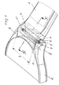
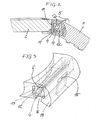
- Fig. 1 is an oblique view of an on Watch case connected band and Fig. 2 a according to the lines II - II of Figure 1 illustrate the laid section.
- Fig. 3 shows a detail of Fig. 1 also in oblique on an enlarged scale.
- Figs. 4 and 5 illustrate variants in analogous to Fig. 2 Presentation, but also enlarged.
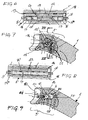
- Fig. 6 shows a section through an end portion of the Bandes and through the pin transverse to the longitudinal extent of the band.
- Figs. 7 and 9 provide further variants in Fig. 2 analog representation and Fig. 8 represents one according to the line VIII - VIII of FIG. 7 guided section.
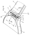
- Fig. 10 illustrates in to Fig. 1 analog Representation acting as a setting aid fitting band.
- a watch strap 1 on a watch case 2 passes through a pin 3, preferably a spring pin, a recess 4 of an end portion 5 of the Uhrarmbandes 1 and snapped with its pin-shaped ends 6 in recesses 7 of the watch case. 2 protruding noses or horns 8, between which the end part 5 of the watch strap 1 to lie down, come on.
- the width 9 of the Uhrarmbandes 1 is according to the distance of the two Measure horns 8 of the watch case 2.
- the watch case 2 facing end side 10 of the End portion 5 of the Uhrarmbandes 1 corresponds in the non-installed state approximately to Curvature having the watch case 2 between the two horns 8, namely both in the circumferential direction and in a direction perpendicular thereto.
- the watch band 1 as Plastic watch strap executed, creating a compliance through elastic behavior the plastic is given.
- Essential for the invention is that between the end part. 5 the Uhrarmbandes 1 and the watch case 2 a contact, and as possible a gap-free Contact is achieved, which is achieved as follows:
- the pin 3 is in a Recess 4 of a pin bearing 12 with the least possible clearance or used without play, as will be explained later.
- the pin bearing 12 itself has a square cross-section on and is in a corresponding to its cross-section recess 13 of a Reinforcing part 14, which is cast in the end part 5 of the Uhrarmbandes 1, used.
- to better fixation of the reinforcing member 14 at the end portion 5 of the watch band 1 has the Reinforcing member 14 a transversely to its longitudinal extent passing through recess 15th on, which is filled by the material of the watch strap during the manufacture of the watch strap and so the reinforcing member 14 against lateral displacement and tearing out of the Watch strap 1 additionally secures.
- the reinforcing member 14 itself is in the longitudinal direction of the watch band 1 entirely from Surrounding the watchband 1 material. On its underside, it has one from the outside up to the pin bearing 12 projecting recess 16, thus releasing the pin 3, for example a spring pin, i. Retraction of an end portion 3 'of the spring pin (see Fig. 6 and 8), for dismantling the watch strap 1 is possible. That's why it is Pin bearing 12 slightly shorter than the distance between the horns 8 of Watch case 2.
- the watch band 1 shown in Fig. 2 is, as mentioned, made of plastic and for example, produced by injection molding. In this case can on the Reinforcement also be waived.
- the pin bearing 12 is then directly in the end part. 5 used the watch band 1.
- the pen 3 can also directly into a Recess 4 of the end portion 5 of the plastic tape are used.
- the watch strap 1 is designed as a leather strap, it usually has on his Upper side of an upper leather and a lining leather on its side adjacent to the wrist. Between the two joined together at their edges (e.g., with a seam) Leather strips of the lining leather and the upper leather is often provided with an insert.
- the reinforcing member 14 is particularly advantageous and it is the lining leather and the upper leather at least partially entwined, wherein the lining leather with the Upper leather approximately at the height of half of the watch case 2 facing side of the Reinforcement parts 14 connected, for example, is glued.
- the reinforcing member 14th wraps around and is connected at the bottom with the lining leather.
- the reinforcing member 14 has the purpose of adaptability to that between the horns 8 given shape of the watch case 1 on a certain deformability, for example may be given by an elasticity of this part 14. Is this reinforcing member 14 is not present, for example, when the entire watch band 1 is made in one piece, the tape end 5 itself has this adaptability.
- the recess 4 for the pin 3 is in the pin bearing 12 off-center and preferably also arranged asymmetrically.
- the recesses 4 for the pin 3 are two recesses 4, 4 'are provided for the pin 3, which, however, merge into one another.
- a the recesses 4 lies with its longitudinal axis 17 at a diagonal of the cross section of the Pin bearing 12, the other recess 4 'is with its longitudinal axis 17' completely asymmetrical and at a different radial distance from the longitudinal axis 18 of the pin bearing 12 than the other recess 4.
- FIG. 4 illustrates the different positions of the longitudinal axis 17 of the recess 4 for the pin 3, which can be achieved if a single recess 4 in the pin bearing 12th is provided asymmetrically. In Fig. 5, this is intended for two in the pin bearing 12 Recesses 4, 4 'illustrated.
- the pin 3 is formed in two parts and each of the two parts 3 "and 3" ' inserted in a separate recess 4 ', 4 "of the pin bearing 12, which recesses 4', 4" are aligned with each other.
- the pin bearing 12 is preferably in the recess of the reinforcing member 14 with a Press fit inserted; to secure the position along its longitudinal axis 18 can
- additional locking lugs 19 may be provided which a certain snapping the Pin bearing 12 in the reinforcement member 14 cause when these locking lugs 19 in corresponding recesses 20 after the positioning of the pin bearing 12th engage.
- the pin bearing 12 has a different cross-sectional shape than a for example, it would be possible to choose a shape of an equilateral one Triangle to choose or even a rectangular shape or a circular cross section, such as the latter is illustrated, for example, in FIGS. 7 and 8.
- a locking screw 21 is provided, for example, in a threaded hole 22 of the Reinforcement 14 is screwed and in an approximately midway the longitudinal extent of the Pin bearing 12 provided peripheral groove 23 engages, thereby simultaneously the location of the pin bearing 12 is fixed in the direction of its longitudinal axis 18.
- To twist the Pin bearing 12 is a lateral approach 12 "or a groove on an end face of the pin bearing 12th
- a further variant is shown, according to the pin bearing 12 in a Recess 13 'of the reinforcing member 14, which is approximately in the longitudinal direction of the end part 5 of the watch strap 1 or in a plane of the watch case 2 extends, displaceable guided, in the plane of the watch case 2.
- an adjusting device such as two at a distance from each other adjusting screws 24
- the recess 4 may be off-center of the pin bearing 12, whereby the pin bearing 12 can be used in the inverted position and thus more Positions of the pin 3 relative to the watch case 1 allows.
- the invention can be realized on different watch bands 1, for example, also on multilayered and also on leather bracelets; as well Steel bracelets, for example, formed by articulated link bodies are.
- a so-called fitting tape 1 ' is shown, which serves as an adjustment aid for finding the correct position of the pin 3 in a watch strap 1 is used.
- This fitting band 1 ' the from the inside, i. with respect to the pin bearing 12 is identical to that in Fig. 1st shown Uhrarmband 3, has at its upper side on the end part 5 an opening 26 which extends to the recess 13 for the pin bearing 12 so that from the top a partial view on the pin bearing 12 is possible.
- the pin bearing 12 itself has at the periphery markings 27, for example, numbers of "1" to "8", wherein each one digit is attached to a peripheral side such that at inserted pin bearing 12 is a figure through the recess 26 can be seen.
- the numbers 1 to 4 stand for the pin bearing 12 in a first position and the numbers 5 to 8 for the Pin bearing in the inverted position (turned around the longitudinal direction of the fitting band 1 '). For this reason, the opening 26 is not centered on the width of the fitting band 1 ' arranged, but moved closer to a band edge area.
- the matching band 1 'expediently has a width 9', which is dimensioned somewhat smaller than the distance between the horns 8 of the watch case 2, so that the correct engagement of the Pin 3, i. its end parts 3 'in the recesses 7, can be checked.
- the invention is also applicable to bands other than watch straps that are attached to a rigid part be mounted, for example, for a mobile phone, a player for a music store etc.
Landscapes
- Orthopedics, Nursing, And Contraception (AREA)
- Purses, Travelling Bags, Baskets, Or Suitcases (AREA)
- Electric Clocks (AREA)
- Package Frames And Binding Bands (AREA)
Priority Applications (1)
| Application Number | Priority Date | Filing Date | Title |
|---|---|---|---|
| PL05450047T PL1588641T3 (pl) | 2004-04-22 | 2005-03-15 | Urządzenie do przyłączania części końcowej paska do części nieruchomej |
Applications Claiming Priority (2)
| Application Number | Priority Date | Filing Date | Title |
|---|---|---|---|
| AT3042004 | 2004-04-22 | ||
| AT0030404U AT7595U1 (de) | 2004-04-22 | 2004-04-22 | Vorrichtung zum anschluss eines endteiles eines bandes an einen standteil |
Publications (3)
| Publication Number | Publication Date |
|---|---|
| EP1588641A2 true EP1588641A2 (fr) | 2005-10-26 |
| EP1588641A3 EP1588641A3 (fr) | 2006-06-07 |
| EP1588641B1 EP1588641B1 (fr) | 2011-03-09 |
Family
ID=34427243
Family Applications (1)
| Application Number | Title | Priority Date | Filing Date |
|---|---|---|---|
| EP05450047A Expired - Lifetime EP1588641B1 (fr) | 2004-04-22 | 2005-03-15 | Dispositif de fixation de l'extrémité d'une bande à un object |
Country Status (6)
| Country | Link |
|---|---|
| US (1) | US7451528B2 (fr) |
| EP (1) | EP1588641B1 (fr) |
| AT (2) | AT7595U1 (fr) |
| DE (1) | DE502005011064D1 (fr) |
| DK (1) | DK1588641T3 (fr) |
| PL (1) | PL1588641T3 (fr) |
Families Citing this family (16)
| Publication number | Priority date | Publication date | Assignee | Title |
|---|---|---|---|---|
| EP1800559B1 (fr) * | 2005-12-23 | 2008-10-08 | The Swatch Group Management Services AG | Lien comportant un carter de fixation formé d'une plaque et d'une contre-plaque |
| EP2579107B1 (fr) * | 2011-10-05 | 2020-09-02 | Suunto Oy | Boîtier de montre et dispositif de montre-bracelet |
| US8770831B1 (en) | 2012-07-19 | 2014-07-08 | Invicta Watch Company Of America, Inc. | Coupling pin connection for securing a watchband to a watchcase |
| JP2014236781A (ja) * | 2013-06-06 | 2014-12-18 | カシオ計算機株式会社 | 部材連結構造、バンド取付構造、および時計 |
| KR101782773B1 (ko) | 2013-03-15 | 2017-09-27 | 애플 인크. | 부착 장치 및 관련된 사용 및 제조 방법 |
| CH708815B1 (fr) * | 2013-11-06 | 2017-12-29 | The Swatch Group Man Services Ag | Elément d'habillage pour une carrure d'une montre-bracelet. |
| US10184506B2 (en) * | 2014-08-11 | 2019-01-22 | Apple Inc. | Captive elements of an attachment system |
| US9894964B2 (en) | 2014-08-11 | 2018-02-20 | Apple Inc. | Consumer product attachment systems having a locking assembly |
| US10085523B2 (en) | 2014-08-11 | 2018-10-02 | Apple Inc. | Attachment system for an electronic device |
| US10064460B2 (en) | 2015-09-30 | 2018-09-04 | Apple Inc. | Frictional stabilization of band and securement mechanism |
| US10219591B2 (en) | 2016-03-21 | 2019-03-05 | Apple Inc. | Attachment system for an electronic device |
| US10149518B1 (en) | 2016-08-08 | 2018-12-11 | Apple Inc. | Clasp assembly for a wearable device |
| CN110623642B (zh) * | 2019-09-25 | 2022-03-29 | 歌尔科技有限公司 | 一种连接组件和具有该连接组件的穿戴设备 |
| US20210286402A1 (en) | 2020-03-13 | 2021-09-16 | Interlokit Inc. | Accessory Attachment Apparatus And Methods Related Thereto |
| USD1122137S1 (en) | 2020-03-13 | 2026-04-14 | Interlokit, Inc. | Watch band |
| CN112806678B (zh) * | 2021-01-20 | 2023-04-07 | 维沃移动通信有限公司 | 一种手表 |
Family Cites Families (16)
| Publication number | Priority date | Publication date | Assignee | Title |
|---|---|---|---|---|
| US3123882A (en) * | 1964-03-10 | Meyerson | ||
| US1784887A (en) * | 1929-10-17 | 1930-12-16 | Robert F Campbell | Wrist-watch attachment |
| US2510938A (en) * | 1949-08-27 | 1950-06-06 | Foster Metal Products Inc | Wrist watch connector |
| US2876521A (en) * | 1956-04-25 | 1959-03-10 | Legman Nathan | Watch band and clasp |
| US2948941A (en) | 1958-04-10 | 1960-08-16 | Elgin Nat Watch Co | Replaceable end links for expansion watch bands |
| CH419694A (fr) * | 1965-05-03 | 1966-08-31 | Manufacuture Genevoise De Boit | Dispositif de fixation d'une extrémité de bracelet à une montre |
| US3740804A (en) | 1971-09-15 | 1973-06-26 | Pale Corp | Watch end |
| DE2249827A1 (de) | 1972-10-11 | 1974-04-18 | Forrer Jacques | Steg fuer armbanduhrgehaeuse |
| US4217681A (en) * | 1978-12-26 | 1980-08-19 | Timex Corporation | Releasable and adjustable end attachment for watchband and the like |
| DE2950705A1 (de) * | 1979-12-17 | 1981-06-25 | Union Rheinische Braunkohlen Kraftstoff AG, 5000 Köln | Verfahren zur gewinnung von russ aus waessrigem suspensionen |
| US4419770A (en) * | 1981-05-02 | 1983-12-06 | Sony Corporation | Wrist AM radio receiver |
| JP2838865B2 (ja) | 1995-02-20 | 1998-12-16 | セイコー株式会社 | 腕時計用外装部品の結合構造 |
| US5689867A (en) * | 1996-09-30 | 1997-11-25 | Katz; Teresa | Interchangeable clasp |
| US6212414B1 (en) * | 1999-08-24 | 2001-04-03 | Motorola, Inc. | Wrist-carried radiotelephone |
| JP3559794B2 (ja) | 1999-11-30 | 2004-09-02 | 高島産業株式会社 | 時計用連結構造および時計 |
| JP2003052422A (ja) | 2001-08-20 | 2003-02-25 | Seiko Instruments Inc | ケース、バンド及び時計 |
-
2004
- 2004-04-22 AT AT0030404U patent/AT7595U1/de not_active IP Right Cessation
-
2005
- 2005-03-15 DK DK05450047.5T patent/DK1588641T3/da active
- 2005-03-15 DE DE502005011064T patent/DE502005011064D1/de not_active Expired - Lifetime
- 2005-03-15 PL PL05450047T patent/PL1588641T3/pl unknown
- 2005-03-15 EP EP05450047A patent/EP1588641B1/fr not_active Expired - Lifetime
- 2005-03-15 AT AT05450047T patent/ATE500762T1/de active
- 2005-03-18 US US11/083,200 patent/US7451528B2/en not_active Expired - Fee Related
Also Published As
| Publication number | Publication date |
|---|---|
| DK1588641T3 (da) | 2011-05-30 |
| US7451528B2 (en) | 2008-11-18 |
| US20050235464A1 (en) | 2005-10-27 |
| EP1588641B1 (fr) | 2011-03-09 |
| AT7595U1 (de) | 2005-06-27 |
| HK1084567A1 (en) | 2006-08-04 |
| EP1588641A3 (fr) | 2006-06-07 |
| DE502005011064D1 (de) | 2011-04-21 |
| PL1588641T3 (pl) | 2011-08-31 |
| ATE500762T1 (de) | 2011-03-15 |
Similar Documents
| Publication | Publication Date | Title |
|---|---|---|
| EP1588641B1 (fr) | Dispositif de fixation de l'extrémité d'une bande à un object | |
| AT504872B1 (de) | Vorrichtung zum anschluss eines uhrarmbandes an ein uhrgehäuse | |
| EP0360964B1 (fr) | Montre-bracelet | |
| DE3042537C2 (fr) | ||
| CH698584B1 (de) | Armband für Zeitmesser sowie Armbanduhr. | |
| DE3109792A1 (de) | Schliesse oder schnalle, insbesondere fuer uhrarmbaender | |
| DE3710838A1 (de) | Bajonettverschluss | |
| EP0579799A1 (fr) | Ecarteur pour une barre a noyer dans du beton arme | |
| CH646589A5 (de) | Verbindungszapfen fuer eine gelenkverbindung, insbesondere bei armbaendern. | |
| DD237977A5 (de) | Pferdehufschuh | |
| DE2458210C3 (de) | Anschlußverbinder für Uhrarmbänder | |
| EP0723750B2 (fr) | Bracelets de montres et leur procédé de fabrication | |
| WO1998000040A1 (fr) | Fermeture a glissiere | |
| DE102017128145B4 (de) | Armband und Verfahren zur Herstellung eines Armbands | |
| DE3429089C2 (de) | Brille mit Brücke und Stegstützen | |
| DE102008034750A1 (de) | Gelenkeinsatz | |
| DE9307904U1 (de) | Befestigungselement zur Befestigung von Gurten, Bändern oder Schlaufen an Kanten von flachen Werkstücken | |
| DE3246167C2 (de) | Selbsthemmendes Gelenk | |
| DE3540737A1 (de) | Armbanduhr mit angeformtem gliederband | |
| EP1820415B1 (fr) | Dispositif destiné à la connexion entre une partie terminale d'une bande et une autre partie | |
| DE7525342U (de) | Scharnier, insbesondere fuer moebel | |
| AT12503U1 (de) | Integriertes armband | |
| WO2010057940A1 (fr) | Montre-bracelet | |
| DE2125332C3 (de) | Steigbügel | |
| DE202010005192U1 (de) | Verstellbarer Fahrradsattel |
Legal Events
| Date | Code | Title | Description |
|---|---|---|---|
| PUAI | Public reference made under article 153(3) epc to a published international application that has entered the european phase |
Free format text: ORIGINAL CODE: 0009012 |
|
| AK | Designated contracting states |
Kind code of ref document: A2 Designated state(s): AT BE BG CH CY CZ DE DK EE ES FI FR GB GR HU IE IS IT LI LT LU MC NL PL PT RO SE SI SK TR |
|
| AX | Request for extension of the european patent |
Extension state: AL BA HR LV MK YU |
|
| PUAL | Search report despatched |
Free format text: ORIGINAL CODE: 0009013 |
|
| AK | Designated contracting states |
Kind code of ref document: A3 Designated state(s): AT BE BG CH CY CZ DE DK EE ES FI FR GB GR HU IE IS IT LI LT LU MC NL PL PT RO SE SI SK TR |
|
| AX | Request for extension of the european patent |
Extension state: AL BA HR LV MK YU |
|
| REG | Reference to a national code |
Ref country code: HK Ref legal event code: DE Ref document number: 1084567 Country of ref document: HK |
|
| 17P | Request for examination filed |
Effective date: 20060812 |
|
| AKX | Designation fees paid |
Designated state(s): AT BE BG CH CY CZ DE DK EE ES FI FR GB GR HU IE IS IT LI LT LU MC NL PL PT RO SE SI SK TR |
|
| 17Q | First examination report despatched |
Effective date: 20100126 |
|
| GRAP | Despatch of communication of intention to grant a patent |
Free format text: ORIGINAL CODE: EPIDOSNIGR1 |
|
| GRAS | Grant fee paid |
Free format text: ORIGINAL CODE: EPIDOSNIGR3 |
|
| GRAA | (expected) grant |
Free format text: ORIGINAL CODE: 0009210 |
|
| AK | Designated contracting states |
Kind code of ref document: B1 Designated state(s): AT BE BG CH CY CZ DE DK EE ES FI FR GB GR HU IE IS IT LI LT LU MC NL PL PT RO SE SI SK TR |
|
| REG | Reference to a national code |
Ref country code: GB Ref legal event code: FG4D Free format text: NOT ENGLISH |
|
| REG | Reference to a national code |
Ref country code: CH Ref legal event code: EP |
|
| REG | Reference to a national code |
Ref country code: IE Ref legal event code: FG4D Free format text: LANGUAGE OF EP DOCUMENT: GERMAN |
|
| REF | Corresponds to: |
Ref document number: 502005011064 Country of ref document: DE Date of ref document: 20110421 Kind code of ref document: P |
|
| REG | Reference to a national code |
Ref country code: DE Ref legal event code: R096 Ref document number: 502005011064 Country of ref document: DE Effective date: 20110421 |
|
| PGFP | Annual fee paid to national office [announced via postgrant information from national office to epo] |
Ref country code: DK Payment date: 20110315 Year of fee payment: 7 |
|
| REG | Reference to a national code |
Ref country code: DK Ref legal event code: T3 |
|
| PGFP | Annual fee paid to national office [announced via postgrant information from national office to epo] |
Ref country code: NL Payment date: 20110316 Year of fee payment: 7 |
|
| REG | Reference to a national code |
Ref country code: SE Ref legal event code: TRGR |
|
| REG | Reference to a national code |
Ref country code: CH Ref legal event code: NV Representative=s name: BRAUNPAT BRAUN EDER AG Ref country code: NL Ref legal event code: T3 |
|
| PG25 | Lapsed in a contracting state [announced via postgrant information from national office to epo] |
Ref country code: LT Free format text: LAPSE BECAUSE OF FAILURE TO SUBMIT A TRANSLATION OF THE DESCRIPTION OR TO PAY THE FEE WITHIN THE PRESCRIBED TIME-LIMIT Effective date: 20110309 Ref country code: GR Free format text: LAPSE BECAUSE OF FAILURE TO SUBMIT A TRANSLATION OF THE DESCRIPTION OR TO PAY THE FEE WITHIN THE PRESCRIBED TIME-LIMIT Effective date: 20110610 Ref country code: ES Free format text: LAPSE BECAUSE OF FAILURE TO SUBMIT A TRANSLATION OF THE DESCRIPTION OR TO PAY THE FEE WITHIN THE PRESCRIBED TIME-LIMIT Effective date: 20110620 |
|
| LTIE | Lt: invalidation of european patent or patent extension |
Effective date: 20110309 |
|
| PG25 | Lapsed in a contracting state [announced via postgrant information from national office to epo] |
Ref country code: CY Free format text: LAPSE BECAUSE OF FAILURE TO SUBMIT A TRANSLATION OF THE DESCRIPTION OR TO PAY THE FEE WITHIN THE PRESCRIBED TIME-LIMIT Effective date: 20110309 Ref country code: FI Free format text: LAPSE BECAUSE OF FAILURE TO SUBMIT A TRANSLATION OF THE DESCRIPTION OR TO PAY THE FEE WITHIN THE PRESCRIBED TIME-LIMIT Effective date: 20110309 Ref country code: SI Free format text: LAPSE BECAUSE OF FAILURE TO SUBMIT A TRANSLATION OF THE DESCRIPTION OR TO PAY THE FEE WITHIN THE PRESCRIBED TIME-LIMIT Effective date: 20110309 Ref country code: BG Free format text: LAPSE BECAUSE OF FAILURE TO SUBMIT A TRANSLATION OF THE DESCRIPTION OR TO PAY THE FEE WITHIN THE PRESCRIBED TIME-LIMIT Effective date: 20110609 |
|
| PGFP | Annual fee paid to national office [announced via postgrant information from national office to epo] |
Ref country code: PL Payment date: 20110422 Year of fee payment: 7 |
|
| REG | Reference to a national code |
Ref country code: PL Ref legal event code: T3 |
|
| REG | Reference to a national code |
Ref country code: HK Ref legal event code: GR Ref document number: 1084567 Country of ref document: HK |
|
| BERE | Be: lapsed |
Owner name: HIRSCH ARMBANDER GMBH Effective date: 20110331 |
|
| REG | Reference to a national code |
Ref country code: IE Ref legal event code: FD4D |
|
| PG25 | Lapsed in a contracting state [announced via postgrant information from national office to epo] |
Ref country code: PT Free format text: LAPSE BECAUSE OF FAILURE TO SUBMIT A TRANSLATION OF THE DESCRIPTION OR TO PAY THE FEE WITHIN THE PRESCRIBED TIME-LIMIT Effective date: 20110711 Ref country code: EE Free format text: LAPSE BECAUSE OF FAILURE TO SUBMIT A TRANSLATION OF THE DESCRIPTION OR TO PAY THE FEE WITHIN THE PRESCRIBED TIME-LIMIT Effective date: 20110309 Ref country code: IE Free format text: LAPSE BECAUSE OF FAILURE TO SUBMIT A TRANSLATION OF THE DESCRIPTION OR TO PAY THE FEE WITHIN THE PRESCRIBED TIME-LIMIT Effective date: 20110309 Ref country code: MC Free format text: LAPSE BECAUSE OF NON-PAYMENT OF DUE FEES Effective date: 20110331 |
|
| PG25 | Lapsed in a contracting state [announced via postgrant information from national office to epo] |
Ref country code: IS Free format text: LAPSE BECAUSE OF FAILURE TO SUBMIT A TRANSLATION OF THE DESCRIPTION OR TO PAY THE FEE WITHIN THE PRESCRIBED TIME-LIMIT Effective date: 20110709 Ref country code: SK Free format text: LAPSE BECAUSE OF FAILURE TO SUBMIT A TRANSLATION OF THE DESCRIPTION OR TO PAY THE FEE WITHIN THE PRESCRIBED TIME-LIMIT Effective date: 20110309 Ref country code: RO Free format text: LAPSE BECAUSE OF FAILURE TO SUBMIT A TRANSLATION OF THE DESCRIPTION OR TO PAY THE FEE WITHIN THE PRESCRIBED TIME-LIMIT Effective date: 20110309 Ref country code: CZ Free format text: LAPSE BECAUSE OF FAILURE TO SUBMIT A TRANSLATION OF THE DESCRIPTION OR TO PAY THE FEE WITHIN THE PRESCRIBED TIME-LIMIT Effective date: 20110309 |
|
| PG25 | Lapsed in a contracting state [announced via postgrant information from national office to epo] |
Ref country code: BE Free format text: LAPSE BECAUSE OF NON-PAYMENT OF DUE FEES Effective date: 20110331 |
|
| PLBE | No opposition filed within time limit |
Free format text: ORIGINAL CODE: 0009261 |
|
| STAA | Information on the status of an ep patent application or granted ep patent |
Free format text: STATUS: NO OPPOSITION FILED WITHIN TIME LIMIT |
|
| 26N | No opposition filed |
Effective date: 20111212 |
|
| REG | Reference to a national code |
Ref country code: DE Ref legal event code: R097 Ref document number: 502005011064 Country of ref document: DE Effective date: 20111212 |
|
| PGFP | Annual fee paid to national office [announced via postgrant information from national office to epo] |
Ref country code: IT Payment date: 20120327 Year of fee payment: 8 |
|
| REG | Reference to a national code |
Ref country code: NL Ref legal event code: V1 Effective date: 20121001 |
|
| REG | Reference to a national code |
Ref country code: SE Ref legal event code: EUG |
|
| PG25 | Lapsed in a contracting state [announced via postgrant information from national office to epo] |
Ref country code: SE Free format text: LAPSE BECAUSE OF NON-PAYMENT OF DUE FEES Effective date: 20120316 |
|
| REG | Reference to a national code |
Ref country code: DK Ref legal event code: EBP |
|
| PG25 | Lapsed in a contracting state [announced via postgrant information from national office to epo] |
Ref country code: NL Free format text: LAPSE BECAUSE OF NON-PAYMENT OF DUE FEES Effective date: 20121001 |
|
| PG25 | Lapsed in a contracting state [announced via postgrant information from national office to epo] |
Ref country code: DK Free format text: LAPSE BECAUSE OF NON-PAYMENT OF DUE FEES Effective date: 20120331 |
|
| PGFP | Annual fee paid to national office [announced via postgrant information from national office to epo] |
Ref country code: FR Payment date: 20130408 Year of fee payment: 9 Ref country code: DE Payment date: 20130321 Year of fee payment: 9 Ref country code: GB Payment date: 20130321 Year of fee payment: 9 |
|
| PG25 | Lapsed in a contracting state [announced via postgrant information from national office to epo] |
Ref country code: PL Free format text: LAPSE BECAUSE OF NON-PAYMENT OF DUE FEES Effective date: 20120315 Ref country code: LU Free format text: LAPSE BECAUSE OF NON-PAYMENT OF DUE FEES Effective date: 20110315 |
|
| REG | Reference to a national code |
Ref country code: PL Ref legal event code: LAPE |
|
| PGFP | Annual fee paid to national office [announced via postgrant information from national office to epo] |
Ref country code: SE Payment date: 20110331 Year of fee payment: 7 |
|
| PG25 | Lapsed in a contracting state [announced via postgrant information from national office to epo] |
Ref country code: TR Free format text: LAPSE BECAUSE OF FAILURE TO SUBMIT A TRANSLATION OF THE DESCRIPTION OR TO PAY THE FEE WITHIN THE PRESCRIBED TIME-LIMIT Effective date: 20110309 |
|
| PG25 | Lapsed in a contracting state [announced via postgrant information from national office to epo] |
Ref country code: HU Free format text: LAPSE BECAUSE OF FAILURE TO SUBMIT A TRANSLATION OF THE DESCRIPTION OR TO PAY THE FEE WITHIN THE PRESCRIBED TIME-LIMIT Effective date: 20110309 |
|
| REG | Reference to a national code |
Ref country code: DE Ref legal event code: R119 Ref document number: 502005011064 Country of ref document: DE |
|
| GBPC | Gb: european patent ceased through non-payment of renewal fee |
Effective date: 20140315 |
|
| REG | Reference to a national code |
Ref country code: FR Ref legal event code: ST Effective date: 20141128 |
|
| PG25 | Lapsed in a contracting state [announced via postgrant information from national office to epo] |
Ref country code: FR Free format text: LAPSE BECAUSE OF NON-PAYMENT OF DUE FEES Effective date: 20140331 Ref country code: GB Free format text: LAPSE BECAUSE OF NON-PAYMENT OF DUE FEES Effective date: 20140315 Ref country code: DE Free format text: LAPSE BECAUSE OF NON-PAYMENT OF DUE FEES Effective date: 20141001 |
|
| REG | Reference to a national code |
Ref country code: DE Ref legal event code: R119 Ref document number: 502005011064 Country of ref document: DE Effective date: 20141001 |
|
| PG25 | Lapsed in a contracting state [announced via postgrant information from national office to epo] |
Ref country code: IT Free format text: LAPSE BECAUSE OF NON-PAYMENT OF DUE FEES Effective date: 20140315 |
|
| PGFP | Annual fee paid to national office [announced via postgrant information from national office to epo] |
Ref country code: CH Payment date: 20180321 Year of fee payment: 14 |
|
| REG | Reference to a national code |
Ref country code: CH Ref legal event code: PCAR Free format text: NEW ADDRESS: HOLEESTRASSE 87, 4054 BASEL (CH) |
|
| PGFP | Annual fee paid to national office [announced via postgrant information from national office to epo] |
Ref country code: AT Payment date: 20180328 Year of fee payment: 14 |
|
| REG | Reference to a national code |
Ref country code: CH Ref legal event code: PL |
|
| REG | Reference to a national code |
Ref country code: AT Ref legal event code: MM01 Ref document number: 500762 Country of ref document: AT Kind code of ref document: T Effective date: 20190315 |
|
| PG25 | Lapsed in a contracting state [announced via postgrant information from national office to epo] |
Ref country code: AT Free format text: LAPSE BECAUSE OF NON-PAYMENT OF DUE FEES Effective date: 20190315 Ref country code: CH Free format text: LAPSE BECAUSE OF NON-PAYMENT OF DUE FEES Effective date: 20190331 Ref country code: LI Free format text: LAPSE BECAUSE OF NON-PAYMENT OF DUE FEES Effective date: 20190331 |