EP1588678A1 - Orthèse de hanche modulaire - Google Patents
Orthèse de hanche modulaire Download PDFInfo
- Publication number
- EP1588678A1 EP1588678A1 EP05007935A EP05007935A EP1588678A1 EP 1588678 A1 EP1588678 A1 EP 1588678A1 EP 05007935 A EP05007935 A EP 05007935A EP 05007935 A EP05007935 A EP 05007935A EP 1588678 A1 EP1588678 A1 EP 1588678A1
- Authority
- EP
- European Patent Office
- Prior art keywords
- thigh
- joint
- hip
- connecting means
- pelvic ring
- Prior art date
- Legal status (The legal status is an assumption and is not a legal conclusion. Google has not performed a legal analysis and makes no representation as to the accuracy of the status listed.)
- Granted
Links
- 210000000689 upper leg Anatomy 0.000 claims abstract description 72
- 210000001696 pelvic girdle Anatomy 0.000 claims description 50
- 210000001624 hip Anatomy 0.000 claims description 40
- 239000000463 material Substances 0.000 claims description 4
- 238000005452 bending Methods 0.000 claims description 3
- 229910000639 Spring steel Inorganic materials 0.000 claims description 2
- 239000012858 resilient material Substances 0.000 claims description 2
- 239000002184 metal Substances 0.000 abstract description 41
- 210000004394 hip joint Anatomy 0.000 abstract description 30
- 239000004033 plastic Substances 0.000 abstract description 10
- 229920003023 plastic Polymers 0.000 abstract description 10
- 210000002414 leg Anatomy 0.000 abstract description 7
- 210000004197 pelvis Anatomy 0.000 abstract description 6
- 210000003407 lower extremity of femur Anatomy 0.000 abstract description 2
- 230000000087 stabilizing effect Effects 0.000 abstract 1
- 210000001503 joint Anatomy 0.000 description 12
- 230000000399 orthopedic effect Effects 0.000 description 7
- 210000000588 acetabulum Anatomy 0.000 description 5
- 230000006835 compression Effects 0.000 description 3
- 238000007906 compression Methods 0.000 description 3
- 230000000694 effects Effects 0.000 description 3
- 210000003127 knee Anatomy 0.000 description 3
- 210000004872 soft tissue Anatomy 0.000 description 3
- 241000309551 Arthraxon hispidus Species 0.000 description 2
- 230000001154 acute effect Effects 0.000 description 2
- 238000001266 bandaging Methods 0.000 description 2
- 238000004519 manufacturing process Methods 0.000 description 2
- 238000005259 measurement Methods 0.000 description 2
- 230000006641 stabilisation Effects 0.000 description 2
- 238000011105 stabilization Methods 0.000 description 2
- 229920001169 thermoplastic Polymers 0.000 description 2
- 239000004416 thermosoftening plastic Substances 0.000 description 2
- 206010023204 Joint dislocation Diseases 0.000 description 1
- 238000011109 contamination Methods 0.000 description 1
- 238000005516 engineering process Methods 0.000 description 1
- 230000005484 gravity Effects 0.000 description 1
- 238000003780 insertion Methods 0.000 description 1
- 230000037431 insertion Effects 0.000 description 1
- 210000003205 muscle Anatomy 0.000 description 1
- 239000012815 thermoplastic material Substances 0.000 description 1
Images


Classifications
-
- A—HUMAN NECESSITIES
- A61—MEDICAL OR VETERINARY SCIENCE; HYGIENE
- A61F—FILTERS IMPLANTABLE INTO BLOOD VESSELS; PROSTHESES; DEVICES PROVIDING PATENCY TO, OR PREVENTING COLLAPSING OF, TUBULAR STRUCTURES OF THE BODY, e.g. STENTS; ORTHOPAEDIC, NURSING OR CONTRACEPTIVE DEVICES; FOMENTATION; TREATMENT OR PROTECTION OF EYES OR EARS; BANDAGES, DRESSINGS OR ABSORBENT PADS; FIRST-AID KITS
- A61F5/00—Orthopaedic methods or devices for non-surgical treatment of bones or joints; Nursing devices ; Anti-rape devices
- A61F5/01—Orthopaedic devices, e.g. long-term immobilising or pressure directing devices for treating broken or deformed bones such as splints, casts or braces
- A61F5/0193—Apparatus specially adapted for treating hip dislocation; Abduction splints
-
- A—HUMAN NECESSITIES
- A61—MEDICAL OR VETERINARY SCIENCE; HYGIENE
- A61F—FILTERS IMPLANTABLE INTO BLOOD VESSELS; PROSTHESES; DEVICES PROVIDING PATENCY TO, OR PREVENTING COLLAPSING OF, TUBULAR STRUCTURES OF THE BODY, e.g. STENTS; ORTHOPAEDIC, NURSING OR CONTRACEPTIVE DEVICES; FOMENTATION; TREATMENT OR PROTECTION OF EYES OR EARS; BANDAGES, DRESSINGS OR ABSORBENT PADS; FIRST-AID KITS
- A61F5/00—Orthopaedic methods or devices for non-surgical treatment of bones or joints; Nursing devices ; Anti-rape devices
- A61F5/01—Orthopaedic devices, e.g. long-term immobilising or pressure directing devices for treating broken or deformed bones such as splints, casts or braces
- A61F5/0102—Orthopaedic devices, e.g. long-term immobilising or pressure directing devices for treating broken or deformed bones such as splints, casts or braces specially adapted for correcting deformities of the limbs or for supporting them; Ortheses, e.g. with articulations
- A61F2005/0132—Additional features of the articulation
- A61F2005/0144—Multibar
Definitions
- the invention relates to a hip orthosis for application in the hip and a thigh of a user with an orthosis part, consisting of a pelvic ring, a femur part, a Condylenteil and connecting means with a hinge, wherein the connecting means connect the pelvic ring to the condylar part, with the femoral part either with the pelvic ring and the condyle part the connecting means is connected or a part of the connecting means is, and where the joint is a flexing of the hip joint allows.
- braces and bandages For the orthopedic treatment of a hip joint, in particular in terms of guidance and stabilization, are different braces and bandages known. These orthoses and bandages in particular then applied when an increased hip joint dislocation tendency or hip instability can be expected in a patient or present.
- Hip joint bandages are characterized by a good fit and high patient acceptance. They work through one Compression on the soft tissue mantle and stabilize the hip joint through this compression of the soft tissues. As negative on hip joint bandages However, it is considered that they are the femoral head only with little force in the acetabulum press and thereby a Risk of dislocation persists. In addition, they limit the Patients in too little in his freedom of movement, so that this his thigh and the hip joint in under orthopedic Points of view can bring undesirable positions.
- hip joint bandages An alternative to hip joint bandages are the aforementioned H Cosmetic kitesen dar. In these is one of several Components existing skeleton of the thighs in its movement guided. By an adjustable very rigid joint is the thigh placed in an abduction position and thereby the femoral head better adjusted in the acetabular cup. In addition, the Flexion in the hip joint limited by a stop.
- hip braces is by a so-called three-point principle a force exerted on the thigh by means of a femur part be, with the femur part via connecting means with a in the range the waist or the waist belt and with an over Connected to the knee Condylenteil is connected, so that the force be applied to the thigh of these components can.
- the force exerted on the thigh presses the femoral head in the acetabulum, thus preventing dislocation of the joint.
- the connecting means which the waist or hip ring with connect the condylar part, have a joint at the level of the hip joint on, which allows a flexion of the thigh.
- hip joint orthoses When A disadvantage of these hip joint orthoses is considered that the Fit is often unsatisfactory due to the rigid components and that Such hip joint orthoses in a complex manner for the patient need to be adjusted. In addition, orthoses of this type very heavy and misshapen, so they are not under the clothes of the patient can be worn. The acceptance is therefore in many patients not very high. The most serious disadvantage, however, is that they only work satisfactorily as long as the axis of the hip joint and the axis of the hinge of the hip orthosis coaxial with each other are. If the hip joint orthosis is not ideally adjusted or not Ideally, it comes to the movement of the patient to strong Strain on the hip joint, which is a dislocation of the hip joint can favor.
- the invention is based on the object, a hip orthosis available to counteract a dislocation effectively and the user regarding his freedom of movement only under orthopedic aspects limits meaningful way.
- the pelvic ring is such that it is safe and comfortable Hold on the user's pelvis. It is useful, for example a pelvic ring made of a bendable material is so that it is suitable for users with different body measurements is.
- the condyle serves to accommodate the thigh immediately above the knee. Conveniently, it has a U-shaped shape, which partially encloses the thigh from the front and sides, as well as Means that ensure a firm grip, for example in shape a closure strap, which varies according to the size of the thigh can be pulled far.
- the connecting means exist for example, one or more rails, which are preferably is about metal rails. These rails connect the Pelvic ring with the Condylenteil and allow attachment of the Femoral pressure part.
- the femur pressure part exerts pressure on the outside Thigh off and so holds the hip joint in the acetabulum.
- the force exerted by the thigh on the femur pressure part counterforce is compensated by the pelvic ring and condylar part.
- connecting means between the pelvic ring and the condylar part which consists of only one Rail
- the femur pressure part releasably connected to one of the two or both connecting rails be such that adjustability in terms of the length of the connecting means is given at the femur pressure part.
- the joint allows one Flexion of the thigh, limiting the movement in that than that these are desirable only in one orthopedic point of view Level is possible.
- the use of multiple joint axes prevents a malicious incongruity in which the axis of the hip joint and the axis of the joint of the connecting means not with each other to match. In such a case the incongruence would If a flexion of the thigh is reflected in strong forces, which act on the hip joint and could favor a dislocation.
- the use of a joint with multiple hinge axes leads that the joint automatically aligns itself so that the Swivel axis of the joint coincides with the hinge axis of the Hip joint.
- the joint is a chain joint with substantially parallel axes of articulation, the number of axes is at least two and preferably three.
- a joint is manufacturing technology easy to manufacture and has a high stability. Due to the parallel joint axes ensures that a movement of the joint can only be done in one plane.
- the essential Advantage of such a chain joint which is that automatically a congruence between the articular axis of the hip joint and The axis of the orthosis adjusts, is already in a chain joint achieved with two joints.
- a chain joint with three joints allows beyond a length adjustment of the connecting means, so that prevents the femoral pressure part and the condyle part moving relative to the thigh when the thigh is flexed becomes.
- the joint limits bending of the thigh in one or both directions at one fixed angle, forward preferably at about 60 ° to 80 °, in particular at 70 °. In this way it is achieved that no Involvement is possible, which favors a dislocation of the hip joint.
- a limitation of the angle for a backward movement is usually not mandatory. If it does, however, to a very wide flexion of the thigh comes forward, the hip joint can anatomically easier to slip out of the acetabular cup. Such a position can be achieved by an angle limitation according to the invention be prevented.
- the object underlying the invention can also by a Hip orthosis of the type mentioned are solved, the connecting means comprising, at least partially made of a resilient material, preferably made of spring steel, and made to the thigh and are bendable away from the thigh.
- Such bendable connection means allow the user to despite the effect of the firm frame of the hip orthosis, an abduction and adduction of the leg. This is special therefore desirable, since in this way a normal Walking movement of the user is possible, in which the total mass of the body of the user alternately completely on each one Leg is heavy.
- the adduction of the leg allows the user to the leg during the walking movements immediately under the center of gravity of the body, allowing a natural walking motion is possible. This is especially in terms of a balanced Strain on the user's muscles desirable.
- the connecting means with the Pelvic ring so connected that the thigh of the natural Position of the thigh is pressed outwards, preferably with a force of 10 to 30 newtons and preferably up to one Angle from 10 ° to 30 °.
- the angle, under the connecting means are connected to the pelvic ring is preferably adjustable. This can be done, for example, by means of small wedge elements be achieved, which between connecting means and pelvic ring be used. By selecting and aligning this Wedge elements can thus specifically reaches the desired abduction position become.
- the joint is in one direction perpendicular to the movement surface or parallel to a hinge axis resilient educated.
- the object underlying the invention can also by a Hip orthosis of the type mentioned solved with a bandage part be, which is preferably releasably connected to the orthosis part and that is designed so that it is at least part of the hip and of the thigh.
- Such a hip orthosis combines the advantages of a bandage with the Advantages of a stable orthosis. So is by the bandage part a Compression effect exerted on the soft tissues, leading to a stabilization of the hip joint head in the acetabulum.
- the orthosis part stabilizes the leg so that there is no dislocation.
- the Orthesis part and the bandage part are preferably from each other Separable, so they can be replaced separately.
- the orthosis part can be designed so that it with and without the bandage part is usable.
- a thigh segment of the Bandage part in particular a thigh segment on the inside of the thigh, releasably connected to the rest of the bandage, preferably by means of a zipper and / or a Velcro fastener.
- a segment of the Bandagenteils be separated separately from the main part of the bandage.
- This is convenient as it is the parts of the bandage that are on the inside of the thigh, from a hygienic point of view exposed to special loads.
- a separate Separability makes it possible to change these parts more frequently or to wash separately from the main part of the bandage.
- simple connection means with the main part of the bandage such as a zipper and / or a Velcro closure is It is possible for even people to be restricted in their freedom of movement are to remove this segment of the bandage easily and can exchange.
- the object underlying the invention can also by a Hip orthosis of the type mentioned above with adaptability to different Users are solved, which allows the connection means are changeable with respect to their length, that the connecting means with respect to their junction with the pelvic ring are adjustable and / or that the pelvic ring and the condyle part are made of flexible material are, for example, thermoplastic, and by means of elastic or adjustable Closure means to different pelvic or Knieumfnaturee are customizable.
- Such a configured hip orthosis can be used by different users be adapted without having to be replaced parts. Furthermore, it is also not necessary for users of different Stature different hip braces provide, as all the essential distinguishing features between different users through one such system can be considered individually.
- connecting means For example, a system with two metal rails serve, which are mutually displaceable and fixable with each other, so that differences in the distance between pelvis and knee are different User can be accommodated.
- expedient is also a system with two metal rails, both with the femur pressure part are connected.
- Such a system can change the Length of the connecting means provide that the metal rails fixed in different positions on the femur pressure part, for example screwed, can be.
- An adaptability regarding the Joint between the pelvic ring and connecting means is therefore expedient, since when using one and the same pelvic ring for users of different body circumference, the pelvic ring in different Dimensions include the pelvis. Will therefore be very slim Users almost completely encompass the pelvis becomes more diverent Users only a partial area, for example, three quarters of the basin includes.
- the adjustability of the connection between the pelvic ring and connecting means allows the connecting means depending on the stature of the user to adjust so that the connecting means to intersect in the joint with the hinge axis of the hip joint.
- the condyle part is related to one formed on the user horizontal transverse axis pivotable. This allows the Condylenteil depending on the thigh shape of the user. In this way will be a more convenient and tight fit guaranteed.
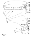
- the pelvic ring 10 consists of a flexible thermoplastic and is designed to hold the pelvis encloses a user about three quarters.
- the pelvic ring 10 is with a soft pad 11 and closing means 12 in the form of a Belt with buckle.
- the connecting means 16 consist of an upper metal rail 18, which provided with a chain joint 20 of three joints and a lower metal rail 22.
- the upper metal rail 18 is connected by means of two screws 24 with a fixing element 26, which allows the adjustable connection with the pelvic ring 10.
- the fixing element 26 has two horizontal Slotted holes 28, which a flexible screwing of the fixing element 26 allow by means of two screws 30 on the pelvic ring 10. In this way, the intersection of the pelvic ring 10 with the metal rail 18 are changed in the horizontal direction. In vertical direction is an adjustability through two slots 27 am given the upper end of the metal rail 18.
- At the bottom of the upper Metal rail 18 is connected to the femur pressure plate 13.
- the connection between the metal rail 18 and the femur pressure plate 13 is made by means of two rivets 32.
- the second metal rail closes 22 on. This is with the femur pressure plate 13 by means of two Screw 34 connected.
- the two screws 34 are arranged so that they protrude through a slot 36 in the metal rail 22 and on the opposite side to a not visible in Fig. 1 Manner are tightened.
- the length of the connecting means 16 can be changed by means of these two screws 34.
- the Condylenteil 14 consists of a plastic ring 38, which is such that it roughly shorts the user's thigh encloses three quarters. On the inside of this plastic ring 38 is a padding 40.
- the adaptability to various thigh circumferences is accomplished by means of a belt 42, the Thigh of the user at the rear of the plastic ring 38 not encompassed side of the Condylenteils 14 surrounds.
- the belt 42 is on one side by means of a Befest Trentsniets 44 with the plastic ring 38 connected. On the other hand, he is through a buckle 46 held, which is not visible in the perspective of FIG.
- the Connection between the metal rail 22 and the Condylenteil 14 is ensured by fastening means 48 which an insertion opening 50 for receiving the metal rail 22 have.
- fastening means 48 two screws 52, 54 on, which from the outside are screwed through the metal rail 22.
- the lower of these Screws 52 is thereby through a bore of the fastener 48 led.
- the upper screw 54 is formed by a circular arc segment-shaped Slot 56 led. In this way it is possible to tilt the condyle part 14 about the axis 58 by the screw 54 dissolved, the condyle portion 14 tilted and the screw 54 then is attracted again.
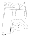
- FIG. 2 shows a bandage part 70 of a hip orthosis according to the invention from behind.
- the bandage part 70 has an upper portion 72, which encloses the hip of a user.
- a lower section 74 encloses together with a segment 76 the thigh of the User.
- the upper section 72 is closed on the rear side, while it opens on the front side in two ends 78, 80, which are connected together in the course of applying the orthosis can.
- the ends 78, 80 each have a hook-and-loop fastener 82, 84, wherein in the perspective of FIG. 2, only the Velcro 82 is recognizable.
- Guide portions 86 are provided by means of which the bandage part 70 can be connected to the pelvic ring 10 of the orthosis part 8.
- the segment 76 is connected to the lower portion 74 of the bandage portion 70 connected on the rear side by means of a zipper 88. On the other side, the segment 76 with the lower portion 74 the bandage part 70 is connected by means of a hook and loop fastener 90 become. The segment 76 is accordingly slightly off the bandage part 70 to solve.
- FIG. 3 shows the complete hip orthosis from the perspective of FIG. 1 in the assembled state. It can be seen that the orthosis part 8 is connected in several places with the bandage part 70.
- the pelvic ring 10 is in a non-visible manner through the attachment tabs 86 of the bandaging part 70 out. At the ends of the pad 11 the pelvic ring 10 is inserted into holding pockets 94 provided for this purpose.
- a chain hinge shell 96 is slipped, the the chain link 20 from contamination and mechanical damage protects.
- the femur pressure plate 13 is provided in a designated Pocket 98 introduced, which has a zipper 100, by means of which it can be opened and closed.
- the metal rail 22 is in the lower portion 74 of the bandage portion 70 on the Inside the bandaging part 70 out. It can be seen beyond that the segment 76 in the closed state, where it is on his Front with the lower portion 74 of the bandage part 70 by means of the Velcro 90 is connected. The two ends 78, 80 are in the state shown in Fig. 3 connected to each other. this happens on the one hand by means of the hook and loop fastener 82, 84.
- the orthosis part 8 is closed by means of closure 12, which in the illustrated Embodiment designed as a belt with a buckle.
- Fig. 4 shows the mobility of a chain joint with two joints 104, 106, as in a hip orthosis according to the invention application place. It can be seen that with the same orientation Connectors 108, 110 a flexible adjustment of the point of intersection 112a, 122b, 112c, 112d of the fittings 108, 110 is possible. On this way it allows such a chain joint consisting of two joints 104, 106 that a pivot axis of the total joint flexibly adjusted by the intersection 112a, 112b, 112c, 112d, that the pivot axis with the hinge axis of the hip joint matches. As a result, undesirable forces do not occur which act on the hip joint and favor a dislocation.
- FIG. 5 shows the flexibility of a chain link with three joints 114, 116, 118.
- a chain link with three joints 114, 116, 118 is insofar as a chain joint with two joints 104, 106, as in Fig. 4, superior, as that the distance 122 between the bottom joint 118 and the intersection 120a, 120b, 120c not of The position of the point of intersection is necessarily co-determined. Accordingly differ the different positions of the chain joint, which are shown in Fig. 5, only in terms of the position of Intersection point 120a, 120b, 120c.
- the distance 122 of the last joint 118 to intersection 120a, 120b, 120c is identical in all three states.
- the compulsory link which, as shown in Fig.
- Fig. 6 shows two states 124, 126 of a chain link, wherein from state 124 is how far the chain link in the maximum case can be deflected to the rear, while state 126 shows up to which degree the chain link is deflected maximum forward can.
- the maximum deflection shown at state 124 to the rear is about 150 °, with each individual joint 128, 130, 132 can be deflected by about 50 ° each. Under orthopedic aspects the deflection to the rear is hardly significant. An essential greater danger is based on a deflection forward because at a deflection beyond 70 ° the risk of dislocation of the Hip joint is significantly increased and such a thigh position, for example, when sitting, is common.
- each of the individual joints 128, 130, 132 each have a deflection of approx. 23 ° allows.
- the restriction of the respective angle is shown in the Embodiment realized via small metal pins 134.
- the Metal pins 134 are part of the joints. At the given angle the metal rail abuts against a respective metal pin 134 and is thereby prevented from further rotation relative to the joint.
- Fig. 7 shows the fixing element 26, with the metal rail 18 with the pelvic ring 10 is connected.
- the fixing element 26 is here connected by two screws 24 with the metal rail 18.
- two slots 28 are provided which allow the combination of metal rail 18 and fixing element 26th to attach to a customized location of the pelvic ring 10. This is done by means of the screws 30, which push to Zurechtschieben of the fixing element 26 are attracted to the adjusted position.
- the dashed lines show the metal rail 18 ', the fixing element 26 'with the two slots 28', as the position of the fixing element 26 and the metal rail 18 the pelvic ring 10 can be changed.
- the metal rail 18 has also two slots 27, which allow a vertical adjustment.
- FIG. 8 shows the fixing element 26 shown in FIG. 7, the metal rail 18 and the pelvic ring 10 in a sectional view.
- two wedge elements 25a, 25b are provided by means of which the abduction angle of the metal rail 18 can be adjusted.
- the left picture shows a setting where the acute angles of both Wedge elements 25a, 25b have in the opposite direction. Thereby their effect cancel each other out and the abduction angle of the Metal rail 18 is determined solely by the pelvic ring 10.
- In the right illustration shows the acute angle of both wedge elements 25a, 25b upward so that they each increase the abduction angle, ie the angle between a vertical and the metal rail, contribute.
- a finer vote is through the use other wedge elements possible, so that an orthopedic good on User-tailored abduction can be achieved.
- Fig. 9 shows the Condylenteil 14 in a view from above.
- the essential element of Condylenteils 14 is the plastic ring 38. It includes the thigh of the user in front and laterally.
- a pad 40 is provided which is connected to the plastic ring 38, for example with a Velcro or glued.
- the plastic ring 38 is dimensioned that he is not complete even with a narrow thigh embraces.
- a belt 42 is provided which on one side with a fastening rivet 44 is connected to the plastic ring 38.
- a holding device 46 is provided, through which the belt is pulled so that the condyle part 14 is tight around the user's thigh. Fixation of a belt 42 can be done for example via a hook and loop fastener 49.
- Fig. 10 shows the condyle part 14 shown in Fig. 9 from a lateral Perspective.
- the tilting mechanism which from the two screws 52, 54 and the curved slot 56.
- the dashed Illustration 53 shows a Condylenteil in one opposite the metal rail 22 tilted state.
Landscapes
- Health & Medical Sciences (AREA)
- Vascular Medicine (AREA)
- Animal Behavior & Ethology (AREA)
- Engineering & Computer Science (AREA)
- Biomedical Technology (AREA)
- Heart & Thoracic Surgery (AREA)
- Nursing (AREA)
- Life Sciences & Earth Sciences (AREA)
- Orthopedic Medicine & Surgery (AREA)
- General Health & Medical Sciences (AREA)
- Public Health (AREA)
- Veterinary Medicine (AREA)
- Orthopedics, Nursing, And Contraception (AREA)
- Prostheses (AREA)
- Manipulator (AREA)
Applications Claiming Priority (2)
| Application Number | Priority Date | Filing Date | Title |
|---|---|---|---|
| DE102004020980A DE102004020980A1 (de) | 2004-04-23 | 2004-04-23 | Modulare Hüftorthese |
| DE102004020980 | 2004-04-23 |
Publications (2)
| Publication Number | Publication Date |
|---|---|
| EP1588678A1 true EP1588678A1 (fr) | 2005-10-26 |
| EP1588678B1 EP1588678B1 (fr) | 2007-06-13 |
Family
ID=34935011
Family Applications (1)
| Application Number | Title | Priority Date | Filing Date |
|---|---|---|---|
| EP05007935A Expired - Lifetime EP1588678B1 (fr) | 2004-04-23 | 2005-04-12 | Orthèse de hanche modulaire |
Country Status (5)
| Country | Link |
|---|---|
| EP (1) | EP1588678B1 (fr) |
| JP (1) | JP4805601B2 (fr) |
| AT (1) | ATE364363T1 (fr) |
| DE (2) | DE102004020980A1 (fr) |
| DK (1) | DK1588678T3 (fr) |
Cited By (24)
| Publication number | Priority date | Publication date | Assignee | Title |
|---|---|---|---|---|
| CN101721270B (zh) * | 2008-10-20 | 2012-04-25 | 赵菁 | 臂撑式随身腰椎牵引腰带 |
| WO2012177700A3 (fr) * | 2011-06-20 | 2013-02-21 | Ossur Hf | Dispositif orthopédique, utilisation du dispositif orthopédique et son procédé de fabrication |
| EP2612625A1 (fr) * | 2012-01-09 | 2013-07-10 | Orthomerica Products, Inc. | Orthèse de hanche à composants multiples réglables |
| CN103860305A (zh) * | 2014-03-11 | 2014-06-18 | 加莎热特·杰力勒 | 缓慢牵张三维髋关节复位运动治疗装置 |
| EP2777655A3 (fr) * | 2013-03-15 | 2014-10-29 | Breg, Inc. | Sangle de limitation d'extension pour attelle de hanche |
| US8926537B2 (en) | 2009-02-26 | 2015-01-06 | Ossur Hf | Orthopedic device for treatment of the back |
| US9220625B2 (en) | 2009-11-04 | 2015-12-29 | Ossur Hf | Thoracic lumbar sacral orthosis |
| US9314363B2 (en) | 2013-01-24 | 2016-04-19 | Ossur Hf | Orthopedic device for treating complications of the hip |
| US9370440B2 (en) | 2012-01-13 | 2016-06-21 | Ossur Hf | Spinal orthosis |
| US9468554B2 (en) | 2013-01-24 | 2016-10-18 | Ossur Iceland Ehf | Orthopedic device for treating complications of the hip |
| US9554935B2 (en) | 2013-01-24 | 2017-01-31 | Ossur Hf | Orthopedic device for treating complications of the hip |
| US9572705B2 (en) | 2012-01-13 | 2017-02-21 | Ossur Hf | Spinal orthosis |
| US9795500B2 (en) | 2013-01-24 | 2017-10-24 | Ossur Hf | Orthopedic device for treating complications of the hip |
| US9872794B2 (en) | 2012-09-19 | 2018-01-23 | Ossur Hf | Panel attachment and circumference adjustment systems for an orthopedic device |
| US10159592B2 (en) | 2015-02-27 | 2018-12-25 | Ossur Iceland Ehf | Spinal orthosis, kit and method for using the same |
| WO2019052805A1 (fr) * | 2017-09-14 | 2019-03-21 | Otto Bock Healthcare Products Gmbh | Dispositif d'articulation |
| WO2019106153A1 (fr) * | 2017-12-01 | 2019-06-06 | Ottobock Se & Co. Kgaa | Dispositif de réglage et orthèse pourvue d'un dispositif de réglage |
| US10561520B2 (en) | 2015-02-27 | 2020-02-18 | Ossur Iceland Ehf | Spinal orthosis, kit and method for using the same |
| US10624775B2 (en) | 2013-03-15 | 2020-04-21 | Breg, Inc. | Strapping system for securing an orthopedic brace to the body |
| USD886307S1 (en) | 2019-06-04 | 2020-06-02 | Impact Ip, Llc | Hip brace |
| USD890355S1 (en) | 2020-02-20 | 2020-07-14 | Impact Ip, Llc | Hip brace ice pack |
| US11000439B2 (en) | 2017-09-28 | 2021-05-11 | Ossur Iceland Ehf | Body interface |
| CN113262093A (zh) * | 2021-07-07 | 2021-08-17 | 中国人民解放军空军军医大学 | 一种多功能骨盆、髋关节创伤急救固定器 |
| US11246734B2 (en) | 2017-09-07 | 2022-02-15 | Ossur Iceland Ehf | Thoracic lumbar sacral orthosis attachment |
Families Citing this family (10)
| Publication number | Priority date | Publication date | Assignee | Title |
|---|---|---|---|---|
| KR100731961B1 (ko) | 2006-02-24 | 2007-06-29 | 김상호 | 다리깁스 고정기 |
| DE102006018881A1 (de) * | 2006-04-24 | 2007-11-15 | Shuku, Aida | Hüftdysplasie-Bandage |
| DE202009004817U1 (de) | 2009-05-14 | 2010-09-30 | Tautz, Dr. Christian & Gröger, Achim & Barth, Hans-Peter GbR (vertretungsberechtigter Gesellschafter: Herrn Hans-Peter Barth, 63599 Biebergemünd) | Hüftgelenk-Stützeinrichtung |
| DE202009013955U1 (de) | 2009-10-14 | 2010-02-25 | Pro-Walk Rehabilitationshilfen und Sanitätsbedarf GmbH | Einstellbares Hüftgelenk für eine beckenübergreifende Orthese |
| CN102846417A (zh) * | 2012-09-27 | 2013-01-02 | 胡大勇 | 动态稳定髋关节支具系统 |
| DE102013203354B4 (de) | 2013-02-28 | 2018-07-19 | Wilhelm Julius Teufel Gmbh | Orthesenspange und Bausatz |
| DE102013203353B4 (de) | 2013-02-28 | 2018-07-19 | Wilhelm Julius Teufel Gmbh | Hüftorthese |
| JP2020069189A (ja) * | 2018-10-31 | 2020-05-07 | 小澤 浩司 | 姿勢維持装置 |
| EP4472577A2 (fr) | 2022-02-02 | 2024-12-11 | Djo, Llc | Appareils orthopédiques à montant unique destinés à traiter l'arthrose et méthodes associées |
| DE102023133446A1 (de) * | 2023-11-29 | 2025-06-05 | Bort Gmbh | Hüftorthese zur Mobilisierung eines Hüftgelenks |
Citations (5)
| Publication number | Priority date | Publication date | Assignee | Title |
|---|---|---|---|---|
| US3902482A (en) * | 1974-05-21 | 1975-09-02 | George A Taylor | Mechanical joint for an orthopedic brace or prosthesis |
| US4144881A (en) * | 1977-06-06 | 1979-03-20 | Chappell Cluff E | Apparel worn for the aid and protection of the body and for the support and assistance of impaired joint function |
| US4393542A (en) * | 1980-07-21 | 1983-07-19 | Gonzalo Martinez | Polycentric hinge for cast-braces |
| DE4222601A1 (de) * | 1992-07-09 | 1994-01-13 | Michael Klopf | Kniegelenk-Orthese |
| US6039707A (en) * | 1999-02-16 | 2000-03-21 | Crawford; Michael K. | Pelvic support and walking assistance device |
Family Cites Families (14)
| Publication number | Priority date | Publication date | Assignee | Title |
|---|---|---|---|---|
| DE271587C (fr) * | ||||
| JPS5627247A (en) * | 1979-08-09 | 1981-03-17 | Toshirou Nakamura | Hip joint abducting equipment for night |
| FR2506604A1 (fr) * | 1981-06-01 | 1982-12-03 | Salort Guy | Appareillage externe de station verticale et de marche pour handicapes moteurs des membres inferieurs |
| JPH027545Y2 (fr) * | 1985-07-01 | 1990-02-22 | ||
| GB8605472D0 (en) * | 1986-03-05 | 1986-04-09 | Meyer Paul A R | Leg restraint |
| US4777941A (en) * | 1987-07-29 | 1988-10-18 | Borig Donald A | Orthopedic knee prosthesis and hinge |
| US4905678A (en) * | 1988-10-18 | 1990-03-06 | Medical Designs, Inc. | Hip stabilizer |
| EP0413424A1 (fr) * | 1989-08-14 | 1991-02-20 | Protectair Limited | Charnière orthopédique à deux pivots, et système de commande de pivotage à cet effet |
| JP2877861B2 (ja) * | 1989-11-24 | 1999-04-05 | アルケア株式会社 | 膝装具 |
| DE29511920U1 (de) * | 1995-07-24 | 1995-09-28 | Göbel, Dieter, Dr.med., 80333 München | Hüftkopf-Entlastungsvorrichtung für Morbus-Perthes-Patienten |
| US5840050A (en) * | 1996-09-23 | 1998-11-24 | Lerman; Max | Post-operative hip brace |
| JP3337384B2 (ja) * | 1996-12-04 | 2002-10-21 | 株式会社田中企画 | 医療用コルセット |
| JP2000189448A (ja) * | 1998-10-20 | 2000-07-11 | Rakuhoku Gishi:Kk | 股関節用ダイヤルロック継ぎ手及び該ダイヤルロック継ぎ手を含む股関節装具 |
| US6540703B1 (en) * | 2000-11-20 | 2003-04-01 | Max Lerman | Post-operative hip abduction orthosis |
-
2004
- 2004-04-23 DE DE102004020980A patent/DE102004020980A1/de not_active Withdrawn
-
2005
- 2005-04-12 EP EP05007935A patent/EP1588678B1/fr not_active Expired - Lifetime
- 2005-04-12 AT AT05007935T patent/ATE364363T1/de active
- 2005-04-12 DE DE502005000837T patent/DE502005000837D1/de not_active Expired - Lifetime
- 2005-04-12 DK DK05007935T patent/DK1588678T3/da active
- 2005-04-25 JP JP2005126786A patent/JP4805601B2/ja not_active Expired - Fee Related
Patent Citations (5)
| Publication number | Priority date | Publication date | Assignee | Title |
|---|---|---|---|---|
| US3902482A (en) * | 1974-05-21 | 1975-09-02 | George A Taylor | Mechanical joint for an orthopedic brace or prosthesis |
| US4144881A (en) * | 1977-06-06 | 1979-03-20 | Chappell Cluff E | Apparel worn for the aid and protection of the body and for the support and assistance of impaired joint function |
| US4393542A (en) * | 1980-07-21 | 1983-07-19 | Gonzalo Martinez | Polycentric hinge for cast-braces |
| DE4222601A1 (de) * | 1992-07-09 | 1994-01-13 | Michael Klopf | Kniegelenk-Orthese |
| US6039707A (en) * | 1999-02-16 | 2000-03-21 | Crawford; Michael K. | Pelvic support and walking assistance device |
Cited By (54)
| Publication number | Priority date | Publication date | Assignee | Title |
|---|---|---|---|---|
| CN101721270B (zh) * | 2008-10-20 | 2012-04-25 | 赵菁 | 臂撑式随身腰椎牵引腰带 |
| US9439800B2 (en) | 2009-01-14 | 2016-09-13 | Ossur Hf | Orthopedic device, use of orthopedic device and method for producing same |
| US10828186B2 (en) | 2009-02-26 | 2020-11-10 | Ossur Hf | Orthopedic device for treatment of the back |
| US9414953B2 (en) | 2009-02-26 | 2016-08-16 | Ossur Hf | Orthopedic device for treatment of the back |
| US12127965B2 (en) | 2009-02-26 | 2024-10-29 | Ossur Hf | Orthopedic device for treatment of the back |
| US8926537B2 (en) | 2009-02-26 | 2015-01-06 | Ossur Hf | Orthopedic device for treatment of the back |
| US8945034B2 (en) | 2009-02-26 | 2015-02-03 | Ossur Hf | Orthopedic device for treatment of the back |
| US10617552B2 (en) | 2009-11-04 | 2020-04-14 | Ossur Hf | Thoracic lumbar sacral orthosis |
| US9597219B2 (en) | 2009-11-04 | 2017-03-21 | Ossur Hf | Thoracic lumbar sacral orthosis |
| US9220625B2 (en) | 2009-11-04 | 2015-12-29 | Ossur Hf | Thoracic lumbar sacral orthosis |
| CN103747763B (zh) * | 2011-06-20 | 2016-03-30 | 奥索有限责任公司 | 矫形装置、矫形装置的使用及其制造方法 |
| CN103747763A (zh) * | 2011-06-20 | 2014-04-23 | 奥索有限责任公司 | 矫形装置、矫形装置的使用及其制造方法 |
| WO2012177700A3 (fr) * | 2011-06-20 | 2013-02-21 | Ossur Hf | Dispositif orthopédique, utilisation du dispositif orthopédique et son procédé de fabrication |
| US8708941B2 (en) | 2012-01-09 | 2014-04-29 | Orthomerica Products, Inc. | Adjustable multi-component hip orthosis |
| EP2612625A1 (fr) * | 2012-01-09 | 2013-07-10 | Orthomerica Products, Inc. | Orthèse de hanche à composants multiples réglables |
| US9370440B2 (en) | 2012-01-13 | 2016-06-21 | Ossur Hf | Spinal orthosis |
| US12186226B2 (en) | 2012-01-13 | 2025-01-07 | Ossur Hf | Spinal orthosis |
| US10898365B2 (en) | 2012-01-13 | 2021-01-26 | Ossur Hf | Spinal orthosis |
| US9572705B2 (en) | 2012-01-13 | 2017-02-21 | Ossur Hf | Spinal orthosis |
| US11484428B2 (en) | 2012-09-19 | 2022-11-01 | Ossur Hf | Panel attachment and circumference adjustment systems for an orthopedic device |
| US10980657B2 (en) | 2012-09-19 | 2021-04-20 | Ossur Hf | Panel attachment and circumference adjustment systems for an orthopedic device |
| US9872794B2 (en) | 2012-09-19 | 2018-01-23 | Ossur Hf | Panel attachment and circumference adjustment systems for an orthopedic device |
| US9393144B2 (en) | 2013-01-24 | 2016-07-19 | Ossur Hf | Orthopedic device for treating complications of the hip |
| US9554935B2 (en) | 2013-01-24 | 2017-01-31 | Ossur Hf | Orthopedic device for treating complications of the hip |
| US12433778B2 (en) | 2013-01-24 | 2025-10-07 | Ossur Hf | Orthopedic device for treating complications of the hip |
| US9314363B2 (en) | 2013-01-24 | 2016-04-19 | Ossur Hf | Orthopedic device for treating complications of the hip |
| US11259948B2 (en) | 2013-01-24 | 2022-03-01 | Ossur Hf | Orthopedic device for treating complications of the hip |
| US9468554B2 (en) | 2013-01-24 | 2016-10-18 | Ossur Iceland Ehf | Orthopedic device for treating complications of the hip |
| US10357391B2 (en) | 2013-01-24 | 2019-07-23 | Ossur Hf | Orthopedic device for treating complications of the hip |
| US9987158B2 (en) | 2013-01-24 | 2018-06-05 | Ossur Hf | Orthopedic device for treating complications of the hip |
| US9795500B2 (en) | 2013-01-24 | 2017-10-24 | Ossur Hf | Orthopedic device for treating complications of the hip |
| EP2777655A3 (fr) * | 2013-03-15 | 2014-10-29 | Breg, Inc. | Sangle de limitation d'extension pour attelle de hanche |
| US10624775B2 (en) | 2013-03-15 | 2020-04-21 | Breg, Inc. | Strapping system for securing an orthopedic brace to the body |
| CN103860305B (zh) * | 2014-03-11 | 2016-05-11 | 加莎热特·杰力勒 | 缓慢牵张三维髋关节复位运动治疗装置 |
| CN103860305A (zh) * | 2014-03-11 | 2014-06-18 | 加莎热特·杰力勒 | 缓慢牵张三维髋关节复位运动治疗装置 |
| US10307283B2 (en) | 2014-03-11 | 2019-06-04 | Jielile Jiasharete | Therapeutic device for slowly stretching three-dimensional hip joint for reposition movement |
| US10561520B2 (en) | 2015-02-27 | 2020-02-18 | Ossur Iceland Ehf | Spinal orthosis, kit and method for using the same |
| US11571323B2 (en) | 2015-02-27 | 2023-02-07 | Ossur Iceland Ehf | Spinal orthosis, kit and method for using the same |
| US10159592B2 (en) | 2015-02-27 | 2018-12-25 | Ossur Iceland Ehf | Spinal orthosis, kit and method for using the same |
| US11273064B2 (en) | 2015-02-27 | 2022-03-15 | Ossur Iceland Ehf | Spinal orthosis, kit and method for using the same |
| US12090079B2 (en) | 2017-09-07 | 2024-09-17 | Ossur Iceland Ehf | Thoracic lumbar sacral orthosis attachment |
| US11246734B2 (en) | 2017-09-07 | 2022-02-15 | Ossur Iceland Ehf | Thoracic lumbar sacral orthosis attachment |
| US11684506B2 (en) | 2017-09-07 | 2023-06-27 | Ossur Iceland Ehf | Thoracic lumbar sacral orthosis attachment |
| CN111093571A (zh) * | 2017-09-14 | 2020-05-01 | 奥托·博克保健产品有限公司 | 关节装置 |
| WO2019052805A1 (fr) * | 2017-09-14 | 2019-03-21 | Otto Bock Healthcare Products Gmbh | Dispositif d'articulation |
| US11000439B2 (en) | 2017-09-28 | 2021-05-11 | Ossur Iceland Ehf | Body interface |
| US11850206B2 (en) | 2017-09-28 | 2023-12-26 | Ossur Iceland Ehf | Body interface |
| KR20200095505A (ko) * | 2017-12-01 | 2020-08-10 | 오토복 에스에 운트 코. 카게아아 | 조절장치 및 조절장치를 구비한 보조기 |
| KR102442130B1 (ko) * | 2017-12-01 | 2022-09-08 | 오토복 에스에 운트 코. 카게아아 | 조절장치 및 조절장치를 구비한 보조기 |
| WO2019106153A1 (fr) * | 2017-12-01 | 2019-06-06 | Ottobock Se & Co. Kgaa | Dispositif de réglage et orthèse pourvue d'un dispositif de réglage |
| CN111417368A (zh) * | 2017-12-01 | 2020-07-14 | 奥托博克欧洲股份两合公司 | 调节装置和具有调节装置的矫形器 |
| USD886307S1 (en) | 2019-06-04 | 2020-06-02 | Impact Ip, Llc | Hip brace |
| USD890355S1 (en) | 2020-02-20 | 2020-07-14 | Impact Ip, Llc | Hip brace ice pack |
| CN113262093A (zh) * | 2021-07-07 | 2021-08-17 | 中国人民解放军空军军医大学 | 一种多功能骨盆、髋关节创伤急救固定器 |
Also Published As
| Publication number | Publication date |
|---|---|
| ATE364363T1 (de) | 2007-07-15 |
| JP4805601B2 (ja) | 2011-11-02 |
| DE102004020980A1 (de) | 2005-11-10 |
| DE502005000837D1 (de) | 2007-07-26 |
| DK1588678T3 (da) | 2007-07-16 |
| EP1588678B1 (fr) | 2007-06-13 |
| JP2005305174A (ja) | 2005-11-04 |
Similar Documents
| Publication | Publication Date | Title |
|---|---|---|
| EP1588678B1 (fr) | Orthèse de hanche modulaire | |
| DE3854651T2 (de) | Gelenkverbindung für orthopädische Kniestütze. | |
| DE60124620T2 (de) | Modulare verstellbare Hüft-Orthese und Adduktions-/Abduktions-Gelenk | |
| DE69523080T2 (de) | Knieorthese zur Behandlung von Osteoarthritis | |
| EP0991381B1 (fr) | Dispositif pour stabiliser une articulation | |
| EP0677282B1 (fr) | Eclisse de genou | |
| EP0917864B1 (fr) | Orthèse minimale pour le traitement de l'osteoporose | |
| EP0270555B1 (fr) | Prothese orthopedique de l'articulation tibio-tarsienne | |
| DE69316541T2 (de) | Schulterschiene | |
| DE69616629T2 (de) | Abduktionsschiene für Schulter und Arm | |
| DE112012004113B4 (de) | Orthese zur Korrektur von Oberarmfrakturen | |
| DE102009038517B4 (de) | Baukastensystem zur Zusammenstellung einer Orthese für ein Knie und Verfahren zum Umbau einer Orthese aus diesem Baukastensystem | |
| EP3378448B1 (fr) | Orthèse du genou modulaire | |
| EP0567673B1 (fr) | Orthèse de l'articulation du genou | |
| EP0164374A1 (fr) | Prothese orthopedique pour l'articulation du genou. | |
| WO2003020187A1 (fr) | Orthese de genou | |
| EP0880346A1 (fr) | Orthese du genou | |
| DE60205192T2 (de) | Gelenkschiene zur Steuerung und Regelung der Beugung des Kniegelenks | |
| DE69815379T2 (de) | Orthese zum verhindern einer hyperextension des knies | |
| EP2874579B1 (fr) | Orthèse d'abduction d'épaule | |
| DE3505528A1 (de) | Abduktionsschiene zum entlasten des schultergelenkes | |
| DE4418855A1 (de) | Knieorthese | |
| EP4353204B1 (fr) | Orthèse dorsale pour stabiliser le dos d'un patient | |
| DE8912344U1 (de) | Dynamische Abduktionsschiene | |
| DE3433843A1 (de) | Kniestuetze zur verhinderung von rotationen |
Legal Events
| Date | Code | Title | Description |
|---|---|---|---|
| PUAI | Public reference made under article 153(3) epc to a published international application that has entered the european phase |
Free format text: ORIGINAL CODE: 0009012 |
|
| AK | Designated contracting states |
Kind code of ref document: A1 Designated state(s): AT BE BG CH CY CZ DE DK EE ES FI FR GB GR HU IE IS IT LI LT LU MC NL PL PT RO SE SI SK TR |
|
| AX | Request for extension of the european patent |
Extension state: AL BA HR LV MK YU |
|
| 17P | Request for examination filed |
Effective date: 20051129 |
|
| AKX | Designation fees paid |
Designated state(s): AT BE BG CH CY CZ DE DK EE ES FI FR GB GR HU IE IS IT LI LT LU MC NL PL PT RO SE SI SK TR |
|
| GRAP | Despatch of communication of intention to grant a patent |
Free format text: ORIGINAL CODE: EPIDOSNIGR1 |
|
| GRAS | Grant fee paid |
Free format text: ORIGINAL CODE: EPIDOSNIGR3 |
|
| GRAA | (expected) grant |
Free format text: ORIGINAL CODE: 0009210 |
|
| AK | Designated contracting states |
Kind code of ref document: B1 Designated state(s): AT BE BG CH CY CZ DE DK EE ES FI FR GB GR HU IE IS IT LI LT LU MC NL PL PT RO SE SI SK TR |
|
| REG | Reference to a national code |
Ref country code: GB Ref legal event code: FG4D Free format text: NOT ENGLISH |
|
| REG | Reference to a national code |
Ref country code: CH Ref legal event code: EP |
|
| REG | Reference to a national code |
Ref country code: IE Ref legal event code: FG4D Free format text: LANGUAGE OF EP DOCUMENT: GERMAN |
|
| REG | Reference to a national code |
Ref country code: DK Ref legal event code: T3 |
|
| REF | Corresponds to: |
Ref document number: 502005000837 Country of ref document: DE Date of ref document: 20070726 Kind code of ref document: P |
|
| REG | Reference to a national code |
Ref country code: CH Ref legal event code: NV Representative=s name: ZIMMERLI, WAGNER & PARTNER AG |
|
| GBT | Gb: translation of ep patent filed (gb section 77(6)(a)/1977) |
Effective date: 20070823 |
|
| REG | Reference to a national code |
Ref country code: SE Ref legal event code: TRGR |
|
| PG25 | Lapsed in a contracting state [announced via postgrant information from national office to epo] |
Ref country code: PL Free format text: LAPSE BECAUSE OF FAILURE TO SUBMIT A TRANSLATION OF THE DESCRIPTION OR TO PAY THE FEE WITHIN THE PRESCRIBED TIME-LIMIT Effective date: 20070613 |
|
| ET | Fr: translation filed | ||
| PG25 | Lapsed in a contracting state [announced via postgrant information from national office to epo] |
Ref country code: CZ Free format text: LAPSE BECAUSE OF FAILURE TO SUBMIT A TRANSLATION OF THE DESCRIPTION OR TO PAY THE FEE WITHIN THE PRESCRIBED TIME-LIMIT Effective date: 20070613 Ref country code: IS Free format text: LAPSE BECAUSE OF FAILURE TO SUBMIT A TRANSLATION OF THE DESCRIPTION OR TO PAY THE FEE WITHIN THE PRESCRIBED TIME-LIMIT Effective date: 20071013 Ref country code: PT Free format text: LAPSE BECAUSE OF FAILURE TO SUBMIT A TRANSLATION OF THE DESCRIPTION OR TO PAY THE FEE WITHIN THE PRESCRIBED TIME-LIMIT Effective date: 20071113 Ref country code: SI Free format text: LAPSE BECAUSE OF FAILURE TO SUBMIT A TRANSLATION OF THE DESCRIPTION OR TO PAY THE FEE WITHIN THE PRESCRIBED TIME-LIMIT Effective date: 20070613 Ref country code: BG Free format text: LAPSE BECAUSE OF FAILURE TO SUBMIT A TRANSLATION OF THE DESCRIPTION OR TO PAY THE FEE WITHIN THE PRESCRIBED TIME-LIMIT Effective date: 20070913 Ref country code: ES Free format text: LAPSE BECAUSE OF FAILURE TO SUBMIT A TRANSLATION OF THE DESCRIPTION OR TO PAY THE FEE WITHIN THE PRESCRIBED TIME-LIMIT Effective date: 20070924 |
|
| PG25 | Lapsed in a contracting state [announced via postgrant information from national office to epo] |
Ref country code: SK Free format text: LAPSE BECAUSE OF FAILURE TO SUBMIT A TRANSLATION OF THE DESCRIPTION OR TO PAY THE FEE WITHIN THE PRESCRIBED TIME-LIMIT Effective date: 20070613 Ref country code: LT Free format text: LAPSE BECAUSE OF FAILURE TO SUBMIT A TRANSLATION OF THE DESCRIPTION OR TO PAY THE FEE WITHIN THE PRESCRIBED TIME-LIMIT Effective date: 20070613 |
|
| PLBE | No opposition filed within time limit |
Free format text: ORIGINAL CODE: 0009261 |
|
| STAA | Information on the status of an ep patent application or granted ep patent |
Free format text: STATUS: NO OPPOSITION FILED WITHIN TIME LIMIT |
|
| PG25 | Lapsed in a contracting state [announced via postgrant information from national office to epo] |
Ref country code: GR Free format text: LAPSE BECAUSE OF FAILURE TO SUBMIT A TRANSLATION OF THE DESCRIPTION OR TO PAY THE FEE WITHIN THE PRESCRIBED TIME-LIMIT Effective date: 20070914 Ref country code: IT Free format text: LAPSE BECAUSE OF FAILURE TO SUBMIT A TRANSLATION OF THE DESCRIPTION OR TO PAY THE FEE WITHIN THE PRESCRIBED TIME-LIMIT Effective date: 20070613 |
|
| 26N | No opposition filed |
Effective date: 20080314 |
|
| PG25 | Lapsed in a contracting state [announced via postgrant information from national office to epo] |
Ref country code: RO Free format text: LAPSE BECAUSE OF FAILURE TO SUBMIT A TRANSLATION OF THE DESCRIPTION OR TO PAY THE FEE WITHIN THE PRESCRIBED TIME-LIMIT Effective date: 20070613 |
|
| PG25 | Lapsed in a contracting state [announced via postgrant information from national office to epo] |
Ref country code: MC Free format text: LAPSE BECAUSE OF NON-PAYMENT OF DUE FEES Effective date: 20080430 |
|
| PG25 | Lapsed in a contracting state [announced via postgrant information from national office to epo] |
Ref country code: EE Free format text: LAPSE BECAUSE OF FAILURE TO SUBMIT A TRANSLATION OF THE DESCRIPTION OR TO PAY THE FEE WITHIN THE PRESCRIBED TIME-LIMIT Effective date: 20070613 |
|
| PG25 | Lapsed in a contracting state [announced via postgrant information from national office to epo] |
Ref country code: FI Free format text: LAPSE BECAUSE OF FAILURE TO SUBMIT A TRANSLATION OF THE DESCRIPTION OR TO PAY THE FEE WITHIN THE PRESCRIBED TIME-LIMIT Effective date: 20070613 |
|
| PG25 | Lapsed in a contracting state [announced via postgrant information from national office to epo] |
Ref country code: CY Free format text: LAPSE BECAUSE OF FAILURE TO SUBMIT A TRANSLATION OF THE DESCRIPTION OR TO PAY THE FEE WITHIN THE PRESCRIBED TIME-LIMIT Effective date: 20070613 |
|
| REG | Reference to a national code |
Ref country code: CH Ref legal event code: PFA Owner name: WILHELM JULIUS TEUFEL GMBH Free format text: WILHELM JULIUS TEUFEL GMBH#ROBERT-BOSCH-STRASSE 15#73117 WANGEN (DE) -TRANSFER TO- WILHELM JULIUS TEUFEL GMBH#ROBERT-BOSCH-STRASSE 15#73117 WANGEN (DE) |
|
| PG25 | Lapsed in a contracting state [announced via postgrant information from national office to epo] |
Ref country code: LU Free format text: LAPSE BECAUSE OF NON-PAYMENT OF DUE FEES Effective date: 20080412 Ref country code: HU Free format text: LAPSE BECAUSE OF FAILURE TO SUBMIT A TRANSLATION OF THE DESCRIPTION OR TO PAY THE FEE WITHIN THE PRESCRIBED TIME-LIMIT Effective date: 20071214 |
|
| PG25 | Lapsed in a contracting state [announced via postgrant information from national office to epo] |
Ref country code: TR Free format text: LAPSE BECAUSE OF FAILURE TO SUBMIT A TRANSLATION OF THE DESCRIPTION OR TO PAY THE FEE WITHIN THE PRESCRIBED TIME-LIMIT Effective date: 20070613 |
|
| PGFP | Annual fee paid to national office [announced via postgrant information from national office to epo] |
Ref country code: NL Payment date: 20120425 Year of fee payment: 8 Ref country code: BE Payment date: 20120424 Year of fee payment: 8 Ref country code: DK Payment date: 20120424 Year of fee payment: 8 Ref country code: CH Payment date: 20120423 Year of fee payment: 8 Ref country code: IE Payment date: 20120419 Year of fee payment: 8 Ref country code: DE Payment date: 20120621 Year of fee payment: 8 |
|
| PGFP | Annual fee paid to national office [announced via postgrant information from national office to epo] |
Ref country code: SE Payment date: 20120423 Year of fee payment: 8 Ref country code: GB Payment date: 20120404 Year of fee payment: 8 Ref country code: FR Payment date: 20120511 Year of fee payment: 8 |
|
| PGFP | Annual fee paid to national office [announced via postgrant information from national office to epo] |
Ref country code: AT Payment date: 20120420 Year of fee payment: 8 |
|
| BERE | Be: lapsed |
Owner name: WILHELM JULIUS TEUFEL G.M.B.H. Effective date: 20130430 |
|
| REG | Reference to a national code |
Ref country code: NL Ref legal event code: V1 Effective date: 20131101 |
|
| REG | Reference to a national code |
Ref country code: CH Ref legal event code: PL |
|
| REG | Reference to a national code |
Ref country code: SE Ref legal event code: EUG |
|
| REG | Reference to a national code |
Ref country code: DK Ref legal event code: EBP Effective date: 20130430 |
|
| REG | Reference to a national code |
Ref country code: AT Ref legal event code: MM01 Ref document number: 364363 Country of ref document: AT Kind code of ref document: T Effective date: 20130430 |
|
| GBPC | Gb: european patent ceased through non-payment of renewal fee |
Effective date: 20130412 |
|
| REG | Reference to a national code |
Ref country code: IE Ref legal event code: MM4A |
|
| PG25 | Lapsed in a contracting state [announced via postgrant information from national office to epo] |
Ref country code: AT Free format text: LAPSE BECAUSE OF NON-PAYMENT OF DUE FEES Effective date: 20130430 Ref country code: DE Free format text: LAPSE BECAUSE OF NON-PAYMENT OF DUE FEES Effective date: 20131101 Ref country code: BE Free format text: LAPSE BECAUSE OF NON-PAYMENT OF DUE FEES Effective date: 20130430 Ref country code: GB Free format text: LAPSE BECAUSE OF NON-PAYMENT OF DUE FEES Effective date: 20130412 Ref country code: SE Free format text: LAPSE BECAUSE OF NON-PAYMENT OF DUE FEES Effective date: 20130413 Ref country code: CH Free format text: LAPSE BECAUSE OF NON-PAYMENT OF DUE FEES Effective date: 20130430 Ref country code: LI Free format text: LAPSE BECAUSE OF NON-PAYMENT OF DUE FEES Effective date: 20130430 |
|
| REG | Reference to a national code |
Ref country code: FR Ref legal event code: ST Effective date: 20131231 |
|
| REG | Reference to a national code |
Ref country code: DE Ref legal event code: R119 Ref document number: 502005000837 Country of ref document: DE Effective date: 20131101 |
|
| PG25 | Lapsed in a contracting state [announced via postgrant information from national office to epo] |
Ref country code: NL Free format text: LAPSE BECAUSE OF NON-PAYMENT OF DUE FEES Effective date: 20131101 Ref country code: FR Free format text: LAPSE BECAUSE OF NON-PAYMENT OF DUE FEES Effective date: 20130430 |
|
| PG25 | Lapsed in a contracting state [announced via postgrant information from national office to epo] |
Ref country code: IE Free format text: LAPSE BECAUSE OF NON-PAYMENT OF DUE FEES Effective date: 20130412 Ref country code: DK Free format text: LAPSE BECAUSE OF NON-PAYMENT OF DUE FEES Effective date: 20130430 |