EP1588729B1 - Système de délivrance de liquide de type extrusion - Google Patents
Système de délivrance de liquide de type extrusion Download PDFInfo
- Publication number
- EP1588729B1 EP1588729B1 EP05252088A EP05252088A EP1588729B1 EP 1588729 B1 EP1588729 B1 EP 1588729B1 EP 05252088 A EP05252088 A EP 05252088A EP 05252088 A EP05252088 A EP 05252088A EP 1588729 B1 EP1588729 B1 EP 1588729B1
- Authority
- EP
- European Patent Office
- Prior art keywords
- plunger
- liquid delivery
- hooks
- extrusion
- mover
- Prior art date
- Legal status (The legal status is an assumption and is not a legal conclusion. Google has not performed a legal analysis and makes no representation as to the accuracy of the status listed.)
- Expired - Lifetime
Links
- 239000007788 liquid Substances 0.000 title claims description 62
- 230000003287 optical effect Effects 0.000 description 7
- 239000003814 drug Substances 0.000 description 4
- 230000010365 information processing Effects 0.000 description 3
- 238000000034 method Methods 0.000 description 3
- 238000010276 construction Methods 0.000 description 2
- 238000010586 diagram Methods 0.000 description 2
- 230000000903 blocking effect Effects 0.000 description 1
- 229940079593 drug Drugs 0.000 description 1
- 238000002347 injection Methods 0.000 description 1
- 239000007924 injection Substances 0.000 description 1
- 238000004519 manufacturing process Methods 0.000 description 1
Images



Classifications
-
- A—HUMAN NECESSITIES
- A61—MEDICAL OR VETERINARY SCIENCE; HYGIENE
- A61M—DEVICES FOR INTRODUCING MEDIA INTO, OR ONTO, THE BODY; DEVICES FOR TRANSDUCING BODY MEDIA OR FOR TAKING MEDIA FROM THE BODY; DEVICES FOR PRODUCING OR ENDING SLEEP OR STUPOR
- A61M5/00—Devices for bringing media into the body in a subcutaneous, intra-vascular or intramuscular way; Accessories therefor, e.g. filling or cleaning devices, arm-rests
- A61M5/14—Infusion devices, e.g. infusing by gravity; Blood infusion; Accessories therefor
- A61M5/142—Pressure infusion, e.g. using pumps
- A61M5/145—Pressure infusion, e.g. using pumps using pressurised reservoirs, e.g. pressurised by means of pistons
- A61M5/1452—Pressure infusion, e.g. using pumps using pressurised reservoirs, e.g. pressurised by means of pistons pressurised by means of pistons
- A61M5/1458—Means for capture of the plunger flange
-
- A—HUMAN NECESSITIES
- A61—MEDICAL OR VETERINARY SCIENCE; HYGIENE
- A61M—DEVICES FOR INTRODUCING MEDIA INTO, OR ONTO, THE BODY; DEVICES FOR TRANSDUCING BODY MEDIA OR FOR TAKING MEDIA FROM THE BODY; DEVICES FOR PRODUCING OR ENDING SLEEP OR STUPOR
- A61M2205/00—General characteristics of the apparatus
- A61M2205/14—Detection of the presence or absence of a tube, a connector or a container in an apparatus
-
- A—HUMAN NECESSITIES
- A61—MEDICAL OR VETERINARY SCIENCE; HYGIENE
- A61M—DEVICES FOR INTRODUCING MEDIA INTO, OR ONTO, THE BODY; DEVICES FOR TRANSDUCING BODY MEDIA OR FOR TAKING MEDIA FROM THE BODY; DEVICES FOR PRODUCING OR ENDING SLEEP OR STUPOR
- A61M39/00—Tubes, tube connectors, tube couplings, valves, access sites or the like, specially adapted for medical use
- A61M39/22—Valves or arrangement of valves
- A61M39/28—Clamping means for squeezing flexible tubes, e.g. roller clamps
-
- A—HUMAN NECESSITIES
- A61—MEDICAL OR VETERINARY SCIENCE; HYGIENE
- A61M—DEVICES FOR INTRODUCING MEDIA INTO, OR ONTO, THE BODY; DEVICES FOR TRANSDUCING BODY MEDIA OR FOR TAKING MEDIA FROM THE BODY; DEVICES FOR PRODUCING OR ENDING SLEEP OR STUPOR
- A61M5/00—Devices for bringing media into the body in a subcutaneous, intra-vascular or intramuscular way; Accessories therefor, e.g. filling or cleaning devices, arm-rests
- A61M5/14—Infusion devices, e.g. infusing by gravity; Blood infusion; Accessories therefor
- A61M5/142—Pressure infusion, e.g. using pumps
- A61M5/145—Pressure infusion, e.g. using pumps using pressurised reservoirs, e.g. pressurised by means of pistons
- A61M5/1452—Pressure infusion, e.g. using pumps using pressurised reservoirs, e.g. pressurised by means of pistons pressurised by means of pistons
- A61M5/1456—Pressure infusion, e.g. using pumps using pressurised reservoirs, e.g. pressurised by means of pistons pressurised by means of pistons with a replaceable reservoir comprising a piston rod to be moved into the reservoir, e.g. the piston rod is part of the removable reservoir
Definitions
- the present invention relates to an extrusion-type liquid delivery apparatus to deliver a liquid contained beforehand in a container with a plunger, such as an extrusion-type liquid delivery apparatus for medical use.
- the extrusion-type liquid delivery apparatus which pushes a liquid contained in a container out with a plunger along the inner wall of the container, employs the technique of pushing the collar provided at one end of the plunger to move the plunger and thereby to push out a liquid contained in the container.
- a liquid delivery portion is provided on the side opposite to the side where the plunger is inserted in the liquid-filled container, and the liquid delivery portion has a small hole for delivering the liquid.
- a tube composing a liquid delivery channel is connected to this liquid delivery portion, through which the liquid can be delivered to a desired place by a push motion of the plunger. If precise control of liquiddelivery is not required, the plunger may be pushed manually. However, when liquid delivery is performed at a constant rate over a long period of time, the extrusion-type liquid delivery apparatus is used.
- the conventional extrusion-type liquid delivery apparatus has a gripping device to grip the collar provided at one end of the plunger.
- WO 2004/014465 discloses a medicine liquid injection device wherein, when medicine is injected into a subject from one of two syringes, a syringe tube connected to the other syringe is closed. Thus, medicine injected into the subject from one syringe cannot flow back into the other syringe.
- WO 03/103749 discloses a syringe plunger driver system with a pair of asymmetric plunger retainer arms pivotally mounted to a plunger driver.
- An object of the present invention is to provide an extrusion-type liquid delivery apparatus capable of automatically gripping the collar of the plunger.
- the present invention provides an extrusion-type liquid delivery apparatus according to claim 1.
- this extrusion-type liquid delivery apparatus it is possible to automatically rotate the bent hooks to grip the collar of the plunger with the hooks simply by moving the plunger mover, and therefore the operator can load, with a plurality of delivery apparatuses, a liquid-filled container that contains a liquid and grip the plunger in a short period of time. Moreover, since an additional special actuator for automatic gripping is not required, this apparatus can be of simpler construction and can be manufactured at lower cost.
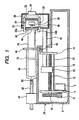
- Support frames 4 and 14 are fixed to a frame 2.
- a drive motor 6 is mounted on the support frame 4, and a pinion gear 8 is mounted on the output shaft of the drive motor 6.
- the support frames 4 and 14 rotatably support a lead screw 12.
- a driven gear 10 is mounted at one end of the lead screw 12, and the driven gear 10 engages with the pinion gear 8.
- a guide rod 16 is movably supported by the frame 2 and the support frame 14.
- a carriage 18 is mounted at one end of the guide rod 16, and the carriage 18 is provided with a nut (not shown) that engages with the lead screw 12.
- the carriage 18 is also provided with an optical sensor 20.
- An linear encoder 22 is fixed to the frame 2, the linear encoder 22 is parallel with the lead screw 12. That is, the carriage 18 is provided with the optical sensor 20, and the linear encoder 22 is disposed to face the optical sensor 20. A slit is formed on the linear encoder 22, thereby allowing the current position of the carriage 18 to be located based on an encoder signal from the optical sensor 20.
- the drive motor 6, the lead screw 12, the carriage 18, etc. compose a plunger mover driver 24 to move a plunger mover 26 (described later).
- the plunger mover 26 to move a plunger 54 (described later) is mounted.
- the plunger mover 26 is provided with a pair of hooks 28a and 28b which are rotatable around a fulcrum 30.
- the bent ends of the hooks 28a and 28b protrude from the plunger mover 26 and have slopes.
- the slope formed at the bent end of the hook 28a and that of the hook 28b face to each other.
- the slopes of the hooks 28a and 28b are outwardly sloped in the direction of pushing the plunger 54 (i.e., to the left in Fig. 1 ).
- the distance between the outside of the slope provided at the bent end of the hook 28a and that of the hook 28b is a little longer than the diameter of a collar 56 (described later).
- a push spring 32 is provided between the hooks 28a and 28b, and the push spring 32 is energized so as to close the hooks 28a and 28b.
- the hooks 28a and 28b are in contact with the plunger mover 26, and the hook 28a and 28b will not rotate in the direction of closing the bent ends of the hooks 28a and 28b.
- the hooks 28a and 28b and the push spring 32 makes up a gripper 76.
- the plunger mover 26 is provided with a release button 34, and the release button 34 has slopes that contact the opposite ends of the bent ends of the hooks 28a and 28b.
- the release button 34 makes up a manual release means to rotate the hooks 28a and 28b against the spring force of the push spring 32.
- a clutch mechanism capable of disengaging the nut from the lead screw 12 is provided. Pushing the release button 34 will actuate the clutch mechanism to disengage the nut within the carriage 18 from the lead screw 12.
- the plunger mover 26 is provided with a plunger grip sensor 36, which has a sensor arm 38.
- a plunger grip sensor chip 40 is supportedbytheplungermover26. These components including the plunger grip sensor 36 make up a plunger grip detecting means to detect whether or not the plunger 54 is gripped.
- a groove 42 is formed on the top of the frame 2, and also a clamp 44 is mounted on the top of the frame 2.
- the clamp 44 contains pin drivers 58a and 58b, which expand and contract direct-driven pins 60a and 60b.
- a flange 48 is provided at one end of a container 46 in which a liquid is contained.
- a liquid delivery portion 50 is provided, to which a liquid delivery channel 52 is connected.
- the plunger 54 is inserted into the container 46, and the plunger 54 has a gasket 78 at one end that is close contact with the inner wall of the container 46.
- a collar 56 is provided at the other end of the plunger 54.
- FIG. 3 the control device of the extrusion-type liquid delivery apparatus shown in Fig. 1 and Fig. 2 will be described.
- An operation/display panel 64, an initial settings input circuit 66, a sensor signal processing circuit 68, a motor drive circuit 70, a positional information processing circuit 72, and clamp drive circuits 74a and 74b are connected to a microprocessor 62.
- the sensor signal processing circuit 68 processes a sensor signal generated by the plunger grip sensor 36.
- the motor drive circuit 70 controls the drive motor 6.
- the positional information processing circuit 72 processes a signal from the optical sensor 20 to obtain positional information about the carriage 18.
- the clamp drive circuits 74a and 74b control the pin drivers 58a and 58b respectively.
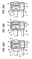
- the microprocessor 62 issues a rotation command to the motor drive circuit 70 to rotate the drive motor 6, which moves the carriage 18 and thereby moves the plunger mover 26 in the direction of arrow M in Fig. 5 (a) .
- the slopes formed at the bent ends of the hooks 28a and 28b contact the edge of the collar 56.
- the hooks 28a and 28b run on the widest portion of the collar 56 against the spring force of the push spring 32, as shown in Fig. 5(b) .
- the microprocessor 62 monitors a grip sensor signal to be input from the plunger grip sensor 36 via the sensor signal processing circuit 68, in order to determine whether the plunger 54 is gripped. Specifically, when the plunger mover 26 is moved in the direction of arrow M from the state in Fig. 5(b) , the collar 56 pushes the plunger grip sensor chip 40 in the opposite direction of arrow M, and the plunger grip sensor chip 40 in turn pushes the sensor arm 38, thereby turning on the plunger grip sensor 36. Therefore, if the microprocessor 62 monitors the output of the plunger grip sensor 36, it is possible to detect whether or not the gripper 76 has gripped the collar 56, namely, the plunger 54. Also, it is possible to obtain an encoder signal from the optical sensor 20, via the positional information processing circuit 72, and to determine the current position of the carriage 18 exactly.
- the microprocessor 62 issues a rotation command to the motor drive circuit 70 to rotate the drive motor 6 and thereby to move the carriage 18, resulting in the plunger 26 moving, in the direction opposite to the direction of arrow M in Fig. 5(a) , i.e., the direction of pushing the plunger 54, by a predetermined distance. That is, the control device moves the plunger mover 26 in the direction opposite to the direction of pushing the plunger 54 by the predetermined distance, after the hooks 28a and 28b of the gripper 76 have gripped the plunger 54.
- a load sensor may be provided so as to face and contact the pushed surface of the collar 56 of the plunger 54, and the microprocessor 62 may monitor the output (a blocking pressure) of the load sensor and move the plunger mover 26 in the direction opposite to the direction of pushing the plunger 54, until the output of the load sensor falls below a prescribed value.
- the microprocessor 62 issues a clamp release command to the clamp drive circuits 74a and 74b to cause the pin drivers 58a and 58b to contract the direct-driven pins 60a and 60b respectively as shown in Fig. 2 , thereby unblocking the liquid delivery channel 52. Then, the microprocessor 62 controls the drive motor 6 via the motor drive circuit 70 to move the plunger mover 26 to the left in Fig. 1 , pushing the plunger 54 into the container 46 to deliver the liquid.
- the operator manually pushes the release button 34 in the direction of arrow P as shown in Fig. 6 .
- This produces a movement to shorten the distance between the rear ends of the hooks 28a and 28b against the force of the push spring 32, and thereby to rotate the hooks 28a and 28b around the fulcrum 30, and consequently the bent ends of the hooks 28a and 28b spread out to release the collar 56.
- the clutch mechanism is actuated to disengage the nut in the carriage 18 from the lead screw 12, allowing the plunger mover 26 to be moved manually.
- the hooks 28a and 28b automatically rotate to grip the collar 56, simply by moving the plunger mover 26 and the gripper 76, and therefore the operator can perform the mounting of the container 46 containing a liquid and the gripping the plunger 54 with a plurality of liquid delivery apparatuses in a short period of time. Also, since there is no need to add a special actuator for automatic gripping, the structure is simple and manufacturing cost can be reduced. Moreover, moving the plunger mover 26 in the direction opposite to arrow P, with the release button 34 pushed in the arrow P direction, will release the collar 56 from the hooks 28a and 28b, and also allows the plunger mover 26 to move to the point where a liquid delivery starts.
- a stepping motor or DC motor can be employed.
- a magnetic position detector can be used.
- an optical or magnetic rotary encoder can be provided at the end of the lead screw 12, as a position detecting means to detect the position of the carriage 18.
- a plunger mover driver having a linear motor can be used for this purpose.
- the plunger grip sensor 36 is used as a plunger grip detecting means in the above embodiment, a magnetic proximity switch or a load sensor that faces and contacts the collar 56 can be used as a plunger grip detecting means.
- other springs can be used instead of the push spring 32 used in the above embodiment, to close the bent ends of the hooks 28a and 28b by spring force.
- the extrusion-type liquid delivery apparatus can be used for applications that require automatic gripping of a plunger which is enabled with a simple construction, such as a medical syringe pump to deliver a liquid contained beforehand with a plunger.
Landscapes
- Health & Medical Sciences (AREA)
- Vascular Medicine (AREA)
- Engineering & Computer Science (AREA)
- Anesthesiology (AREA)
- Biomedical Technology (AREA)
- Heart & Thoracic Surgery (AREA)
- Hematology (AREA)
- Life Sciences & Earth Sciences (AREA)
- Animal Behavior & Ethology (AREA)
- General Health & Medical Sciences (AREA)
- Public Health (AREA)
- Veterinary Medicine (AREA)
- Infusion, Injection, And Reservoir Apparatuses (AREA)
Claims (5)
- Appareil de délivrance de liquide de type extrusion, où un liquide dans un contenant (46) ayant une portion de délivrance de liquide (50) à une extrémité du contenant est extrudé par un plongeur (54) qui est inséré depuis l'autre extrémité du contenant, comprenant:a) un organe de déplacement de plongeur (26) pour déplacer ledit plongeur;b) un organe d'entraînement en déplacement de plongeur (6) pour déplacer ledit organe de déplacement de plongeur;c) deux crochets (28a, 28b) montés en rotation sur ledit organe de déplacement de plongeur avec des extrémités courbées, et ayant des inclinaisons auxdites extrémités courbées; etd) un ressort (32) pour fermer lesdites extrémités courbées des deux crochets par une force de ressort,caractérisé en ce que l'appareil comprend en outre un organe de serrage pour bloquer un canal de délivrance de liquide relié audit contenant, et en ce que lesdites extrémités courbées font saillie dudit organe de déplacement de plongeur où, lorsque ledit organe de déplacement de plongeur se déplace, lesdites inclinaisons viennent en contact avec le bord du collier dudit plongeur, lesdits crochets s'étendent sur la portion la plus large dudit collier contre la force dudit ressort, lesdits crochets passent par-dessus ledit collier et lesdites extrémités courbées saisissent automatique ledit collier par la force dudit ressort.
- Appareil de délivrance de liquide de type extrusion selon la revendication 1, comprenant en outre un moyen de relâchement manuel (34) pour faire tourner lesdits crochets contre la force dudit ressort.
- Appareil de délivrance de liquide de type extrusion selon la revendication 1, comprenant en outre un moyen de détection de prise de plongeur (36) pour détecter si oui ou non ledit plongeur est pris.
- Appareil de délivrance de liquide de type extrusion selon la revendication 1, comprenant en outre un moyen pour diminuer la pression interne dudit contenant après que lesdits crochets ont saisi ledit plongeur.
- Appareil de délivrance de liquide de type extrusion selon la revendication 4, comprenant en outre un dispositif de commande (62) pour déplacer ledit organe de déplacement de plongeur sur une distance prédéterminée dans la direction opposée à la direction de poussée dudit plongeur après que lesdits crochets ont saisi ledit plongeur.
Applications Claiming Priority (4)
| Application Number | Priority Date | Filing Date | Title |
|---|---|---|---|
| JP2004110047A JP4456403B2 (ja) | 2004-04-02 | 2004-04-02 | 送液装置 |
| JP2004110047 | 2004-04-02 | ||
| JP2004317991A JP2006122572A (ja) | 2004-11-01 | 2004-11-01 | 把持制御装置 |
| JP2004317991 | 2004-11-01 |
Publications (2)
| Publication Number | Publication Date |
|---|---|
| EP1588729A1 EP1588729A1 (fr) | 2005-10-26 |
| EP1588729B1 true EP1588729B1 (fr) | 2008-11-05 |
Family
ID=34940696
Family Applications (1)
| Application Number | Title | Priority Date | Filing Date |
|---|---|---|---|
| EP05252088A Expired - Lifetime EP1588729B1 (fr) | 2004-04-02 | 2005-04-01 | Système de délivrance de liquide de type extrusion |
Country Status (3)
| Country | Link |
|---|---|
| US (1) | US20050220639A1 (fr) |
| EP (1) | EP1588729B1 (fr) |
| DE (1) | DE602005010778D1 (fr) |
Families Citing this family (31)
| Publication number | Priority date | Publication date | Assignee | Title |
|---|---|---|---|---|
| DE102004031674B3 (de) * | 2004-06-30 | 2005-08-04 | Erbe Elektromedizin Gmbh | Medizinische Pumpe |
| DE102004031673B4 (de) * | 2004-06-30 | 2009-04-16 | Erbe Elektromedizin Gmbh | Medizinische Pumpe |
| US7798711B2 (en) | 2004-07-27 | 2010-09-21 | Cdf Corporation | Flexible liner for FIBC or bag-in-box container systems |
| US8075188B2 (en) | 2006-02-24 | 2011-12-13 | Cdf Corporation | Flexible liner for FIBC or bag-in-box container systems with improved flex crack resistance |
| US8182152B2 (en) | 2006-03-28 | 2012-05-22 | Cdf Corporation | Flexible liner for FIBC or bag-in-box container systems with improved tensile strength |
| DE102006053609A1 (de) * | 2006-11-14 | 2008-05-15 | Erbe Elektromedizin Gmbh | Medizinische Pumpe |
| US9016555B2 (en) | 2007-04-03 | 2015-04-28 | Cdf Corporation | Flexible liner and bag-in-box container systems |
| AU2013202242B2 (en) * | 2007-04-13 | 2014-09-11 | Covidien Lp | Powered surgical instrument |
| US11259802B2 (en) | 2007-04-13 | 2022-03-01 | Covidien Lp | Powered surgical instrument |
| US7950560B2 (en) | 2007-04-13 | 2011-05-31 | Tyco Healthcare Group Lp | Powered surgical instrument |
| US20080255413A1 (en) | 2007-04-13 | 2008-10-16 | Michael Zemlok | Powered surgical instrument |
| US20080310766A1 (en) * | 2007-06-13 | 2008-12-18 | James Plunkett | Liner with bladder |
| US8567660B2 (en) | 2009-11-17 | 2013-10-29 | Cdf Corporation | Sustainable packaging system for shipping liquid or viscous products |
| US9120608B2 (en) | 2009-11-17 | 2015-09-01 | Cdf Corporation | Sustainable packaging system for shipping liquid or viscous products |
| US9295778B2 (en) * | 2011-12-21 | 2016-03-29 | Deka Products Limited Partnership | Syringe pump |
| US9744300B2 (en) | 2011-12-21 | 2017-08-29 | Deka Products Limited Partnership | Syringe pump and related method |
| US9789247B2 (en) * | 2011-12-21 | 2017-10-17 | Deka Products Limited Partnership | Syringe pump, and related method and system |
| WO2012068208A1 (fr) | 2010-11-16 | 2012-05-24 | Cdf Corporation | Système d'emballage secondaire pour produits pré-emballés |
| EP2500050A1 (fr) * | 2011-03-16 | 2012-09-19 | Fresenius Kabi Deutschland GmbH | Tête motrice pour pompe de seringue et procédé de fonctionnement d'une tête motrice |
| US10563681B2 (en) | 2011-12-21 | 2020-02-18 | Deka Products Limited Partnership | System, method, and apparatus for clamping |
| US10722645B2 (en) | 2011-12-21 | 2020-07-28 | Deka Products Limited Partnership | Syringe pump, and related method and system |
| US12131826B2 (en) | 2011-12-21 | 2024-10-29 | Deka Products Limited Partnership | Syringe pump and related method |
| US11217340B2 (en) | 2011-12-21 | 2022-01-04 | Deka Products Limited Partnership | Syringe pump having a pressure sensor assembly |
| CN104487113B (zh) | 2012-12-28 | 2017-07-14 | 甘布罗伦迪亚股份公司 | 注射泵接合检测设备和方法 |
| DE102013004860B3 (de) | 2013-03-21 | 2014-09-04 | Fresenius Medical Care Deutschland Gmbh | Vorrichtung zur Aufnahme einer Spritze in eine Fluidabgabevorrichtung sowie Verfahren hierzu und Verwendung einer solchen Aufnahme |
| AU2015218864B2 (en) | 2014-02-21 | 2019-10-03 | Deka Products Limited Partnership | Syringe pump having a pressure sensor assembly |
| MX392620B (es) * | 2015-01-26 | 2025-03-24 | Becton Dickinson Co | Dispositivo de captura de dosis para jeringas. |
| US10589022B2 (en) * | 2015-12-30 | 2020-03-17 | Baxter Corporation Englewood | Syringe plunger positioning apparatus and method |
| US10843824B2 (en) * | 2015-12-30 | 2020-11-24 | Baxter International Inc. | Syringe positioning apparatus and method |
| US11441550B2 (en) * | 2018-06-29 | 2022-09-13 | Norgren Kloehn Llc | Self-aligning power screw for syringe pump |
| WO2020021056A1 (fr) * | 2018-07-27 | 2020-01-30 | CSL Behring Lengnau AG | Dispositif de perfusion doté d'un mécanisme de préhension |
Family Cites Families (8)
| Publication number | Priority date | Publication date | Assignee | Title |
|---|---|---|---|---|
| US4544369A (en) * | 1983-11-22 | 1985-10-01 | C. R. Bard, Inc. | Battery operated miniature syringe infusion pump |
| US4838857A (en) * | 1985-05-29 | 1989-06-13 | Becton, Dickinson And Company | Medical infusion device |
| FR2625102B1 (fr) * | 1987-12-24 | 1994-06-10 | Godefroy Alain | Perfectionnement aux pousse-seringues universels |
| US6428509B1 (en) * | 1999-07-29 | 2002-08-06 | Alaris Medical Systems, Inc. | Syringe plunger driver system and method |
| JP3933832B2 (ja) * | 1999-12-24 | 2007-06-20 | テルモ株式会社 | シリンジポンプ |
| US7150724B2 (en) * | 2002-06-05 | 2006-12-19 | Cardinal Health 303, Inc. | Syringe plunger driver system |
| JP2004065736A (ja) * | 2002-08-08 | 2004-03-04 | Nemoto Kyorindo:Kk | 薬液注入装置 |
| JP4286019B2 (ja) * | 2003-02-04 | 2009-06-24 | 株式会社根本杏林堂 | 薬液注入システム |
-
2005
- 2005-03-31 US US11/094,277 patent/US20050220639A1/en not_active Abandoned
- 2005-04-01 EP EP05252088A patent/EP1588729B1/fr not_active Expired - Lifetime
- 2005-04-01 DE DE602005010778T patent/DE602005010778D1/de not_active Expired - Lifetime
Also Published As
| Publication number | Publication date |
|---|---|
| DE602005010778D1 (de) | 2008-12-18 |
| EP1588729A1 (fr) | 2005-10-26 |
| US20050220639A1 (en) | 2005-10-06 |
Similar Documents
| Publication | Publication Date | Title |
|---|---|---|
| EP1588729B1 (fr) | Système de délivrance de liquide de type extrusion | |
| EP1723978B1 (fr) | Système de propulsion pour des tiges de piston de seringues | |
| CA2176473C (fr) | Pompe de perfusion pour seringue possedant un detecteur de plongeur de seringue | |
| EP1679091B1 (fr) | Pompe seringue | |
| EP2606922B1 (fr) | Pompe à perfusion avec dispositif d'entraînement et dispositif the blocage d'une tête d'entraînement de piston de seringue | |
| JP5764661B2 (ja) | 薬剤注入装置 | |
| CN116723876B (zh) | 输液泵及输液泵的控制方法 | |
| WO1998030260A1 (fr) | Appareil de transport de liquides | |
| CN102266602B (zh) | 注射系统的实时检测机构及具有这种机构的注射系统 | |
| JP4456403B2 (ja) | 送液装置 | |
| CN113474023B (zh) | 用于向患者施用医用流体的输注装置 | |
| JP4679984B2 (ja) | 把持検知装置 | |
| AU2007203388B2 (en) | Syringe plunger driver system | |
| CN121944294A (zh) | 具有制动装置的输注装置 | |
| KR20240157688A (ko) | 주입 전달 장치 | |
| JP6508931B2 (ja) | 液体送り出し駆動装置 | |
| HK1099717B (en) | Syringe plunger driver system | |
| JP2006122572A (ja) | 把持制御装置 | |
| HK1076060B (en) | Syringe plunger driver system | |
| GB2420719A (en) | A syringe pump and pusher mechanism |
Legal Events
| Date | Code | Title | Description |
|---|---|---|---|
| PUAI | Public reference made under article 153(3) epc to a published international application that has entered the european phase |
Free format text: ORIGINAL CODE: 0009012 |
|
| AK | Designated contracting states |
Kind code of ref document: A1 Designated state(s): AT BE BG CH CY CZ DE DK EE ES FI FR GB GR HU IE IS IT LI LT LU MC NL PL PT RO SE SI SK TR |
|
| AX | Request for extension of the european patent |
Extension state: AL BA HR LV MK YU |
|
| 17P | Request for examination filed |
Effective date: 20051230 |
|
| AKX | Designation fees paid |
Designated state(s): DE GB |
|
| GRAP | Despatch of communication of intention to grant a patent |
Free format text: ORIGINAL CODE: EPIDOSNIGR1 |
|
| GRAS | Grant fee paid |
Free format text: ORIGINAL CODE: EPIDOSNIGR3 |
|
| GRAA | (expected) grant |
Free format text: ORIGINAL CODE: 0009210 |
|
| AK | Designated contracting states |
Kind code of ref document: B1 Designated state(s): DE GB |
|
| REG | Reference to a national code |
Ref country code: GB Ref legal event code: FG4D |
|
| REF | Corresponds to: |
Ref document number: 602005010778 Country of ref document: DE Date of ref document: 20081218 Kind code of ref document: P |
|
| PLBE | No opposition filed within time limit |
Free format text: ORIGINAL CODE: 0009261 |
|
| STAA | Information on the status of an ep patent application or granted ep patent |
Free format text: STATUS: NO OPPOSITION FILED WITHIN TIME LIMIT |
|
| 26N | No opposition filed |
Effective date: 20090806 |
|
| PGFP | Annual fee paid to national office [announced via postgrant information from national office to epo] |
Ref country code: GB Payment date: 20100325 Year of fee payment: 6 |
|
| PGFP | Annual fee paid to national office [announced via postgrant information from national office to epo] |
Ref country code: DE Payment date: 20100430 Year of fee payment: 6 |
|
| GBPC | Gb: european patent ceased through non-payment of renewal fee |
Effective date: 20110401 |
|
| PG25 | Lapsed in a contracting state [announced via postgrant information from national office to epo] |
Ref country code: DE Free format text: LAPSE BECAUSE OF NON-PAYMENT OF DUE FEES Effective date: 20111101 |
|
| PG25 | Lapsed in a contracting state [announced via postgrant information from national office to epo] |
Ref country code: GB Free format text: LAPSE BECAUSE OF NON-PAYMENT OF DUE FEES Effective date: 20110401 |
|
| REG | Reference to a national code |
Ref country code: DE Ref legal event code: R119 Ref document number: 602005010778 Country of ref document: DE Effective date: 20111101 |