EP1588742B1 - Appareil d'entraînement - Google Patents
Appareil d'entraînement Download PDFInfo
- Publication number
- EP1588742B1 EP1588742B1 EP05007649A EP05007649A EP1588742B1 EP 1588742 B1 EP1588742 B1 EP 1588742B1 EP 05007649 A EP05007649 A EP 05007649A EP 05007649 A EP05007649 A EP 05007649A EP 1588742 B1 EP1588742 B1 EP 1588742B1
- Authority
- EP
- European Patent Office
- Prior art keywords
- training device
- generator
- shaft
- display
- sensors
- Prior art date
- Legal status (The legal status is an assumption and is not a legal conclusion. Google has not performed a legal analysis and makes no representation as to the accuracy of the status listed.)
- Expired - Lifetime
Links
- 230000001419 dependent effect Effects 0.000 claims description 5
- 238000006073 displacement reaction Methods 0.000 claims description 4
- 239000007788 liquid Substances 0.000 claims description 2
- 239000004065 semiconductor Substances 0.000 claims description 2
- 238000007493 shaping process Methods 0.000 claims description 2
- 238000006243 chemical reaction Methods 0.000 claims 1
- 210000003205 muscle Anatomy 0.000 claims 1
- 230000033001 locomotion Effects 0.000 abstract description 9
- 238000010586 diagram Methods 0.000 description 4
- 238000005452 bending Methods 0.000 description 3
- 230000005540 biological transmission Effects 0.000 description 3
- 239000013078 crystal Substances 0.000 description 2
- 239000012530 fluid Substances 0.000 description 2
- 230000003287 optical effect Effects 0.000 description 2
- 230000001960 triggered effect Effects 0.000 description 2
- 235000014676 Phragmites communis Nutrition 0.000 description 1
- 230000000903 blocking effect Effects 0.000 description 1
- 239000003990 capacitor Substances 0.000 description 1
- 238000004891 communication Methods 0.000 description 1
- 230000008878 coupling Effects 0.000 description 1
- 238000010168 coupling process Methods 0.000 description 1
- 238000005859 coupling reaction Methods 0.000 description 1
- 238000001514 detection method Methods 0.000 description 1
- 238000005265 energy consumption Methods 0.000 description 1
- 230000003387 muscular Effects 0.000 description 1
- 230000001681 protective effect Effects 0.000 description 1
Images

Classifications
-
- A—HUMAN NECESSITIES
- A63—SPORTS; GAMES; AMUSEMENTS
- A63B—APPARATUS FOR PHYSICAL TRAINING, GYMNASTICS, SWIMMING, CLIMBING, OR FENCING; BALL GAMES; TRAINING EQUIPMENT
- A63B21/00—Exercising apparatus for developing or strengthening the muscles or joints of the body by working against a counterforce, with or without measuring devices
- A63B21/005—Exercising apparatus for developing or strengthening the muscles or joints of the body by working against a counterforce, with or without measuring devices using electromagnetic or electric force-resisters
- A63B21/0053—Exercising apparatus for developing or strengthening the muscles or joints of the body by working against a counterforce, with or without measuring devices using electromagnetic or electric force-resisters using alternators or dynamos
-
- A—HUMAN NECESSITIES
- A63—SPORTS; GAMES; AMUSEMENTS
- A63B—APPARATUS FOR PHYSICAL TRAINING, GYMNASTICS, SWIMMING, CLIMBING, OR FENCING; BALL GAMES; TRAINING EQUIPMENT
- A63B21/00—Exercising apparatus for developing or strengthening the muscles or joints of the body by working against a counterforce, with or without measuring devices
- A63B21/00058—Mechanical means for varying the resistance
- A63B21/00069—Setting or adjusting the resistance level; Compensating for a preload prior to use, e.g. changing length of resistance or adjusting a valve
-
- A—HUMAN NECESSITIES
- A63—SPORTS; GAMES; AMUSEMENTS
- A63B—APPARATUS FOR PHYSICAL TRAINING, GYMNASTICS, SWIMMING, CLIMBING, OR FENCING; BALL GAMES; TRAINING EQUIPMENT
- A63B21/00—Exercising apparatus for developing or strengthening the muscles or joints of the body by working against a counterforce, with or without measuring devices
- A63B21/008—Exercising apparatus for developing or strengthening the muscles or joints of the body by working against a counterforce, with or without measuring devices using hydraulic or pneumatic force-resisters
- A63B21/0083—Exercising apparatus for developing or strengthening the muscles or joints of the body by working against a counterforce, with or without measuring devices using hydraulic or pneumatic force-resisters of the piston-cylinder type
-
- A—HUMAN NECESSITIES
- A63—SPORTS; GAMES; AMUSEMENTS
- A63B—APPARATUS FOR PHYSICAL TRAINING, GYMNASTICS, SWIMMING, CLIMBING, OR FENCING; BALL GAMES; TRAINING EQUIPMENT
- A63B24/00—Electric or electronic controls for exercising apparatus of preceding groups; Controlling or monitoring of exercises, sportive games, training or athletic performances
Definitions
- the invention relates to a training device with a lever which opposes its actuation by means of muscular force an adjustable resistance and is rotatably connected with its one end to a shaft which meshes via a toothing with a rack which moves a double-acting displacer in a working cylinder, the liquid-filled work spaces are connected via lines and adjustable valves, and with sensors that convert actuation-dependent mechanical variables into electrical signals that are processed in an electrical circuit powered by a power source and displayed on a display.
- Such a training device which is suitable both for increasing the physical fitness as well as in the context of rehabilitation measures after illness or accident, is in several, the training of different areas of the human musculoskeletal adapted embodiments, for example EP 0 275 956 A2 known.
- the latter comprise handgrips or footrests arranged in accordance with the respective intended use, which are connected via coupling links to the lever acting on the shaft.
- the training device generates a constant, but speed-dependent resistance over the entire actuation path, both during the stretching and during the bending movement.
- a stretching movement causes a rotation of the shaft in one direction, a bending movement in the opposite direction.
- the reversing rotation of the shaft is converted into an alternating displacement of the working piston.
- Each direction is a flow resistance in assigned to the relevant line determining valve. Therefore, the resistance to be overcome by the user in the two directions of movement can be set to be different in size.
- the known device has sensors by means of which the number of reversing rotations of the shaft, ie the number of stretching and bending movements of the user and the settings of the two valves determined in accordance with the in each direction of movement to be overcome by the user resistance of the device and together with the elapsed Training or use time are displayed as dimensionless numbers on the display.
- a power source is a rechargeable battery
- mains voltage increased safety requirements and accordingly a decrease and approval of the device by the competent authorities is required
- power cables affect the mobility of the training device and are generally disturbing, especially if multiple training devices different embodiment in a training center are used spatially close.
- the feeding of the sensors, the electrical circuit and the display from a battery has the disadvantage that the battery from the mains via a charger must be recharged regularly, which often takes several hours and only outside the periods of use, eg at night , is possible.
- the invention has for its object to provide a training device of the type mentioned in the introduction, which manages permanently without external power source.
- the invention is based on the initially surprising finding that in this way the power requirement of the electrical components of the training device can cover, although the shaft rotates reversely only by an angle of rarely more than 90 ° and at a relatively low angular velocity.
- the generator is a stepper motor with downstream rectification. Suitable stepper motor types are commercially available and therefore much cheaper than a custom-made generator.
- the shaft drives the generator via a transmission gear (claim 2).
- the gear can consist of a simple Stirntechnik scholar juxtapos.
- a multi-stage gear transmission or a toothed belt transmission can be used.
- the current source can consist of a single rechargeable cell with a downstream boost converter, because the efficiency of the stepper motor operated as a generator has been shown to be much better at the low charging voltage of a standard 1.2V rechargeable cell than at the charging voltage for e.g. is three cells connected in series.
- the shaft may be associated with a motion sensor, such as a simple electromechanical contact such as a non-contact switching reed switch, whose switching cycles after processing in the electrical circuit on the display numerically or graphically can be represented as a number of stretching and Beugeschulen or strokes.
- a motion sensor such as a simple electromechanical contact such as a non-contact switching reed switch, whose switching cycles after processing in the electrical circuit on the display numerically or graphically can be represented as a number of stretching and Beugeschulen or strokes.
- the shaft is associated with a rotary encoder whose output signals in the electrical circuit be processed (claim 3), in which case in addition, the amplitude per stroke can be reproduced on the display.
- such a rotary encoder can consist of two mutually staggered sensors, which act on a pattern moving in synchronism with the shaft, e.g. an optical pattern, responsive and provide electrical signals in a conventional manner, from which can be determined both the rotation angle and the direction of rotation.
- the two sensors of the rotary encoder can be Hall sensors which are arranged opposite the teeth of a gear rotatably connected to the shaft offset by half a pitch step or an odd multiple thereof.
- Hall sensors have opposite to other sensors, e.g. optical sensors, the advantage of a much lower energy consumption.
- each valve can be assigned a valve position sensor (claim 5).
- the output signals of the valve position sensors are representative of the amount of resistance that the user of the training device must overcome and therefore can also be processed in the electrical circuit and displayed numerically or graphically in the display.
- the respective valve position sensor may in particular be an electromechanical incremental encoder (claim 6), which has the advantage that it consumes almost no electrical power.
- the resistance to be overcome by the user of the training device in the direction of movement can be determined by pressure sensors which convert the pressure in each of the working chambers of the working cylinder into a proportional electrical signal.
- the pressure sensors cause a higher consumption of electrical power than the incremental encoder.
- the electrical circuit comprises a microprocessor which calculates usage-dependent variables for display on the display from the output signals of the sensors (claim 7).
- this microprocessor from the output signals of the sensors can calculate the work spent by the user and the power generated by him and on the Display bring to display (claim 8).
- the required algorithm is relatively easy to program in the microprocessor.
- the calibration of the indications on the display, eg in watt-hours and watts, is empirically possible with sufficient accuracy.
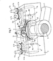
- FIG. 1 shows the assembly which is common to all embodiments of the exerciser, which generates the resistance which the user can activate by actuating e.g. of footrests or hand levers.
- a lever 1 is rotatably connected to a shaft 2, which is mounted in a housing 3.
- the shaft is spur-toothed in the manner of a pinion. With this toothing 4, the shaft meshes with a rack 5 on the circumference of a double-acting displacer 6.
- the displacer 6 is displaceable in a working cylinder, which has on both sides of the displacer 6 each have a working space 7a and 7b.
- the working space 7a is connected via a line 8a and the working space 7b via a line 8b to a chamber 9, which in turn communicates with channels 6a and 6b extending in the central axis of the displacer 6, via check valves 10a and 10b into the corresponding working spaces 7a and 7b 7b opens.
- the line 8a is guided via a valve 11a, the opening cross-section of which the user of the training device can change by turning on or turning off a valve body 11.1a.
- In the train of the line 8b is a similar valve 11b with rotatable valve body 11.1b. All rooms and lines are filled with a hydraulic fluid.
- the user for the two directions of rotation of the shaft 2 according to the two directions of displacement of the displacer 6 set the resistance different that the displacer 6 must overcome to displace the hydraulic fluid from the respective working space.
- a spur gear 20 with eg 100 teeth, which meshes with a pinion 21 with, for example, 20 teeth.
- the pinion 21 is non-rotatably mounted on the shaft of a stepping motor 22, which is used here as a generator.
- the electrical connections of the stepping motor 22 are shown only schematically.
- two Hall sensors 23a and 23b are arranged offset by 1 1/2 pitch steps in the circumferential direction of the spur gear 20.
- the Hall sensors 23a, 23b are used in a conventional manner to determine the direction of rotation and the angle of rotation of the spur gear 20 and thus the shaft 2.
- the electrical connections of the Hall sensors 23a, 23b are indicated schematically.
- Each of the rotatable valve body 11.1a and 11.1b carries a small gear 11.11a and 11.11b, the tooth width is sufficiently dimensioned that it always in engagement with a gear 24.1a and 24.1b of an incremental encoder despite the axial displacement upon rotation of the respective valve body 24a or 24b remains.
- the incremental encoders 24a, 24b are designed as electromechanical switch contacts. Their connections are indicated schematically. Each incremental encoder generates e.g. each rotation of the respective valve member by 15 ° a pulse.
- the other electrical components of the training device in particular the battery, the microprocessor and the display are arranged elsewhere in the device. Their function will be explained below with reference to FIG.
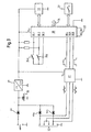
- the circuit comprises a microprocessor 30, to which a power-saving graphics display 31 and an input keypad 32 and a crystal oscillator 33 for generating the internal time base of the microprocessor 30 are connected.
- a microprocessor 30 For example, predefined programs or the display mode of the graphic display can be called up, a time display can be started or other functions can be triggered via the keys of the input keypad 32.
- V cc of, for example, 3.3 volts
- the microprocessor 30 obtains from a rechargeable battery 35 via a voltage regulator 36.
- the battery is rechargeable via an external terminal 37 and a protection diode 38.
- the battery is charged via the stepper motor 22 which operates as a generator. Since the stepping motor supplies an alternating voltage at its line connections in the case of its operation as a generator, the battery 35 is connected via the diodes 39a and 39b to the corresponding line connections.
- the microprocessor 30 receives at its terminals 30.1, 30.2 and 30.3, the pulses of the incremental 24a and 24b and at its terminals 30.4 and 30.5, the output signals of the Hall sensors 23a and 23b, which are processed and amplified respectively in only schematically illustrated amplifier circuits 40a, 40b. As long as there are no pulses at its terminals 30.4 and 30.5, the microprocessor 30 is in a power-saving standby state and turns off the display 31.
- the Hall sensors and their amplifier circuits require a supply current of a few milliamperes. Therefore, they are not connected directly but via a MOSFET 41 to the battery 35.
- the MOSFET 41 is in an unused training device in the blocking state, because its gate is connected to the ground potential via the resistor R. However, the gate of the MOSFET 41 is connected via a capacitor C and the indicated rectifier circuit to one of the AC voltage outputs of the stepper motor 22 operated as a generator.
- the MOSFET 41 immediately transmits at the beginning of the operation of the exerciser, so that the Hall sensors 23a and 23b receive their supply voltage V 1cc and 2 pulses according to the rotation of the wave supply to the inputs 30.4 and 30.5 of the microprocessor 30, which then from its standby - goes into its operating state and carries out the programmed processing of the input signals. If necessary, you can Other components with high quiescent current consumption also their power via the MOSFET 41 instead of directly from the battery 35 relate.
- FIG 3 shows the block diagram of an embodiment of the training device with the same mechanical components as in Figure 1, but without the Hall sensors 23a, 23b shown there.
- the circuit comprises a microprocessor 30, to which a power-saving graphics display 31, an input keypad 32, a crystal oscillator 33 for generating the internal time base of the microprocessor 30 are connected.
- a microprocessor 30 By way of the keys of the input keypad 32, e.g. preset programs or the display mode of the graphic display, a time display is started or other functions are triggered.
- the microprocessor 30 has a programming and communication interface 34.
- the microprocessor 30 receives at its terminals 30.1, 30.2 and 30.3, the pulses of the incremental encoder 24a and 24b and at its terminals 30.4, 30.5 and 30.6 the rectangular output signals of a pulse shaping circuit 47, at the inputs of which supplied by the two phase coils of the stepping motor 22, phase-shifted output voltages , From the relative phase of the rectangular pulses of the microprocessor determines the direction of rotation of the shaft 2 in Figure 1 and from the number of pulses per direction of rotation the angle of rotation.
- Both the microprocessor 30 and the pulse shaper circuit 47 draw their operating voltage V cc of, for example, 3.3 volts via a boost converter 45 from a single 1.2 V rechargeable cell 46.
- the cell is for initial charging or recharging after a long period of non-use Chargeable via an external terminal 48 and a protective diode 49.
- the cell is charged via the stepper motor 22 which operates as a generator. Whose strand connections are connected in series and load via the diodes 50a and 50b, the cell 46th
Landscapes
- Health & Medical Sciences (AREA)
- General Health & Medical Sciences (AREA)
- Physical Education & Sports Medicine (AREA)
- Life Sciences & Earth Sciences (AREA)
- Biophysics (AREA)
- Orthopedic Medicine & Surgery (AREA)
- Physics & Mathematics (AREA)
- Electromagnetism (AREA)
- Rehabilitation Tools (AREA)
- Pharmaceuticals Containing Other Organic And Inorganic Compounds (AREA)
- Connection Of Motors, Electrical Generators, Mechanical Devices, And The Like (AREA)
Claims (9)
- Appareil de musculation avec un levier (1) dont l'actionnement au moyen d'une force musculaire rencontre une résistance réglable et qui est pour cela relié de manière solidaire en rotation à un arbre (2) engrenant par une denture (4) avec une crémaillère (5) qui est disposée avec possibilité de translation sur un piston de refoulement (6) à double action d'un vérin de travail, dont les compartiments de travail (7a, 7b) remplis de liquide communiquent par des conduites (8a, 8b ; 6a, 6b) et des soupapes (11a, 11b) réglables, et avec des capteurs destinés à transformer des grandeurs mécaniques dépendantes de l'actionnement en signaux électriques, avec un circuit électrique alimenté par une source de courant (35) pour traiter ces signaux et avec un afficheur (31) pour l'affichage de ces signaux sous la forme de valeurs, caractérisé en ce que l'arbre (2) est couplé en vue du chargement de la source de courant à un générateur électrique (22), lequel générateur est un moteur pas-à-pas (22) suivi d'un circuit redresseur (39a, 39b).
- Appareil de musculation selon la revendication l, caractérisé en ce que l'arbre (2) est couplé au générateur (22) par un engrenage multiplicateur (20, 21).
- Appareil de musculation selon la revendication 1 ou 2, caractérisé en ce que l'arbre (2) est associé à un capteur d'angle de rotation (23a, 23b) dont les signaux de sortie peuvent être traités dans le circuit électrique.
- Appareil de musculation selon l'une des revendications 1 à 3, caractérisé en ce que chacun des deux signaux de sortie approximativement sinusoïdaux des faisceaux du moteur pas-à-pas (22) peut être converti en impulsions carrées dans un circuit conformateur d'impulsions (47) et en ce que la comparaison de leur phase permet de déterminer le sens de rotation et le comptage des impulsions l'angle de rotation de l'arbre (2).
- Appareil de musculation selon l'une des revendications 1 à 4, caractérisé en ce que chaque soupape (11a, 11b) est associée à un capteur de position de soupape (24a, 24b).
- Appareil de musculation selon la revendication 5, caractérisé en ce que le capteur de position de soupape est un capteur incrémentiel (24a, 24b) électromécanique.
- Appareil de musculation selon l'une des revendications 1 à 6, caractérisé en ce que le circuit électrique comprend un microprocesseur (30) qui est apte à calculer à partir des signaux de sortie des capteurs (23a, 23b, 24a, 24b) des grandeurs dépendantes de l'utilisation destinées à être affichées sur l'afficheur (31).
- Appareil de musculation selon la revendication 7, caractérisé en ce que le microprocesseur (30) est apte à calculer à partir des signaux de sortie des capteurs (23a, 23b, 24a, 24b) l'effort fourni par l'utilisateur et la force développée par celui-ci en vue de leur affichage sur l'afficheur (31).
- Appareil de musculation selon l'une des revendications 3 à 8, caractérisé en ce que le capteur d'angle de rotation (23a, 40a ; 23b, 40b) reçoit sa tension d'alimentation (Vloc) de la source de courant (35) par l'intermédiaire d'un commutateur à semi-conducteurs contrôlé (41), dont l'entrée de commande est reliée à une sortie du générateur (22) et qui devient passant dès que le générateur délivre une tension à ses sorties.
Applications Claiming Priority (4)
| Application Number | Priority Date | Filing Date | Title |
|---|---|---|---|
| DE102004019328 | 2004-04-21 | ||
| DE102004019328A DE102004019328B3 (de) | 2004-04-21 | 2004-04-21 | Trainingsgerät |
| DE102004051371A DE102004051371A1 (de) | 2004-04-21 | 2004-10-21 | Trainingsgerät |
| DE102004051371 | 2004-10-21 |
Publications (2)
| Publication Number | Publication Date |
|---|---|
| EP1588742A1 EP1588742A1 (fr) | 2005-10-26 |
| EP1588742B1 true EP1588742B1 (fr) | 2007-08-29 |
Family
ID=34934859
Family Applications (1)
| Application Number | Title | Priority Date | Filing Date |
|---|---|---|---|
| EP05007649A Expired - Lifetime EP1588742B1 (fr) | 2004-04-21 | 2005-04-07 | Appareil d'entraînement |
Country Status (3)
| Country | Link |
|---|---|
| EP (1) | EP1588742B1 (fr) |
| AT (1) | ATE371477T1 (fr) |
| DE (2) | DE102004051371A1 (fr) |
Families Citing this family (2)
| Publication number | Priority date | Publication date | Assignee | Title |
|---|---|---|---|---|
| WO2007141760A1 (fr) * | 2006-06-08 | 2007-12-13 | Genesis Fitness (Pty) Ltd | Dispositif d'exercice isocinétique |
| GB201322949D0 (en) * | 2013-12-23 | 2014-02-12 | Scott Steve | An apparatus for physical exercise |
Family Cites Families (6)
| Publication number | Priority date | Publication date | Assignee | Title |
|---|---|---|---|---|
| DE3526144A1 (de) * | 1985-07-22 | 1987-01-29 | Guenter Kern | Trainingsgeraet |
| DE3705493A1 (de) * | 1987-01-22 | 1988-08-04 | Kern Guenter | Medizinisches diagnosegeraet |
| DE3704918A1 (de) * | 1987-02-17 | 1988-08-25 | Kst Motorenversuch Gmbh Co | Ruderergometer |
| DE9313532U1 (de) * | 1993-04-07 | 1993-11-18 | Friedrich, Horst, 4150 Krefeld | Trainingsgerät |
| US5618250A (en) * | 1994-09-02 | 1997-04-08 | Butz; Todd M. | Aerobic exercise machine targeting trunk muscles |
| DE19515597C2 (de) * | 1995-05-02 | 2001-08-30 | Frank Werfel | Verfahren zur Energierückgewinnung an Trainingsgeräten |
-
2004
- 2004-10-21 DE DE102004051371A patent/DE102004051371A1/de not_active Withdrawn
-
2005
- 2005-04-07 EP EP05007649A patent/EP1588742B1/fr not_active Expired - Lifetime
- 2005-04-07 AT AT05007649T patent/ATE371477T1/de not_active IP Right Cessation
- 2005-04-07 DE DE502005001346T patent/DE502005001346D1/de not_active Expired - Fee Related
Also Published As
| Publication number | Publication date |
|---|---|
| ATE371477T1 (de) | 2007-09-15 |
| DE102004051371A1 (de) | 2006-04-27 |
| DE502005001346D1 (de) | 2007-10-11 |
| EP1588742A1 (fr) | 2005-10-26 |
Similar Documents
| Publication | Publication Date | Title |
|---|---|---|
| DE60202408T2 (de) | Greifvorrichtung | |
| EP1349281B1 (fr) | Dispositif de commande pour un appareil électrique | |
| EP0899847B1 (fr) | Procédé pour la détermination de la position et de la direction du mouvement d'une partie mobile entraînée par un moteur électrique | |
| DE2724223C3 (de) | Einrichtung zur Auswertung und Anzeige analoger elektrischer Signale | |
| EP2264875A1 (fr) | Un convertisseur d'énergie électromagnétique et un procédé de conversion d'une énergie mécanique en énergie électrique | |
| DE4233243A1 (de) | Gleichstrommotorantrieb und verfahren zur steuerung desselben | |
| DE3823487A1 (de) | Tuerschliessverfahren und -anordnung | |
| DE102016210600B4 (de) | Vorrichtung zur beeinflussung der öffnungs- und/oder schliessbewegung eines tür- oder fensterflügels | |
| AT515703B1 (de) | Verriegelungsvorrichtung | |
| EP1327860A2 (fr) | Contrôleur à variation continue à fonction cumutatrice | |
| EP2651043B1 (fr) | Dispositif et procédé de transmission d'énergie et de données entre une unité de commande et un appareil de mesure de position | |
| DE10262063A1 (de) | Schnittstelleneinrichtung mit einem Generator elektrischer Energie | |
| DE102013217911A1 (de) | Werkzeugkopf und Bearbeitungszentrum | |
| DE102015226091A1 (de) | Handwerkzeugmaschine mit einem Schlagwerk | |
| DE2148237A1 (de) | Einstellvorrichtung für die Druckfarbenversorgung | |
| EP1462771A2 (fr) | Procédé et appareil pour déterminer la position absolue d'un axe d'un détecteur de position | |
| DE102019109548A1 (de) | Vorrichtung mit zumindest einem Sensor und einem Energiewandler zur Energieversorgung des zumindest einen Sensors | |
| EP1588742A1 (fr) | Appareil d'entraínement | |
| DE102004019328B3 (de) | Trainingsgerät | |
| EP2987225B1 (fr) | Dispositif de communication | |
| DE102004024591B4 (de) | Fernbedienung zur Steuerung der Solltemperatur eines elektrischen Durchlauferhitzers | |
| EP3317738A1 (fr) | Thermostat pour installations de chauffage, climatisation et/ou ventilation | |
| DE10142431A1 (de) | Steuereinrichtung für Schnelllauftore | |
| DE8502372U1 (de) | Messvorrichtung für Trainingsmaschinen | |
| DE1808934C3 (de) | Myoelektrische Steuerschaltung für proportional gesteuerte servomotorisch betätigte Kunstglieder |
Legal Events
| Date | Code | Title | Description |
|---|---|---|---|
| PUAI | Public reference made under article 153(3) epc to a published international application that has entered the european phase |
Free format text: ORIGINAL CODE: 0009012 |
|
| AK | Designated contracting states |
Kind code of ref document: A1 Designated state(s): AT BE BG CH CY CZ DE DK EE ES FI FR GB GR HU IE IS IT LI LT LU MC NL PL PT RO SE SI SK TR |
|
| AX | Request for extension of the european patent |
Extension state: AL BA HR LV MK YU |
|
| 17P | Request for examination filed |
Effective date: 20060223 |
|
| AKX | Designation fees paid |
Designated state(s): AT BE BG CH CY CZ DE DK EE ES FI FR GB GR HU IE IS IT LI LT LU MC NL PL PT RO SE SI SK TR |
|
| GRAP | Despatch of communication of intention to grant a patent |
Free format text: ORIGINAL CODE: EPIDOSNIGR1 |
|
| GRAS | Grant fee paid |
Free format text: ORIGINAL CODE: EPIDOSNIGR3 |
|
| GRAA | (expected) grant |
Free format text: ORIGINAL CODE: 0009210 |
|
| AK | Designated contracting states |
Kind code of ref document: B1 Designated state(s): AT BE BG CH CY CZ DE DK EE ES FI FR GB GR HU IE IS IT LI LT LU MC NL PL PT RO SE SI SK TR |
|
| REG | Reference to a national code |
Ref country code: GB Ref legal event code: FG4D Free format text: NOT ENGLISH |
|
| REG | Reference to a national code |
Ref country code: CH Ref legal event code: EP |
|
| REG | Reference to a national code |
Ref country code: IE Ref legal event code: FG4D Free format text: LANGUAGE OF EP DOCUMENT: GERMAN |
|
| REF | Corresponds to: |
Ref document number: 502005001346 Country of ref document: DE Date of ref document: 20071011 Kind code of ref document: P |
|
| PG25 | Lapsed in a contracting state [announced via postgrant information from national office to epo] |
Ref country code: ES Free format text: LAPSE BECAUSE OF FAILURE TO SUBMIT A TRANSLATION OF THE DESCRIPTION OR TO PAY THE FEE WITHIN THE PRESCRIBED TIME-LIMIT Effective date: 20071210 Ref country code: FI Free format text: LAPSE BECAUSE OF FAILURE TO SUBMIT A TRANSLATION OF THE DESCRIPTION OR TO PAY THE FEE WITHIN THE PRESCRIBED TIME-LIMIT Effective date: 20070829 Ref country code: NL Free format text: LAPSE BECAUSE OF FAILURE TO SUBMIT A TRANSLATION OF THE DESCRIPTION OR TO PAY THE FEE WITHIN THE PRESCRIBED TIME-LIMIT Effective date: 20070829 Ref country code: IS Free format text: LAPSE BECAUSE OF FAILURE TO SUBMIT A TRANSLATION OF THE DESCRIPTION OR TO PAY THE FEE WITHIN THE PRESCRIBED TIME-LIMIT Effective date: 20071229 Ref country code: LT Free format text: LAPSE BECAUSE OF FAILURE TO SUBMIT A TRANSLATION OF THE DESCRIPTION OR TO PAY THE FEE WITHIN THE PRESCRIBED TIME-LIMIT Effective date: 20070829 |
|
| NLV1 | Nl: lapsed or annulled due to failure to fulfill the requirements of art. 29p and 29m of the patents act | ||
| PG25 | Lapsed in a contracting state [announced via postgrant information from national office to epo] |
Ref country code: PL Free format text: LAPSE BECAUSE OF FAILURE TO SUBMIT A TRANSLATION OF THE DESCRIPTION OR TO PAY THE FEE WITHIN THE PRESCRIBED TIME-LIMIT Effective date: 20070829 |
|
| GBV | Gb: ep patent (uk) treated as always having been void in accordance with gb section 77(7)/1977 [no translation filed] |
Effective date: 20070829 |
|
| REG | Reference to a national code |
Ref country code: IE Ref legal event code: FD4D |
|
| EN | Fr: translation not filed | ||
| PG25 | Lapsed in a contracting state [announced via postgrant information from national office to epo] |
Ref country code: GR Free format text: LAPSE BECAUSE OF FAILURE TO SUBMIT A TRANSLATION OF THE DESCRIPTION OR TO PAY THE FEE WITHIN THE PRESCRIBED TIME-LIMIT Effective date: 20071130 Ref country code: DK Free format text: LAPSE BECAUSE OF FAILURE TO SUBMIT A TRANSLATION OF THE DESCRIPTION OR TO PAY THE FEE WITHIN THE PRESCRIBED TIME-LIMIT Effective date: 20070829 |
|
| PG25 | Lapsed in a contracting state [announced via postgrant information from national office to epo] |
Ref country code: SK Free format text: LAPSE BECAUSE OF FAILURE TO SUBMIT A TRANSLATION OF THE DESCRIPTION OR TO PAY THE FEE WITHIN THE PRESCRIBED TIME-LIMIT Effective date: 20070829 Ref country code: PT Free format text: LAPSE BECAUSE OF FAILURE TO SUBMIT A TRANSLATION OF THE DESCRIPTION OR TO PAY THE FEE WITHIN THE PRESCRIBED TIME-LIMIT Effective date: 20080129 Ref country code: GB Free format text: LAPSE BECAUSE OF FAILURE TO SUBMIT A TRANSLATION OF THE DESCRIPTION OR TO PAY THE FEE WITHIN THE PRESCRIBED TIME-LIMIT Effective date: 20070829 Ref country code: CZ Free format text: LAPSE BECAUSE OF FAILURE TO SUBMIT A TRANSLATION OF THE DESCRIPTION OR TO PAY THE FEE WITHIN THE PRESCRIBED TIME-LIMIT Effective date: 20070829 Ref country code: IE Free format text: LAPSE BECAUSE OF FAILURE TO SUBMIT A TRANSLATION OF THE DESCRIPTION OR TO PAY THE FEE WITHIN THE PRESCRIBED TIME-LIMIT Effective date: 20070829 |
|
| PG25 | Lapsed in a contracting state [announced via postgrant information from national office to epo] |
Ref country code: SE Free format text: LAPSE BECAUSE OF FAILURE TO SUBMIT A TRANSLATION OF THE DESCRIPTION OR TO PAY THE FEE WITHIN THE PRESCRIBED TIME-LIMIT Effective date: 20071129 Ref country code: RO Free format text: LAPSE BECAUSE OF FAILURE TO SUBMIT A TRANSLATION OF THE DESCRIPTION OR TO PAY THE FEE WITHIN THE PRESCRIBED TIME-LIMIT Effective date: 20070829 |
|
| PLBE | No opposition filed within time limit |
Free format text: ORIGINAL CODE: 0009261 |
|
| STAA | Information on the status of an ep patent application or granted ep patent |
Free format text: STATUS: NO OPPOSITION FILED WITHIN TIME LIMIT |
|
| 26N | No opposition filed |
Effective date: 20080530 |
|
| BERE | Be: lapsed |
Owner name: MITTERMAIER, JOSEF Effective date: 20080430 |
|
| PG25 | Lapsed in a contracting state [announced via postgrant information from national office to epo] |
Ref country code: MC Free format text: LAPSE BECAUSE OF NON-PAYMENT OF DUE FEES Effective date: 20080430 |
|
| PG25 | Lapsed in a contracting state [announced via postgrant information from national office to epo] |
Ref country code: EE Free format text: LAPSE BECAUSE OF FAILURE TO SUBMIT A TRANSLATION OF THE DESCRIPTION OR TO PAY THE FEE WITHIN THE PRESCRIBED TIME-LIMIT Effective date: 20070829 |
|
| PG25 | Lapsed in a contracting state [announced via postgrant information from national office to epo] |
Ref country code: BE Free format text: LAPSE BECAUSE OF NON-PAYMENT OF DUE FEES Effective date: 20080430 |
|
| PG25 | Lapsed in a contracting state [announced via postgrant information from national office to epo] |
Ref country code: SI Free format text: LAPSE BECAUSE OF FAILURE TO SUBMIT A TRANSLATION OF THE DESCRIPTION OR TO PAY THE FEE WITHIN THE PRESCRIBED TIME-LIMIT Effective date: 20070829 |
|
| PG25 | Lapsed in a contracting state [announced via postgrant information from national office to epo] |
Ref country code: CY Free format text: LAPSE BECAUSE OF FAILURE TO SUBMIT A TRANSLATION OF THE DESCRIPTION OR TO PAY THE FEE WITHIN THE PRESCRIBED TIME-LIMIT Effective date: 20070829 |
|
| PG25 | Lapsed in a contracting state [announced via postgrant information from national office to epo] |
Ref country code: BG Free format text: LAPSE BECAUSE OF FAILURE TO SUBMIT A TRANSLATION OF THE DESCRIPTION OR TO PAY THE FEE WITHIN THE PRESCRIBED TIME-LIMIT Effective date: 20071129 |
|
| PGFP | Annual fee paid to national office [announced via postgrant information from national office to epo] |
Ref country code: AT Payment date: 20090423 Year of fee payment: 5 |
|
| PGFP | Annual fee paid to national office [announced via postgrant information from national office to epo] |
Ref country code: CH Payment date: 20090427 Year of fee payment: 5 |
|
| PGFP | Annual fee paid to national office [announced via postgrant information from national office to epo] |
Ref country code: DE Payment date: 20090618 Year of fee payment: 5 |
|
| PG25 | Lapsed in a contracting state [announced via postgrant information from national office to epo] |
Ref country code: HU Free format text: LAPSE BECAUSE OF FAILURE TO SUBMIT A TRANSLATION OF THE DESCRIPTION OR TO PAY THE FEE WITHIN THE PRESCRIBED TIME-LIMIT Effective date: 20080301 Ref country code: LU Free format text: LAPSE BECAUSE OF NON-PAYMENT OF DUE FEES Effective date: 20080407 |
|
| PG25 | Lapsed in a contracting state [announced via postgrant information from national office to epo] |
Ref country code: TR Free format text: LAPSE BECAUSE OF FAILURE TO SUBMIT A TRANSLATION OF THE DESCRIPTION OR TO PAY THE FEE WITHIN THE PRESCRIBED TIME-LIMIT Effective date: 20070829 |
|
| REG | Reference to a national code |
Ref country code: CH Ref legal event code: PL |
|
| PG25 | Lapsed in a contracting state [announced via postgrant information from national office to epo] |
Ref country code: AT Free format text: LAPSE BECAUSE OF NON-PAYMENT OF DUE FEES Effective date: 20100407 |
|
| PG25 | Lapsed in a contracting state [announced via postgrant information from national office to epo] |
Ref country code: LI Free format text: LAPSE BECAUSE OF NON-PAYMENT OF DUE FEES Effective date: 20100430 Ref country code: IT Free format text: LAPSE BECAUSE OF NON-PAYMENT OF DUE FEES Effective date: 20080430 Ref country code: DE Free format text: LAPSE BECAUSE OF NON-PAYMENT OF DUE FEES Effective date: 20101103 Ref country code: CH Free format text: LAPSE BECAUSE OF NON-PAYMENT OF DUE FEES Effective date: 20100430 |
|
| PG25 | Lapsed in a contracting state [announced via postgrant information from national office to epo] |
Ref country code: FR Free format text: LAPSE BECAUSE OF FAILURE TO SUBMIT A TRANSLATION OF THE DESCRIPTION OR TO PAY THE FEE WITHIN THE PRESCRIBED TIME-LIMIT Effective date: 20080425 |