EP1588835A2 - Dispositif pour la fabrication et la formation d'un récipient à partir d'un film - Google Patents
Dispositif pour la fabrication et la formation d'un récipient à partir d'un film Download PDFInfo
- Publication number
- EP1588835A2 EP1588835A2 EP05008641A EP05008641A EP1588835A2 EP 1588835 A2 EP1588835 A2 EP 1588835A2 EP 05008641 A EP05008641 A EP 05008641A EP 05008641 A EP05008641 A EP 05008641A EP 1588835 A2 EP1588835 A2 EP 1588835A2
- Authority
- EP
- European Patent Office
- Prior art keywords
- container
- tubular
- supply system
- station
- mold
- Prior art date
- Legal status (The legal status is an assumption and is not a legal conclusion. Google has not performed a legal analysis and makes no representation as to the accuracy of the status listed.)
- Granted
Links
Images


Classifications
-
- B—PERFORMING OPERATIONS; TRANSPORTING
- B29—WORKING OF PLASTICS; WORKING OF SUBSTANCES IN A PLASTIC STATE IN GENERAL
- B29C—SHAPING OR JOINING OF PLASTICS; SHAPING OF MATERIAL IN A PLASTIC STATE, NOT OTHERWISE PROVIDED FOR; AFTER-TREATMENT OF THE SHAPED PRODUCTS, e.g. REPAIRING
- B29C49/00—Blow-moulding, i.e. blowing a preform or parison to a desired shape within a mould; Apparatus therefor
- B29C49/28—Blow-moulding apparatus
- B29C49/30—Blow-moulding apparatus having movable moulds or mould parts
- B29C49/38—Blow-moulding apparatus having movable moulds or mould parts mounted on movable endless supports
-
- B—PERFORMING OPERATIONS; TRANSPORTING
- B29—WORKING OF PLASTICS; WORKING OF SUBSTANCES IN A PLASTIC STATE IN GENERAL
- B29C—SHAPING OR JOINING OF PLASTICS; SHAPING OF MATERIAL IN A PLASTIC STATE, NOT OTHERWISE PROVIDED FOR; AFTER-TREATMENT OF THE SHAPED PRODUCTS, e.g. REPAIRING
- B29C49/00—Blow-moulding, i.e. blowing a preform or parison to a desired shape within a mould; Apparatus therefor
- B29C49/42—Component parts, details or accessories; Auxiliary operations
- B29C49/42414—Treatment of preforms, e.g. cleaning or spraying water for improved heat transfer
- B29C49/42416—Purging or cleaning the preforms
-
- B—PERFORMING OPERATIONS; TRANSPORTING
- B29—WORKING OF PLASTICS; WORKING OF SUBSTANCES IN A PLASTIC STATE IN GENERAL
- B29K—INDEXING SCHEME ASSOCIATED WITH SUBCLASSES B29B, B29C OR B29D, RELATING TO MOULDING MATERIALS OR TO MATERIALS FOR MOULDS, REINFORCEMENTS, FILLERS OR PREFORMED PARTS, e.g. INSERTS
- B29K2023/00—Use of polyalkenes or derivatives thereof as moulding material
- B29K2023/04—Polymers of ethylene
- B29K2023/06—PE, i.e. polyethylene
-
- B—PERFORMING OPERATIONS; TRANSPORTING
- B29—WORKING OF PLASTICS; WORKING OF SUBSTANCES IN A PLASTIC STATE IN GENERAL
- B29L—INDEXING SCHEME ASSOCIATED WITH SUBCLASS B29C, RELATING TO PARTICULAR ARTICLES
- B29L2031/00—Other particular articles
- B29L2031/712—Containers; Packaging elements or accessories, Packages
- B29L2031/7158—Bottles
- B29L2031/716—Bottles of the wide mouth type, i.e. the diameters of the bottle opening and its body are substantially identical
-
- B—PERFORMING OPERATIONS; TRANSPORTING
- B31—MAKING ARTICLES OF PAPER, CARDBOARD OR MATERIAL WORKED IN A MANNER ANALOGOUS TO PAPER; WORKING PAPER, CARDBOARD OR MATERIAL WORKED IN A MANNER ANALOGOUS TO PAPER
- B31B—MAKING CONTAINERS OF PAPER, CARDBOARD OR MATERIAL WORKED IN A MANNER ANALOGOUS TO PAPER
- B31B50/00—Making rigid or semi-rigid containers, e.g. boxes or cartons
- B31B50/59—Shaping sheet material under pressure
- B31B50/594—Modifying the shape of tubular boxes or of paper bottle necks
Definitions
- the present invention relates to the technical field concerning the production of containers having different profiles and cross-sections from a band or film material, unwound from related reels.
- the known apparatuses for forming containers from a film material include an endless conveying line, for moving stepwise a series of elongated elements to move through subsequent work stations, which are arranged in such a way as to face corresponding sections of the line.
- the elongated elements are to be covered with tubular elements made from film material unwound from a reel, and consequently the define relative support for the tubular element, which are then formed and shaped to define corresponding containers.
- each of the elongated elements includes a base, which is fastened to a conveying line, and a tubular, hollow body, which has a plurality of holes, made in its lateral walls.
- the shape and cross-section of the tubular hollow bodies correspond to the shape and cross-section of the containers to be obtained.
- the elongated elements include, between the lower part of the bodies and the upper part of the base, an annular groove, in which a gasket is introduced.
- each elongated element has a pair of conduits, a first conduit, which sets the inside of the relevant body in communication with the outside, and a second conduit, which sets a hole, made in the annular groove, in communication with the outside.
- the work stations facing subsequent sections of the conveying line include:
- the shaping station includes a mold formed by two semi-shells and a closing element.
- the inner walls of the two semi-shells are shaped according to the desired profile, which is to be given to the lateral walls of the container.
- the two semi-shells are tightened to each other and the closing element is lowered, to create a closed room with the base of the elongated elements in order to enclose the container within them.
- a pneumatic system for feeding gas under pressure is situated in the shaping station, below the conveying line and is to be set in communication with the base of the elongated elements dwelling in the shaping station.
- the pneumatic system usually includes a source of compressed gas, for example a source of compressed air, and delivery conduits for connecting the source with the two conduits situated in the base of the elongated elements.
- a source of compressed gas for example a source of compressed air
- delivery conduits for connecting the source with the two conduits situated in the base of the elongated elements.
- the forming and shaping of the container profile occurs in the following way:
- Suitable heating and cooling means are connected to the mold.
- the source of gas under pressure is deactivated.
- the possible impurities present in the gas can contaminate the containers, and thus the products, which will be packaged therein.
- the object of the present invention is to propose an apparatus for forming and shaping a container from a film material, which avoids the above mentioned drawbacks.
- the main object of the present invention is to propose an apparatus for forming a container, which can use any operative fluid to shape the container profile, in particular fluids in liquid state.
- Another object of the present invention is to propose an apparatus, which can form a container from a film material and shape its profile, the film material having rigidity and thickness bigger than the ones used in the apparatuses of the prior art.
- a further object of the present invention is to propose an apparatus, which can shape the containers profile in a shorter time with respect to the times necessary in the apparatuses of the prior art.
- a still further object of the present invention is to propose an apparatus for forming a container from a film material, which can maintain the inner walls of the container free of any contaminating agent or impurity during the various operation steps.
- the reference numeral 100 indicates the apparatus, proposed by the present invention and taken as a whole, for forming and shaping a container from a film material unwound from a related reel.
- the apparatus 100 includes an endless conveying line (L), having elongated support elements S, spaced apart, and operated stepwise to convey the above support elements S through subsequent work stations, which are arranged in such a way as to face the conveying line.
- L endless conveying line
- the work stations cooperate with the conveying line (L) to form, from a film material unwound from a relative reel, containers C having a bottom G and a shaped profile P, like e.g. in Figure 5.
- the work stations include at least:
- each of the support elements (S) includes a rigid, tubular core (1) and a covering (2), tight proof and elastically deformable, which wraps and covers the tubular core (1) (see for example Figure 2, in which the covering (2) is shown removed from the tubular core (1), while in Figures 3 and 4A, the covering (2) is shown in its operation configuration, in which it covers the tubular core (1) to form a support element (S)).
- the tubular core (1) of the support element (S) is set in communication with the supply system (V) when the conveying line (L) moves it to the shaping station (D) and inside the mold (E).
- the tubular core (1) of the support element (S) has holes (10), made in its lateral walls for allowing the passage of the operational fluid.
- the rest configuration of the covering (2) allows it to surround and cover the tubular core (1), adhering to and mating with the lateral walls thereof.
- the covering (2) is to be wrapped by the tubular element (T) to form the open container (C) during the conveying of the support element (S), by the conveying line (L), through the forming station (A) and the closing station (B).
- the covering (2) can undergo an elastic deformation, due to the introduction, by the supply system (V), of the operational fluid under pressure into the tubular core (1), and consequently, detach from the lateral walls of the tubular core (1).
- the covering (2) can also, due to its elasticity, reassume its initial rest position, in which it adheres to and mates with the lateral walls of the tubular core (1) again (configuration shown in Figure 3 and Figure 4A), so as to make the support element (S) ready to resume the working cycle for forming another container (C).
- the tubular core (1) includes a base (11), fastened to the conveying line (L) ( Figure 3), and a tubular body (12), which has an elongated shape and a section corresponding to the cross-section of the container (C) to be obtained, and which has the holes (10) made in the relative lateral walls to allow the operational fluid to pass.
- the tubular core (1) has an annular groove (13), situated between the upper portion of the base (11) and the lower portion of the tubular body (12).
- the covering (2) has the cross-section complementary to the cross-section of the tubular body (12) and it has an inner head (21), partially open, and an outer head (22), closed.
- the tubular body (12) passes through the partially open inner head (21) to allow the covering (2) to be positioned on the tubular core (1) in order to cover the latter.
- the partially open inner head (21) clutches in a rigid coupling inside the annular groove (13).
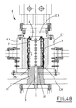
- the closed outer head (22) is aimed at adhering to the outer end of the tubular body (12) and at being fitted by the bottom (G) of the container (C), giving the latter a corresponding shape (see for example Figure 4A).
- the partially open inner head (21) of the covering (2) has a transversal first outer annular lip (23) and a second inner annular lip (24), which involve and adhere, respectively to the lower surface (14) and to the upper surface (15) of the annular groove (13) of the tubular core, defining, between the two lips, a tight proof chamber (25), whose function will be better explained and shown later on (see for example Figure 4A).
- the above mentioned base (11) of the tubular core (1) has at least one main conduit (3) extending from the relative lower face and opening into the tubular body (12).
- the main conduit (3) sets the inside of the tubular body (12) of the tubular core (1) in communication with the outside when the support element (S) is conveyed and then positioned at the forming station (A) and closing station (B), while it is connected to a delivery conduit of the pressurized fluid supply system (V), when the support element (S) is moved to the shaping station (D) inside the mold (E).
- the main conduit (3) has an additional branch conduit (31), which opens into a hole (16) made in the annular groove (13) of the tubular core (1) and which communicates with the tight proof chamber (25) defined by the outer annular lip (23) and inner annular lip (24).
- the presence of the additional branch conduit (31) allows, together with the introduction of the pressurized fluid into the tubular core (1) by the supply system (V), through the main conduit (3), to deform the tight proof chamber (25), so as to dilate its outer lateral walls, pushing them toward the inner walls of the mold (E).
- the mold (E) includes two semi-shells (E1) and (E2), which can be tightened together to enclose the lateral walls of the container (C), whose inner walls (F) are shaped according to the desired profile to be given to the lateral walls of the container (C).
- the mold (E) includes also an upper closing element (E3), which can be lowered until it goes in abutment against the bottom (G) of the container (C) and the closed outer head (22) of the covering (2) of the support element (S).
- the mold (E) includes heating means and cooling means, not shown, since of known type and not included in the scope of the present invention.
- the covering (2) which protects the inner walls of the container (C) from the direct contact with the operational fluid, introduced under pressure into the support element (S) in the shaping station (D), allows to use an operational fluid in liquid state, contrary to the prior art apparatuses.
- the proposed apparatus (100) has a hydraulic supply system (V), situated in the shaping station (D), below the conveying line (L), and introducing, after being joined to the main conduit (3) inside the base (11) of the tubular core (1), a pressurized fluid in a liquid state, into the support element (S).
- V hydraulic supply system
- the hydraulic supply system can introduce into the support element (S) the fluid in the liquid state, which cannot be compressed, with the pressure values considerably higher than the ones reached by the prior art apparatuses, in considerably shorter times, and without any blast risk.
- the hydraulic supply system can have valve means for regulating the flow of the liquid fluid, situated along the system delivery conduit to be joined to the main conduit (3).
- the main conduit (3) can have valve means (not shown), which can be opened or closed to optimize the introduction of the liquid fluid into the support element (S), and/or to adjust the flow of the liquid fluid from the support element (S).
- the proposed apparatus can form and shape a container also from materials like aluminium or tin, to obtain a can or other, similar containers.
- a liquid fluid allows to simplify the structure of the base of a support element, which has only one main conduit (3), used for the introduction of the pressurized liquid fluid into the support element (S), as well as for simultaneous activating, by the branch conduit (31), the deformation of the tight proof chamber (25), in order to assure the air-tightness.
- the presence of the covering (2) allows advantageously, as it has already been pointed out previously, to avoid the direct contact between the operational fluid and the inner walls of the container, thus protecting the latter from the contaminations, which can be produced by the impurities present in the fluid.
- the proposed apparatus (100) can also include a sterilizing station (Z) (shown with broken line in Figure 1), which is situated between the shaping station (D) and the forming station (A) and through which the support elements (S) pass, moved by the conveying line (L), after having been freed from the relative shaped container.
- a sterilizing station (Z) shown with broken line in Figure 1
- the covering (2) of the support element (S) is subjected to a sterilizing action before being conveyed to the forming station (A) and being fitted again onto a relative tubular element (T).
Landscapes
- Engineering & Computer Science (AREA)
- Manufacturing & Machinery (AREA)
- Mechanical Engineering (AREA)
- Blow-Moulding Or Thermoforming Of Plastics Or The Like (AREA)
- Making Paper Articles (AREA)
- Chemical Vapour Deposition (AREA)
- Containers And Plastic Fillers For Packaging (AREA)
- Auxiliary Devices For And Details Of Packaging Control (AREA)
Applications Claiming Priority (2)
| Application Number | Priority Date | Filing Date | Title |
|---|---|---|---|
| ITBO20040235 | 2004-04-21 | ||
| IT000235A ITBO20040235A1 (it) | 2004-04-21 | 2004-04-21 | Apparecchiatura per la formazione di un contenitore e la sagomatura del relativo profilo, a partire da un materiale in film |
Publications (3)
| Publication Number | Publication Date |
|---|---|
| EP1588835A2 true EP1588835A2 (fr) | 2005-10-26 |
| EP1588835A3 EP1588835A3 (fr) | 2007-07-11 |
| EP1588835B1 EP1588835B1 (fr) | 2009-12-23 |
Family
ID=34935459
Family Applications (1)
| Application Number | Title | Priority Date | Filing Date |
|---|---|---|---|
| EP05008641A Expired - Lifetime EP1588835B1 (fr) | 2004-04-21 | 2005-04-20 | Dispositif pour la fabrication et la formation d'un récipient à partir d'un film |
Country Status (4)
| Country | Link |
|---|---|
| EP (1) | EP1588835B1 (fr) |
| AT (1) | ATE452750T1 (fr) |
| DE (1) | DE602005018409D1 (fr) |
| IT (1) | ITBO20040235A1 (fr) |
Cited By (2)
| Publication number | Priority date | Publication date | Assignee | Title |
|---|---|---|---|---|
| EP1974898A3 (fr) * | 2007-03-29 | 2014-03-19 | Giorgio Trani | Procédé de formation de récipients tridimensionnels en matériau papier extensible |
| CN110997277A (zh) * | 2017-07-21 | 2020-04-10 | 斯蒂利亚诺斯·埃莱夫特里乌 | 用于通过吹塑来制造塑料制品的机器 |
Family Cites Families (5)
| Publication number | Priority date | Publication date | Assignee | Title |
|---|---|---|---|---|
| FR1223759A (fr) * | 1959-05-05 | 1960-06-20 | Tube souple et appareillage pour l'obtention de ce tube | |
| US4009982A (en) * | 1974-02-11 | 1977-03-01 | Universal Plastic Pipe Bending Corporation | Mechanism for forming an enlarged coupling on the ends of plastic pipe |
| DE2614576A1 (de) * | 1976-04-05 | 1977-10-13 | Farrell Plastic Mach | Blasformvorrichtung |
| DE10259641B4 (de) * | 2002-12-18 | 2006-03-23 | Carcoustics Tech Center Gmbh | Verwendung eines Formwerkzeuges zum Umformen von Halbzeugen aus Kunststoff |
| FR2854592A1 (fr) * | 2003-05-07 | 2004-11-12 | Newtec Internat Group | Systeme et procede de soufflage de corps creux en matiere plastique minimisant la consommation d'air haute pression |
-
2004
- 2004-04-21 IT IT000235A patent/ITBO20040235A1/it unknown
-
2005
- 2005-04-20 DE DE602005018409T patent/DE602005018409D1/de not_active Expired - Fee Related
- 2005-04-20 EP EP05008641A patent/EP1588835B1/fr not_active Expired - Lifetime
- 2005-04-20 AT AT05008641T patent/ATE452750T1/de not_active IP Right Cessation
Cited By (3)
| Publication number | Priority date | Publication date | Assignee | Title |
|---|---|---|---|---|
| EP1974898A3 (fr) * | 2007-03-29 | 2014-03-19 | Giorgio Trani | Procédé de formation de récipients tridimensionnels en matériau papier extensible |
| CN110997277A (zh) * | 2017-07-21 | 2020-04-10 | 斯蒂利亚诺斯·埃莱夫特里乌 | 用于通过吹塑来制造塑料制品的机器 |
| US11426918B2 (en) | 2017-07-21 | 2022-08-30 | Stylianos ELEFTHERIOU | Machine for manufacturing plastic items by blow moulding |
Also Published As
| Publication number | Publication date |
|---|---|
| ATE452750T1 (de) | 2010-01-15 |
| EP1588835A3 (fr) | 2007-07-11 |
| EP1588835B1 (fr) | 2009-12-23 |
| DE602005018409D1 (de) | 2010-02-04 |
| ITBO20040235A1 (it) | 2004-07-21 |
Similar Documents
| Publication | Publication Date | Title |
|---|---|---|
| KR101980130B1 (ko) | 포피식품의 성형방법 및 장치 | |
| ITMO20080085A1 (it) | Apparato per formare contenitori asettici | |
| EP2419668B1 (fr) | Appareil de transfert de matériau incohérent ou liquide | |
| US7827770B2 (en) | Method for the operation of a package emptying station | |
| NZ562266A (en) | Sealing bar | |
| US9289939B2 (en) | Apparatus and method of shaping plastics material pre-forms with separate flow paths for blowing air and control air | |
| US20100287893A1 (en) | Packaging machine and method for closing containers with lids | |
| JPH0398803A (ja) | 容器を充填する為の装置 | |
| EP1588835A2 (fr) | Dispositif pour la fabrication et la formation d'un récipient à partir d'un film | |
| CN114272131B (zh) | 传感器系统、生产设备以及用于转移传感器的方法 | |
| CN102672941A (zh) | 具有非灭菌媒介供应的灭菌吹塑机 | |
| MXPA04012837A (es) | Maquina empaquetadora y conformador. | |
| CN104724326B (zh) | 在一侧袋面具有容纳被包装物的凹部的袋制造方法和装置 | |
| US3175591A (en) | Sanitary dispensing nozzles for filling machines | |
| US8020590B2 (en) | Nozzle for filling a container with at least two viscous materials | |
| JPH05270525A (ja) | ヒートシールステーション | |
| US4574720A (en) | Method and apparatus for filling valved bags | |
| CN109231112B (zh) | 用于向物品填充可倾倒的产品的填充单元和填充方法 | |
| EP1155808A2 (fr) | Appareil pour dépressuriser et sceller des récipients en matière plastique produits par soufflage | |
| JPH05245533A (ja) | 押出プレスアセンブリ | |
| US7204258B2 (en) | Method for cleaning and/or disinfecting the vacuum channels of a sealing station | |
| JPH04229225A (ja) | 熱可塑性ウェブから中空部品を成形する方法および成形装置 | |
| KR20190127815A (ko) | 이중 백을 제조하기 위한 방법 및 장치 | |
| US11530062B2 (en) | Gas flush injector | |
| CZ2004999A3 (cs) | Způsob zpracování chybně naplněných obalů s nápoji a zařízení k provádění způsobu |
Legal Events
| Date | Code | Title | Description |
|---|---|---|---|
| PUAI | Public reference made under article 153(3) epc to a published international application that has entered the european phase |
Free format text: ORIGINAL CODE: 0009012 |
|
| AK | Designated contracting states |
Kind code of ref document: A2 Designated state(s): AT BE BG CH CY CZ DE DK EE ES FI FR GB GR HU IE IS IT LI LT LU MC NL PL PT RO SE SI SK TR |
|
| AX | Request for extension of the european patent |
Extension state: AL BA HR LV MK YU |
|
| PUAL | Search report despatched |
Free format text: ORIGINAL CODE: 0009013 |
|
| AK | Designated contracting states |
Kind code of ref document: A3 Designated state(s): AT BE BG CH CY CZ DE DK EE ES FI FR GB GR HU IE IS IT LI LT LU MC NL PL PT RO SE SI SK TR |
|
| AX | Request for extension of the european patent |
Extension state: AL BA HR LV MK YU |
|
| RIC1 | Information provided on ipc code assigned before grant |
Ipc: B31B 37/00 20060101ALI20070606BHEP Ipc: B29C 51/28 20060101ALI20070606BHEP Ipc: B31B 43/00 20060101AFI20050818BHEP Ipc: B29C 49/44 20060101ALI20070606BHEP |
|
| 17P | Request for examination filed |
Effective date: 20080108 |
|
| 17Q | First examination report despatched |
Effective date: 20080204 |
|
| AKX | Designation fees paid |
Designated state(s): AT BE BG CH CY CZ DE DK EE ES FI FR GB GR HU IE IS IT LI LT LU MC NL PL PT RO SE SI SK TR |
|
| GRAP | Despatch of communication of intention to grant a patent |
Free format text: ORIGINAL CODE: EPIDOSNIGR1 |
|
| GRAS | Grant fee paid |
Free format text: ORIGINAL CODE: EPIDOSNIGR3 |
|
| GRAA | (expected) grant |
Free format text: ORIGINAL CODE: 0009210 |
|
| AK | Designated contracting states |
Kind code of ref document: B1 Designated state(s): AT BE BG CH CY CZ DE DK EE ES FI FR GB GR HU IE IS IT LI LT LU MC NL PL PT RO SE SI SK TR |
|
| REG | Reference to a national code |
Ref country code: GB Ref legal event code: FG4D |
|
| REG | Reference to a national code |
Ref country code: CH Ref legal event code: EP |
|
| REG | Reference to a national code |
Ref country code: IE Ref legal event code: FG4D |
|
| REF | Corresponds to: |
Ref document number: 602005018409 Country of ref document: DE Date of ref document: 20100204 Kind code of ref document: P |
|
| REG | Reference to a national code |
Ref country code: NL Ref legal event code: VDEP Effective date: 20091223 |
|
| PG25 | Lapsed in a contracting state [announced via postgrant information from national office to epo] |
Ref country code: SE Free format text: LAPSE BECAUSE OF FAILURE TO SUBMIT A TRANSLATION OF THE DESCRIPTION OR TO PAY THE FEE WITHIN THE PRESCRIBED TIME-LIMIT Effective date: 20091223 Ref country code: LT Free format text: LAPSE BECAUSE OF FAILURE TO SUBMIT A TRANSLATION OF THE DESCRIPTION OR TO PAY THE FEE WITHIN THE PRESCRIBED TIME-LIMIT Effective date: 20091223 Ref country code: FI Free format text: LAPSE BECAUSE OF FAILURE TO SUBMIT A TRANSLATION OF THE DESCRIPTION OR TO PAY THE FEE WITHIN THE PRESCRIBED TIME-LIMIT Effective date: 20091223 |
|
| LTIE | Lt: invalidation of european patent or patent extension |
Effective date: 20091223 |
|
| PG25 | Lapsed in a contracting state [announced via postgrant information from national office to epo] |
Ref country code: PL Free format text: LAPSE BECAUSE OF FAILURE TO SUBMIT A TRANSLATION OF THE DESCRIPTION OR TO PAY THE FEE WITHIN THE PRESCRIBED TIME-LIMIT Effective date: 20091223 Ref country code: SI Free format text: LAPSE BECAUSE OF FAILURE TO SUBMIT A TRANSLATION OF THE DESCRIPTION OR TO PAY THE FEE WITHIN THE PRESCRIBED TIME-LIMIT Effective date: 20091223 |
|
| PG25 | Lapsed in a contracting state [announced via postgrant information from national office to epo] |
Ref country code: AT Free format text: LAPSE BECAUSE OF FAILURE TO SUBMIT A TRANSLATION OF THE DESCRIPTION OR TO PAY THE FEE WITHIN THE PRESCRIBED TIME-LIMIT Effective date: 20091223 |
|
| PG25 | Lapsed in a contracting state [announced via postgrant information from national office to epo] |
Ref country code: RO Free format text: LAPSE BECAUSE OF FAILURE TO SUBMIT A TRANSLATION OF THE DESCRIPTION OR TO PAY THE FEE WITHIN THE PRESCRIBED TIME-LIMIT Effective date: 20091223 Ref country code: NL Free format text: LAPSE BECAUSE OF FAILURE TO SUBMIT A TRANSLATION OF THE DESCRIPTION OR TO PAY THE FEE WITHIN THE PRESCRIBED TIME-LIMIT Effective date: 20091223 Ref country code: ES Free format text: LAPSE BECAUSE OF FAILURE TO SUBMIT A TRANSLATION OF THE DESCRIPTION OR TO PAY THE FEE WITHIN THE PRESCRIBED TIME-LIMIT Effective date: 20100403 Ref country code: PT Free format text: LAPSE BECAUSE OF FAILURE TO SUBMIT A TRANSLATION OF THE DESCRIPTION OR TO PAY THE FEE WITHIN THE PRESCRIBED TIME-LIMIT Effective date: 20100423 Ref country code: IS Free format text: LAPSE BECAUSE OF FAILURE TO SUBMIT A TRANSLATION OF THE DESCRIPTION OR TO PAY THE FEE WITHIN THE PRESCRIBED TIME-LIMIT Effective date: 20100423 Ref country code: EE Free format text: LAPSE BECAUSE OF FAILURE TO SUBMIT A TRANSLATION OF THE DESCRIPTION OR TO PAY THE FEE WITHIN THE PRESCRIBED TIME-LIMIT Effective date: 20091223 Ref country code: BG Free format text: LAPSE BECAUSE OF FAILURE TO SUBMIT A TRANSLATION OF THE DESCRIPTION OR TO PAY THE FEE WITHIN THE PRESCRIBED TIME-LIMIT Effective date: 20100323 |
|
| PG25 | Lapsed in a contracting state [announced via postgrant information from national office to epo] |
Ref country code: SK Free format text: LAPSE BECAUSE OF FAILURE TO SUBMIT A TRANSLATION OF THE DESCRIPTION OR TO PAY THE FEE WITHIN THE PRESCRIBED TIME-LIMIT Effective date: 20091223 Ref country code: BE Free format text: LAPSE BECAUSE OF FAILURE TO SUBMIT A TRANSLATION OF THE DESCRIPTION OR TO PAY THE FEE WITHIN THE PRESCRIBED TIME-LIMIT Effective date: 20091223 Ref country code: CZ Free format text: LAPSE BECAUSE OF FAILURE TO SUBMIT A TRANSLATION OF THE DESCRIPTION OR TO PAY THE FEE WITHIN THE PRESCRIBED TIME-LIMIT Effective date: 20091223 |
|
| PG25 | Lapsed in a contracting state [announced via postgrant information from national office to epo] |
Ref country code: GR Free format text: LAPSE BECAUSE OF FAILURE TO SUBMIT A TRANSLATION OF THE DESCRIPTION OR TO PAY THE FEE WITHIN THE PRESCRIBED TIME-LIMIT Effective date: 20100324 Ref country code: CY Free format text: LAPSE BECAUSE OF FAILURE TO SUBMIT A TRANSLATION OF THE DESCRIPTION OR TO PAY THE FEE WITHIN THE PRESCRIBED TIME-LIMIT Effective date: 20091223 |
|
| PLBE | No opposition filed within time limit |
Free format text: ORIGINAL CODE: 0009261 |
|
| STAA | Information on the status of an ep patent application or granted ep patent |
Free format text: STATUS: NO OPPOSITION FILED WITHIN TIME LIMIT |
|
| PG25 | Lapsed in a contracting state [announced via postgrant information from national office to epo] |
Ref country code: MC Free format text: LAPSE BECAUSE OF NON-PAYMENT OF DUE FEES Effective date: 20100430 |
|
| REG | Reference to a national code |
Ref country code: CH Ref legal event code: PL |
|
| 26N | No opposition filed |
Effective date: 20100924 |
|
| PG25 | Lapsed in a contracting state [announced via postgrant information from national office to epo] |
Ref country code: DK Free format text: LAPSE BECAUSE OF FAILURE TO SUBMIT A TRANSLATION OF THE DESCRIPTION OR TO PAY THE FEE WITHIN THE PRESCRIBED TIME-LIMIT Effective date: 20091223 Ref country code: IE Free format text: LAPSE BECAUSE OF NON-PAYMENT OF DUE FEES Effective date: 20100420 |
|
| PG25 | Lapsed in a contracting state [announced via postgrant information from national office to epo] |
Ref country code: CH Free format text: LAPSE BECAUSE OF NON-PAYMENT OF DUE FEES Effective date: 20100430 Ref country code: DE Free format text: LAPSE BECAUSE OF NON-PAYMENT OF DUE FEES Effective date: 20101103 Ref country code: LI Free format text: LAPSE BECAUSE OF NON-PAYMENT OF DUE FEES Effective date: 20100430 |
|
| PG25 | Lapsed in a contracting state [announced via postgrant information from national office to epo] |
Ref country code: HU Free format text: LAPSE BECAUSE OF FAILURE TO SUBMIT A TRANSLATION OF THE DESCRIPTION OR TO PAY THE FEE WITHIN THE PRESCRIBED TIME-LIMIT Effective date: 20100624 Ref country code: LU Free format text: LAPSE BECAUSE OF NON-PAYMENT OF DUE FEES Effective date: 20100420 |
|
| PG25 | Lapsed in a contracting state [announced via postgrant information from national office to epo] |
Ref country code: TR Free format text: LAPSE BECAUSE OF FAILURE TO SUBMIT A TRANSLATION OF THE DESCRIPTION OR TO PAY THE FEE WITHIN THE PRESCRIBED TIME-LIMIT Effective date: 20091223 |
|
| PGFP | Annual fee paid to national office [announced via postgrant information from national office to epo] |
Ref country code: GB Payment date: 20140424 Year of fee payment: 10 |
|
| PGFP | Annual fee paid to national office [announced via postgrant information from national office to epo] |
Ref country code: FR Payment date: 20140424 Year of fee payment: 10 Ref country code: IT Payment date: 20140429 Year of fee payment: 10 |
|
| GBPC | Gb: european patent ceased through non-payment of renewal fee |
Effective date: 20150420 |
|
| PG25 | Lapsed in a contracting state [announced via postgrant information from national office to epo] |
Ref country code: GB Free format text: LAPSE BECAUSE OF NON-PAYMENT OF DUE FEES Effective date: 20150420 Ref country code: IT Free format text: LAPSE BECAUSE OF NON-PAYMENT OF DUE FEES Effective date: 20150420 |
|
| REG | Reference to a national code |
Ref country code: FR Ref legal event code: ST Effective date: 20151231 |
|
| PG25 | Lapsed in a contracting state [announced via postgrant information from national office to epo] |
Ref country code: FR Free format text: LAPSE BECAUSE OF NON-PAYMENT OF DUE FEES Effective date: 20150430 |