EP1589152B1 - Système de protection contre les crues - Google Patents
Système de protection contre les crues Download PDFInfo
- Publication number
- EP1589152B1 EP1589152B1 EP05405312A EP05405312A EP1589152B1 EP 1589152 B1 EP1589152 B1 EP 1589152B1 EP 05405312 A EP05405312 A EP 05405312A EP 05405312 A EP05405312 A EP 05405312A EP 1589152 B1 EP1589152 B1 EP 1589152B1
- Authority
- EP
- European Patent Office
- Prior art keywords
- protective
- plate
- base plate
- protection system
- plates
- Prior art date
- Legal status (The legal status is an assumption and is not a legal conclusion. Google has not performed a legal analysis and makes no representation as to the accuracy of the status listed.)
- Expired - Lifetime
Links
- 230000004224 protection Effects 0.000 title claims abstract description 55
- XLYOFNOQVPJJNP-UHFFFAOYSA-N water Substances O XLYOFNOQVPJJNP-UHFFFAOYSA-N 0.000 title claims description 24
- 230000001681 protective effect Effects 0.000 claims abstract description 79
- 239000004567 concrete Substances 0.000 claims abstract description 13
- 230000003014 reinforcing effect Effects 0.000 claims abstract description 10
- 238000007789 sealing Methods 0.000 claims description 26
- 239000011150 reinforced concrete Substances 0.000 claims description 6
- 238000000034 method Methods 0.000 claims description 4
- 239000000463 material Substances 0.000 claims description 3
- 239000002131 composite material Substances 0.000 claims description 2
- 239000011440 grout Substances 0.000 claims 6
- 230000002787 reinforcement Effects 0.000 claims 4
- 230000000694 effects Effects 0.000 claims 3
- 230000008602 contraction Effects 0.000 claims 2
- 230000001154 acute effect Effects 0.000 description 5
- 238000004873 anchoring Methods 0.000 description 4
- 239000002184 metal Substances 0.000 description 4
- 229910052751 metal Inorganic materials 0.000 description 4
- 238000006424 Flood reaction Methods 0.000 description 3
- 230000008859 change Effects 0.000 description 3
- 238000010276 construction Methods 0.000 description 3
- 238000007667 floating Methods 0.000 description 3
- 238000009434 installation Methods 0.000 description 3
- XEEYBQQBJWHFJM-UHFFFAOYSA-N Iron Chemical compound [Fe] XEEYBQQBJWHFJM-UHFFFAOYSA-N 0.000 description 2
- 230000008014 freezing Effects 0.000 description 2
- 238000007710 freezing Methods 0.000 description 2
- 230000002829 reductive effect Effects 0.000 description 2
- 239000003643 water by type Substances 0.000 description 2
- 229910000669 Chrome steel Inorganic materials 0.000 description 1
- 229910000746 Structural steel Inorganic materials 0.000 description 1
- 238000009825 accumulation Methods 0.000 description 1
- 239000000654 additive Substances 0.000 description 1
- 230000000996 additive effect Effects 0.000 description 1
- 230000004888 barrier function Effects 0.000 description 1
- 230000001010 compromised effect Effects 0.000 description 1
- 230000001419 dependent effect Effects 0.000 description 1
- 239000003673 groundwater Substances 0.000 description 1
- 230000003993 interaction Effects 0.000 description 1
- 229910052742 iron Inorganic materials 0.000 description 1
- 230000000149 penetrating effect Effects 0.000 description 1
- 230000009979 protective mechanism Effects 0.000 description 1
- 230000000284 resting effect Effects 0.000 description 1
- 230000003068 static effect Effects 0.000 description 1
- 230000008961 swelling Effects 0.000 description 1
- 230000009182 swimming Effects 0.000 description 1
Images


Classifications
-
- E—FIXED CONSTRUCTIONS
- E02—HYDRAULIC ENGINEERING; FOUNDATIONS; SOIL SHIFTING
- E02B—HYDRAULIC ENGINEERING
- E02B3/00—Engineering works in connection with control or use of streams, rivers, coasts, or other marine sites; Sealings or joints for engineering works in general
- E02B3/04—Structures or apparatus for, or methods of, protecting banks, coasts, or harbours
- E02B3/10—Dams; Dykes; Sluice ways or other structures for dykes, dams, or the like
- E02B3/102—Permanently installed raisable dykes
Definitions
- the invention relates to a flood protection system typically with a plurality of protective elements, in which flood protection is erected by folding protective elements.
- flood protection is a well-known problem especially in densely populated areas, which are threatened by rivers, lakes or also by their proximity to the sea. But also for the protection of important civilian or even military installations and facilities a functioning flood protection is an increasingly important task. While in areas with frequent or permanent hazard potential, especially in coastal areas with storm surge danger, usually dikes with a maximum hazard potential corresponding protection height are used, was long time in areas with only occasional flood hazard potential on emergency measures, e.g. with the protection of areas with sandbags or exceptionally with dam beams, resorted to in acute danger.
- dams and dikes of appropriate height or completely off.
- the boundaries between the water from which the hazard originates and the vulnerable zones in many cases run straight in populated areas, so that obstructing such dams and dykes does not meet with the acceptance required for safety.
- the structural measures do not or only slightly disturbing, if the threat is not acute, so at normal or only slightly increased water level.
- a structural measure with hinged elements in which a receiving chamber on the one hand, a floodable swimming chamber and on the other hand, a Einschwenkhunt includes and the pivoting element is pivoted from the horizontal to the vertical.
- the structural measure described there is based on the basic idea of causing or at least supporting the swiveling out by the floating of the protective wall designed as a pontoon part in the floating chamber. However, this has not turned out to be advantageous.
- the surface of the protective elements should be used for other purposes at those times when there is no acute danger, such as footpaths, driveways, etc.
- a flood protection is known in which the floating chamber can already be dispensed with and in which by means of a drive means the protective position in the unfolded state or the rest position can be taken. In the unfolded state while a part of the flap wall is lowered into a channel substructure.
- the drive device be effective in or on the pivot bearing.
- German utility model DE-202 04 097 U1 is one of the WO 99/24675 A1 advanced flood protection with hinged elements known, which also has a channel for lowering a portion of the folding elements and for receiving the drive elements.
- the invention solves the problem by a flood protection according to claim 1 and a method according to claim 16.
- the measures of the invention initially have the consequence that the base plates are sealed against each other and that a relatively simple and inexpensive construction can be implemented standardized, without that the protection requirements against the flood threat would have to be compromised.
- Another consequence of the measures of the invention is that it is possible to dispense with a separate, at most, vulnerable drive system for erecting the protective elements, without necessitating a high level of manual effort.
- Contribute to the measures of the invention in their combination Due to the special nature of the interaction of the elements is taken into account in particular that a freezing of the elements by penetrating rainwater etc. prevents safe opening. With a corresponding design of the thickness of the elements safe driving is also possible without damaging the elements in the folded state, since - in contrast to the in the DE-A-102 40 687 proposed solution - a touching flap surface can be ensured.
- the flood protection system comprises a plurality of protective elements, each at least a first, pivotable protective plate for forming a protective wall in a tilted state in an inclined position and to form a substantially flat surface in a horizontal, Schutz Signswin state, a second, approximately horizontally on the ground fixed base plate, at least two support means - preferably heavy duty ceiling supports with top plates -
- sealing means for sealing the protective plate against the base plate and for sealing two juxtaposed protective plates against each other, namely sealing tapes that can be used without friction surface. The sealing means then act sealing when the protective plates are in the swung-open protective state.
- the base plates are chamfered down to the side of the adjacent base plate, respectively, because they can be reliably relocated with minimum clearance through the use of tools (e.g., lift trucks).
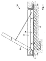
- the designated in Figure 1 as a whole with 100 flood protection system consists of a bottom element as applied to an L-shaped reinforced concrete foundation 60 base plate 30 and to the base plate 30 made of reinforced concrete with a hinge 40 pivotally mounted protective plate 20 - also made of reinforced concrete.
- a final foundation 210 is to see, usually a road or building completion.
- the end foundation 220 forms a channel towards the side of the plate to allow a smooth pivoting of the protective plate 20.
- each base plate 30 has four anchoring holes - to see, with which the base plate 30 on - in the present embodiment, L-shaped - reinforced concrete foundation 60 is fixed by means of composite anchors.
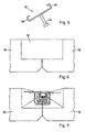
- FIG. 2 shows the protective plates 20 used in the present exemplary embodiment.
- FIG 3 the side by side arranged base plates 30 are shown, which are sealed with each other with a Vergussbetonmasse 72.
- the grouting concrete mass 72 has an E-modulus which is selected such that the concreting takes place without shrinkage cracks occurring.
- the Vergussbetonmasse is thereby filled in an area which are formed by recesses respectively at the edges of the base plates 30 and in which are Renarmtechniksbügel, which overlap each other after the finished assembly of the elements.
- so-called distribution iron are used before the concreting is carried out with the special grouting concrete with sealing additive.
- Figure 4 shows the hinge means 40 for the pivotal movement of the protective plate 20 against the base plate 30. It has been found that for a plate with a length of 6 m (relative to the bottom plate 30) two chrome steel hinges with a length of 150 mm and a thickness of 20 mm suffice.
- - particularly advantageous - anchoring plates 42 and 43 with a thickness of 20 mm and a depth of typically 70 to 120 mm - in the embodiment of 90 mm - in the protective plate 20 and in the base plate 30 at an angle of about 45 ° incorporated.
- the two plates 20 and 30 are chamfered at an angle of approximately 30 ° and a depth of approximately 370 mm in order to allow an opening region for the opening of the hinge and thus the swiveling up of the protective plate 20 ,
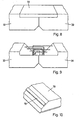
- this chamfered region in the described embodiment, approximately in the middle, sealing strips 70 are arranged both on the base plate 30 and on the protective plate 20 over the entire length of the plates. This relationship is also apparent from Fig. 10.
- FIG. 5 shows the configuration of the support supports 52.
- the support supports 52 have laterally a holder 58 into which the top plates 56 of the heavy-duty ceiling supports 50 are inserted.
- heavy-duty ceiling supports according to DIN 4424 are provided in order to use a standard part if necessary.
- the support supports 52 are anchored in the protective plates 20 as well as in the bottom plates 30 by means of the head bolt dowels 54 and have in the present embodiment at an angle of 30 ° to 45 ° relative to the plate surface so that they can support the top plates 56 of the heavy duty ceiling supports 50 just.
- recesses for receiving the heavy duty ceiling supports 50 are provided in the resting state of the flood protection system in the bottom plates.
- the particularly advantageous protective mechanism of the flood protection system according to the invention results, in which a pivoting of the protective plate 20 is provided by about 60 °. If this angle is to be changed, it must - in addition to the length described below. Supports 50 and the mounting arrangement - to the angle of the chamfering of the two plates 20 and 30 are changed. However, it has been found that a pivoting of the protective plates 20 by 55 ° to 65 °, preferably in about 60 ° allows the best static conditions.
- the erecting of the protective plates 20 is provided according to the present invention by means of a lifting device (jib crane), which raises the individual protective plates 20 of the flood protection system successively and thus produces a protective barrier.
- a lifting device jib crane
- the protective plates 20 with the widening formed above each be raised first.
- a manual erection of the protective plates 20 is possible for the flood protection system described here, but this requires the use of some people.
- two of the heavy-load ceiling supports 50 described above per protective plate 20 are then inserted into the holder for the top plates and can at best even by a securing element (fasteners such as bolts, cotter pin or the like) are secured.
- the high-wave protective elements can be connected laterally to existing buildings, etc.
- the buildings are provided, for example, with facilities that correspond to the joint seals between the individual protective plates 20 and are equally effective. This can be effected by oblique projections as in the protective plates 20.
- the obliquely erected protective plates can be temporarily sealed to the corresponding structures after erection, e.g. by metal angles, etc.
- threaded elements are then provided in the outer protective plates 20 in order to sealably secure such angles to the protective plates.
Landscapes
- Engineering & Computer Science (AREA)
- General Engineering & Computer Science (AREA)
- Environmental & Geological Engineering (AREA)
- Ocean & Marine Engineering (AREA)
- Mechanical Engineering (AREA)
- Civil Engineering (AREA)
- Structural Engineering (AREA)
- Buildings Adapted To Withstand Abnormal External Influences (AREA)
- Air Bags (AREA)
- Revetment (AREA)
Claims (18)
- Système de protection contre les crues comportant une pluralité d'éléments de protection, les éléments de protection comprenant au moins- une première plaque de protection (20) pivotante destinée à former une paroi de protection lorsqu'elle a été pivotée dans une position inclinée et à former une surface essentiellement plane lorsqu'elle est horizontale et n'exerce pas d'action de protection,- une deuxième plaque de base (30) installée de façon fixe au sol à peu près horizontalement, la plaque de protection (20) et la plaque de base (30) étant reliées de façon à pouvoir pivoter avec un moyen de palier rotatif ou pivotant (40) et la plaque de base (30) présentant des moyens d'ancrage dans le sol,- des moyens de support (50) destinés à supporter la plaque de protection (20) lorsqu'elle a été pivotée dans la position inclinée,- un premier moyen d'étanchéité (70) destiné à assurer l'étanchéité de la plaque de protection (20) par rapport à la plaque de base (30), le moyen d'étanchéité assurant au moins l'étanchéité lorsque la plaque de protection (20) se trouve en position de protection après avoir été pivotée vers le haut,caractérisé en ce que- la plaque de base (30) présente des moyens par lesquels elle peut être respectivement reliée à une plaque de base disposée de manière contiguë,- les moyens comprenant au moins un évidement au bord de la plaque de base et des éléments d'armature pénétrant dans l'évidement,- l'évidement étant dimensionné de telle manière que deux plaques de base situées l'une à côté de l'autre peuvent être reliées entre elles par du béton coulé.
- Système de protection contre les crues selon la revendication 1, caractérisé en ce que les éléments d'armature sont prévus sous la forme d'étriers d'armature de raccordement et les plaques de base sont reliées entre elles par du béton coulé de telle manière que les étriers d'armature et les évidements sont coulés.
- Système de protection contre les crues selon la revendication 2, caractérisé en ce que comme béton coulé on choisit un matériau dont le module d'élasticité permet de réaliser le bétonnage sans l'apparition de fissures de retrait.
- Système de protection contre les crues selon l'une des revendications précédentes, caractérisé en ce que la plaque de base est chanfreinée en bas du côté de la plaque de base contiguë.
- Système de protection contre les crues selon l'une des revendications précédentes, caractérisé en ce que la plaque de base et la plaque de protection, chacune dans la zone de leur ligne de liaison, sont chanfreinées et que l'angle formé conjointement correspond à peu près à l'angle de pivotement prévu.
- Système de protection contre les crues selon l'une des revendications précédentes, caractérisé par un deuxième moyen d'étanchéité (70) destiné à assurer l'étanchéité l'une par rapport à l'autre de deux plaques de protection (20) disposées l'une à côté de l'autre, le deuxième moyen d'étanchéité assurant l'étanchéité lorsque les plaques de protection (20) se trouvent en position de protection après avoir été pivotées vers le haut.
- Système de protection contre les crues selon l'une des revendications précédentes, caractérisé en ce que les moyens d'étanchéité comprennent des bandes d'étanchéité (70).
- Système de protection contre les crues selon l'une des revendications précédentes, caractérisé en ce que les plaques de protection (20) présentent des joints (24) chevauchant.
- Système de protection contre les crues selon la revendication 8, caractérisé en ce que le deuxième moyen d'étanchéité réalisé sous la forme de bandes d'étanchéité (70) est réalisé dans un joint (24) chevauchant entre deux plaques de protection respectives (20).
- Système de protection contre les crues selon la revendication 8 ou 9, caractérisé par des plaques de protection (20) de types différents, un type de plaque de protection (20) présentant des deux côtés un élargissement (26) dépassant en bas dans la position allongée et l'autre type de plaque de protection (20) présentant des deux côtés un élargissement (28) dépassant en haut dans la position allongée et les élargissements (26, 28) occupant environ la moitié de l'épaisseur des plaques de protection (20).
- Système de protection contre les crues selon l'une des revendications précédentes, caractérisé en ce que les moyens de support (50) sont réalisés chacun sous la forme de support de plafond supportant des charges lourdes avec des plaques de tête (56).
- Système de protection contre les crues selon la revendication 11, caractérisé en ce que la plaque de protection (20) et la plaque de base (30) présentent chacune des appuis de support (52) avec des boulons à tête (54) et une fixation (58) pour les plaques de tête (56) des supports (50).
- Système de protection contre les crues selon l'une des revendications précédentes, caractérisé en ce que la plaque de base (30) présente une gouttière d'écoulement d'eau (32).
- Système de protection contre les crues selon l'une des revendications précédentes, caractérisé en ce que chaque plaque de base (30) est fixée avec des ancrages composites sur une fondation, la fondation étant réalisée de préférence sous la forme de fondation en béton armé (60) en forme de L.
- Système de protection contre les crues selon l'une des revendications précédentes, caractérisé par une pluralité de dispositifs d'ajustement sur les plaques de base (30) destinés à ajuster les plaques sur la fondation (60).
- Procédé pour déplacer des éléments de protection d'un système de protection contre les crues, les éléments de protection comprenant au moins- une première plaque de protection (20) pivotante destinée à former une paroi de protection lorsqu'elle a été pivotée dans une position inclinée et à former une surface essentiellement plane lorsqu'elle est horizontale et n'exerce pas d'action de protection,- une deuxième plaque de base (30) installée de façon fixe au sol à peu près horizontalement, la plaque de protection (20) et la plaque de fond (30) étant reliées de façon à pouvoir pivoter avec un moyen de palier rotatif ou pivotant (40) et la plaque de base (30) présentant des moyens d'ancrage dans le sol,- des moyens de support (50) destinés à supporter la plaque de protection (20) lorsqu'elle a été pivotée dans la position inclinée,- un premier moyen d'étanchéité (70) destiné à assurer l'étanchéité de la plaque de protection (20) par rapport à la plaque de base (30), le moyen d'étanchéité assurant au moins l'étanchéité lorsque la plaque de protection (20) se trouve en position de protection après avoir été pivotée vers le haut,caractérisé en ce que- chaque plaque de base (30) est reliée à une plaque de base disposée de manière contiguë,- un évidement au bord de la plaque de base étant relié par du béton coulé à des éléments d' armature pénétrant dans l'évidement.
- Procédé selon la revendication 16, caractérisé en ce que, comme éléments d'armature, on utilise des étriers d'armature de raccordement et les plaques de base sont reliées entre elles par du béton coulé, les étriers d'armature et les évidements étant coulés.
- Procédé selon la revendication 17, caractérisé en ce que, comme béton coulé, on utilise un matériau dont le module d'élasticité permet la réalisation du bétonnage sans l'apparition de fissures de retrait.
Applications Claiming Priority (2)
| Application Number | Priority Date | Filing Date | Title |
|---|---|---|---|
| CH6972004 | 2004-04-22 | ||
| CH6972004 | 2004-04-22 |
Publications (3)
| Publication Number | Publication Date |
|---|---|
| EP1589152A2 EP1589152A2 (fr) | 2005-10-26 |
| EP1589152A3 EP1589152A3 (fr) | 2007-03-07 |
| EP1589152B1 true EP1589152B1 (fr) | 2007-12-12 |
Family
ID=34942974
Family Applications (1)
| Application Number | Title | Priority Date | Filing Date |
|---|---|---|---|
| EP05405312A Expired - Lifetime EP1589152B1 (fr) | 2004-04-22 | 2005-04-22 | Système de protection contre les crues |
Country Status (3)
| Country | Link |
|---|---|
| EP (1) | EP1589152B1 (fr) |
| AT (1) | ATE380904T1 (fr) |
| DE (1) | DE502005002185D1 (fr) |
Families Citing this family (5)
| Publication number | Priority date | Publication date | Assignee | Title |
|---|---|---|---|---|
| CN107338761B (zh) * | 2016-11-24 | 2019-04-26 | 国家电网公司 | 隐藏式防汛系统 |
| DE102017130818B3 (de) * | 2017-12-20 | 2018-11-15 | Tu Kaiserslautern | Wassersperre mit einem rinnenförmigen Gründungkörper |
| GB2598447B (en) | 2020-11-20 | 2022-11-02 | Flood Control International Ltd | Improvements relating to flood defence |
| CN115419020B (zh) * | 2022-10-11 | 2023-08-04 | 矿冶科技集团有限公司 | 应急封堵装置、排洪系统及封堵方法 |
| CN116497763A (zh) * | 2023-05-04 | 2023-07-28 | 河南灵捷水利勘测设计研究有限公司 | 一种水利防洪堤坝 |
Family Cites Families (6)
| Publication number | Priority date | Publication date | Assignee | Title |
|---|---|---|---|---|
| DE48642C (de) * | A. HARTMANN SOHN in Frankfurt a. M., Neue Kräme 18 | Umlegbare eiserne Schutzwand gegen Hochwasser für Uferstrafsen | ||
| FR2295174A1 (fr) * | 1974-12-20 | 1976-07-16 | Nomballais Jean | Dispositif de commande d'ouverture semi-automatique de porte de barrage a commande manuelle |
| DE7831215U1 (de) * | 1978-10-20 | 1979-03-15 | 8411 Lappersdorf | Transportabler hochwasser-schild zur erhoehung von hochwasserschutzmauern, deichen und sonstigen uferbefestigungsanlagen an gewaessern |
| DE19531922C2 (de) * | 1995-08-30 | 1999-06-17 | Erich Joseph Dipl Ing Bott | Spundwand zum Schutz gegen Hochwasser |
| DE10240687A1 (de) * | 2002-09-04 | 2004-04-15 | Juri Riedel | Universelle Schutzanlage für den Einsatz bei Hochwasser |
| DE20313425U1 (de) * | 2003-08-29 | 2003-11-13 | WIHAG Nutzfahrzeugfabrik GmbH & Co. KG, 33647 Bielefeld | Rückhalteelemente |
-
2005
- 2005-04-22 AT AT05405312T patent/ATE380904T1/de active
- 2005-04-22 DE DE502005002185T patent/DE502005002185D1/de not_active Expired - Lifetime
- 2005-04-22 EP EP05405312A patent/EP1589152B1/fr not_active Expired - Lifetime
Also Published As
| Publication number | Publication date |
|---|---|
| ATE380904T1 (de) | 2007-12-15 |
| EP1589152A3 (fr) | 2007-03-07 |
| DE502005002185D1 (de) | 2008-01-24 |
| EP1589152A2 (fr) | 2005-10-26 |
Similar Documents
| Publication | Publication Date | Title |
|---|---|---|
| DE69926791T2 (de) | Staudamm und abdichtungsverfahren | |
| EP0741205B1 (fr) | Système de protection contre les crues avec un ou plusieurs éléments muraux abaissables | |
| DE29620193U1 (de) | Mobile Vorrichtung zum Schutz gegen Hochwasser | |
| DE2844748C2 (de) | Entwässerungsrinne | |
| EP2090698A1 (fr) | Blocage de l'eau, notamment paroi de protection contre les montées d'eaux | |
| CH707671A2 (de) | Stützmauerelement und Stützmauer aus Stützmauerelementen. | |
| EP1029130A1 (fr) | Elements de protection, dispositifs comprenant de tels elements et procede pour proteger une zone contre les crues ou les avalanches | |
| EP0802285A2 (fr) | Système de protection contre les crues | |
| EP2921599B1 (fr) | Élément de montage d'un canal et procédé de pose d'élément | |
| DE202008014492U1 (de) | Abdichtung von Kanälen | |
| DE19539611C2 (de) | Hochwasser-Rückhaltesperre | |
| WO2016110438A1 (fr) | Système de protection contre les crues | |
| EP1589152A2 (fr) | Système de protection contre les crues | |
| AT16289U1 (de) | Schott für den Hochwasserschutz und Durchgang mit einem solchen Schott | |
| DE102004033962B4 (de) | Versenkbare Flutwasserschutzanlage | |
| DE2321647A1 (de) | Verfahren und fertigteil zum herstellen einer kern- oder oberflaechendichtung | |
| DE102004015322B4 (de) | Hochwasserbarriere | |
| DE102004025456A1 (de) | Zerlegbare Stauwand | |
| DE20308083U1 (de) | Hochwasser-Schutzsystem | |
| DE20102852U1 (de) | Plattensystem | |
| LU506449B1 (en) | Ein zusammengebautes wiederverwendbares drainagesystem für den grubenausbau in regenreichen gebieten | |
| AT516886B1 (de) | Selbsterrichtende und selbstarritierende Hochwasserschutzvorrichtung | |
| EP1738050B1 (fr) | Mur de protection, en particulier mur de protection contre les crues | |
| DE1970492U (de) | Boeschungsmatte zur sicherung von erdbauwerken. | |
| DE202005003576U1 (de) | Systemwand |
Legal Events
| Date | Code | Title | Description |
|---|---|---|---|
| PUAI | Public reference made under article 153(3) epc to a published international application that has entered the european phase |
Free format text: ORIGINAL CODE: 0009012 |
|
| AK | Designated contracting states |
Kind code of ref document: A2 Designated state(s): AT BE BG CH CY CZ DE DK EE ES FI FR GB GR HU IE IS IT LI LT LU MC NL PL PT RO SE SI SK TR |
|
| AX | Request for extension of the european patent |
Extension state: AL BA HR LV MK YU |
|
| PUAL | Search report despatched |
Free format text: ORIGINAL CODE: 0009013 |
|
| AK | Designated contracting states |
Kind code of ref document: A3 Designated state(s): AT BE BG CH CY CZ DE DK EE ES FI FR GB GR HU IE IS IT LI LT LU MC NL PL PT RO SE SI SK TR |
|
| AX | Request for extension of the european patent |
Extension state: AL BA HR LV MK YU |
|
| 17P | Request for examination filed |
Effective date: 20070315 |
|
| GRAP | Despatch of communication of intention to grant a patent |
Free format text: ORIGINAL CODE: EPIDOSNIGR1 |
|
| GRAS | Grant fee paid |
Free format text: ORIGINAL CODE: EPIDOSNIGR3 |
|
| GRAA | (expected) grant |
Free format text: ORIGINAL CODE: 0009210 |
|
| AKX | Designation fees paid |
Designated state(s): AT BE BG CH CY CZ DE DK EE ES FI FR GB GR HU IE IS IT LI LT LU MC NL PL PT RO SE SI SK TR |
|
| AK | Designated contracting states |
Kind code of ref document: B1 Designated state(s): AT BE BG CH CY CZ DE DK EE ES FI FR GB GR HU IE IS IT LI LT LU MC NL PL PT RO SE SI SK TR |
|
| REG | Reference to a national code |
Ref country code: GB Ref legal event code: FG4D Free format text: NOT ENGLISH |
|
| REG | Reference to a national code |
Ref country code: CH Ref legal event code: EP |
|
| REG | Reference to a national code |
Ref country code: IE Ref legal event code: FG4D Free format text: LANGUAGE OF EP DOCUMENT: GERMAN |
|
| REF | Corresponds to: |
Ref document number: 502005002185 Country of ref document: DE Date of ref document: 20080124 Kind code of ref document: P |
|
| REG | Reference to a national code |
Ref country code: CH Ref legal event code: NV Representative=s name: R. A. EGLI & CO. PATENTANWAELTE |
|
| GBT | Gb: translation of ep patent filed (gb section 77(6)(a)/1977) |
Effective date: 20080312 |
|
| PG25 | Lapsed in a contracting state [announced via postgrant information from national office to epo] |
Ref country code: SE Free format text: LAPSE BECAUSE OF FAILURE TO SUBMIT A TRANSLATION OF THE DESCRIPTION OR TO PAY THE FEE WITHIN THE PRESCRIBED TIME-LIMIT Effective date: 20080312 |
|
| PG25 | Lapsed in a contracting state [announced via postgrant information from national office to epo] |
Ref country code: FI Free format text: LAPSE BECAUSE OF FAILURE TO SUBMIT A TRANSLATION OF THE DESCRIPTION OR TO PAY THE FEE WITHIN THE PRESCRIBED TIME-LIMIT Effective date: 20071212 Ref country code: LT Free format text: LAPSE BECAUSE OF FAILURE TO SUBMIT A TRANSLATION OF THE DESCRIPTION OR TO PAY THE FEE WITHIN THE PRESCRIBED TIME-LIMIT Effective date: 20071212 Ref country code: PL Free format text: LAPSE BECAUSE OF FAILURE TO SUBMIT A TRANSLATION OF THE DESCRIPTION OR TO PAY THE FEE WITHIN THE PRESCRIBED TIME-LIMIT Effective date: 20071212 Ref country code: SI Free format text: LAPSE BECAUSE OF FAILURE TO SUBMIT A TRANSLATION OF THE DESCRIPTION OR TO PAY THE FEE WITHIN THE PRESCRIBED TIME-LIMIT Effective date: 20071212 |
|
| REG | Reference to a national code |
Ref country code: FR Ref legal event code: RN |
|
| REG | Reference to a national code |
Ref country code: FR Ref legal event code: FC |
|
| PG25 | Lapsed in a contracting state [announced via postgrant information from national office to epo] |
Ref country code: IS Free format text: LAPSE BECAUSE OF FAILURE TO SUBMIT A TRANSLATION OF THE DESCRIPTION OR TO PAY THE FEE WITHIN THE PRESCRIBED TIME-LIMIT Effective date: 20080412 Ref country code: CZ Free format text: LAPSE BECAUSE OF FAILURE TO SUBMIT A TRANSLATION OF THE DESCRIPTION OR TO PAY THE FEE WITHIN THE PRESCRIBED TIME-LIMIT Effective date: 20071212 Ref country code: ES Free format text: LAPSE BECAUSE OF FAILURE TO SUBMIT A TRANSLATION OF THE DESCRIPTION OR TO PAY THE FEE WITHIN THE PRESCRIBED TIME-LIMIT Effective date: 20080323 |
|
| PG25 | Lapsed in a contracting state [announced via postgrant information from national office to epo] |
Ref country code: SK Free format text: LAPSE BECAUSE OF FAILURE TO SUBMIT A TRANSLATION OF THE DESCRIPTION OR TO PAY THE FEE WITHIN THE PRESCRIBED TIME-LIMIT Effective date: 20071212 Ref country code: RO Free format text: LAPSE BECAUSE OF FAILURE TO SUBMIT A TRANSLATION OF THE DESCRIPTION OR TO PAY THE FEE WITHIN THE PRESCRIBED TIME-LIMIT Effective date: 20071212 |
|
| EN | Fr: translation not filed | ||
| PG25 | Lapsed in a contracting state [announced via postgrant information from national office to epo] |
Ref country code: PT Free format text: LAPSE BECAUSE OF FAILURE TO SUBMIT A TRANSLATION OF THE DESCRIPTION OR TO PAY THE FEE WITHIN THE PRESCRIBED TIME-LIMIT Effective date: 20080512 |
|
| REG | Reference to a national code |
Ref country code: IE Ref legal event code: FD4D |
|
| ET | Fr: translation filed | ||
| PLBE | No opposition filed within time limit |
Free format text: ORIGINAL CODE: 0009261 |
|
| STAA | Information on the status of an ep patent application or granted ep patent |
Free format text: STATUS: NO OPPOSITION FILED WITHIN TIME LIMIT |
|
| PG25 | Lapsed in a contracting state [announced via postgrant information from national office to epo] |
Ref country code: FR Free format text: LAPSE BECAUSE OF FAILURE TO SUBMIT A TRANSLATION OF THE DESCRIPTION OR TO PAY THE FEE WITHIN THE PRESCRIBED TIME-LIMIT Effective date: 20080926 Ref country code: IE Free format text: LAPSE BECAUSE OF FAILURE TO SUBMIT A TRANSLATION OF THE DESCRIPTION OR TO PAY THE FEE WITHIN THE PRESCRIBED TIME-LIMIT Effective date: 20071212 Ref country code: DK Free format text: LAPSE BECAUSE OF FAILURE TO SUBMIT A TRANSLATION OF THE DESCRIPTION OR TO PAY THE FEE WITHIN THE PRESCRIBED TIME-LIMIT Effective date: 20071212 |
|
| 26N | No opposition filed |
Effective date: 20080915 |
|
| PG25 | Lapsed in a contracting state [announced via postgrant information from national office to epo] |
Ref country code: MC Free format text: LAPSE BECAUSE OF NON-PAYMENT OF DUE FEES Effective date: 20080430 |
|
| PG25 | Lapsed in a contracting state [announced via postgrant information from national office to epo] |
Ref country code: GR Free format text: LAPSE BECAUSE OF FAILURE TO SUBMIT A TRANSLATION OF THE DESCRIPTION OR TO PAY THE FEE WITHIN THE PRESCRIBED TIME-LIMIT Effective date: 20080313 Ref country code: EE Free format text: LAPSE BECAUSE OF FAILURE TO SUBMIT A TRANSLATION OF THE DESCRIPTION OR TO PAY THE FEE WITHIN THE PRESCRIBED TIME-LIMIT Effective date: 20071212 |
|
| PG25 | Lapsed in a contracting state [announced via postgrant information from national office to epo] |
Ref country code: BG Free format text: LAPSE BECAUSE OF FAILURE TO SUBMIT A TRANSLATION OF THE DESCRIPTION OR TO PAY THE FEE WITHIN THE PRESCRIBED TIME-LIMIT Effective date: 20080312 |
|
| PG25 | Lapsed in a contracting state [announced via postgrant information from national office to epo] |
Ref country code: CY Free format text: LAPSE BECAUSE OF FAILURE TO SUBMIT A TRANSLATION OF THE DESCRIPTION OR TO PAY THE FEE WITHIN THE PRESCRIBED TIME-LIMIT Effective date: 20071212 |
|
| PG25 | Lapsed in a contracting state [announced via postgrant information from national office to epo] |
Ref country code: HU Free format text: LAPSE BECAUSE OF FAILURE TO SUBMIT A TRANSLATION OF THE DESCRIPTION OR TO PAY THE FEE WITHIN THE PRESCRIBED TIME-LIMIT Effective date: 20080613 Ref country code: LU Free format text: LAPSE BECAUSE OF NON-PAYMENT OF DUE FEES Effective date: 20080422 |
|
| PG25 | Lapsed in a contracting state [announced via postgrant information from national office to epo] |
Ref country code: TR Free format text: LAPSE BECAUSE OF FAILURE TO SUBMIT A TRANSLATION OF THE DESCRIPTION OR TO PAY THE FEE WITHIN THE PRESCRIBED TIME-LIMIT Effective date: 20071212 |
|
| PGFP | Annual fee paid to national office [announced via postgrant information from national office to epo] |
Ref country code: BE Payment date: 20100419 Year of fee payment: 6 |
|
| PGFP | Annual fee paid to national office [announced via postgrant information from national office to epo] |
Ref country code: GB Payment date: 20110421 Year of fee payment: 7 |
|
| BERE | Be: lapsed |
Owner name: O. AESCHLIMANN A.G. Effective date: 20110430 |
|
| PG25 | Lapsed in a contracting state [announced via postgrant information from national office to epo] |
Ref country code: BE Free format text: LAPSE BECAUSE OF NON-PAYMENT OF DUE FEES Effective date: 20110430 |
|
| GBPC | Gb: european patent ceased through non-payment of renewal fee |
Effective date: 20120422 |
|
| PG25 | Lapsed in a contracting state [announced via postgrant information from national office to epo] |
Ref country code: GB Free format text: LAPSE BECAUSE OF NON-PAYMENT OF DUE FEES Effective date: 20120422 |
|
| PGFP | Annual fee paid to national office [announced via postgrant information from national office to epo] |
Ref country code: AT Payment date: 20120411 Year of fee payment: 8 |
|
| PGFP | Annual fee paid to national office [announced via postgrant information from national office to epo] |
Ref country code: NL Payment date: 20130418 Year of fee payment: 9 Ref country code: IT Payment date: 20130422 Year of fee payment: 9 Ref country code: FR Payment date: 20130515 Year of fee payment: 9 |
|
| REG | Reference to a national code |
Ref country code: NL Ref legal event code: V1 Effective date: 20141101 |
|
| REG | Reference to a national code |
Ref country code: AT Ref legal event code: MM01 Ref document number: 380904 Country of ref document: AT Kind code of ref document: T Effective date: 20140422 |
|
| REG | Reference to a national code |
Ref country code: FR Ref legal event code: ST Effective date: 20141231 |
|
| PG25 | Lapsed in a contracting state [announced via postgrant information from national office to epo] |
Ref country code: AT Free format text: LAPSE BECAUSE OF NON-PAYMENT OF DUE FEES Effective date: 20140422 Ref country code: NL Free format text: LAPSE BECAUSE OF NON-PAYMENT OF DUE FEES Effective date: 20141101 Ref country code: FR Free format text: LAPSE BECAUSE OF NON-PAYMENT OF DUE FEES Effective date: 20140430 |
|
| PG25 | Lapsed in a contracting state [announced via postgrant information from national office to epo] |
Ref country code: IT Free format text: LAPSE BECAUSE OF NON-PAYMENT OF DUE FEES Effective date: 20140422 |
|
| PGFP | Annual fee paid to national office [announced via postgrant information from national office to epo] |
Ref country code: DE Payment date: 20160421 Year of fee payment: 12 |
|
| REG | Reference to a national code |
Ref country code: DE Ref legal event code: R119 Ref document number: 502005002185 Country of ref document: DE |
|
| PG25 | Lapsed in a contracting state [announced via postgrant information from national office to epo] |
Ref country code: DE Free format text: LAPSE BECAUSE OF NON-PAYMENT OF DUE FEES Effective date: 20171103 |
|
| PGFP | Annual fee paid to national office [announced via postgrant information from national office to epo] |
Ref country code: CH Payment date: 20200731 Year of fee payment: 16 |
|
| PG25 | Lapsed in a contracting state [announced via postgrant information from national office to epo] |
Ref country code: LI Free format text: LAPSE BECAUSE OF NON-PAYMENT OF DUE FEES Effective date: 20210430 Ref country code: CH Free format text: LAPSE BECAUSE OF NON-PAYMENT OF DUE FEES Effective date: 20210430 |