EP1589186A2 - Dispositif de contrôle de la rotation d'un tourniquet - Google Patents
Dispositif de contrôle de la rotation d'un tourniquet Download PDFInfo
- Publication number
- EP1589186A2 EP1589186A2 EP04450237A EP04450237A EP1589186A2 EP 1589186 A2 EP1589186 A2 EP 1589186A2 EP 04450237 A EP04450237 A EP 04450237A EP 04450237 A EP04450237 A EP 04450237A EP 1589186 A2 EP1589186 A2 EP 1589186A2
- Authority
- EP
- European Patent Office
- Prior art keywords
- drive motor
- carrier
- rotation
- disc
- pawl
- Prior art date
- Legal status (The legal status is an assumption and is not a legal conclusion. Google has not performed a legal analysis and makes no representation as to the accuracy of the status listed.)
- Withdrawn
Links
Images




Classifications
-
- E—FIXED CONSTRUCTIONS
- E06—DOORS, WINDOWS, SHUTTERS, OR ROLLER BLINDS IN GENERAL; LADDERS
- E06B—FIXED OR MOVABLE CLOSURES FOR OPENINGS IN BUILDINGS, VEHICLES, FENCES OR LIKE ENCLOSURES IN GENERAL, e.g. DOORS, WINDOWS, BLINDS, GATES
- E06B11/00—Means for allowing passage through fences, barriers or the like, e.g. stiles
- E06B11/08—Turnstiles; Gates for control of entry or exit of persons, e.g. in supermarkets
Definitions
- the subject invention relates to a device for controlling the rotational movement the rotating star of a turnstile by means of a drive motor, which with the axis of rotation of the rotary star is coupled.
- turnstiles which by coins, prepaid cards, tokens and the like. are controllable in order to gain access to the facilities and the like. to enable.
- These known turnstiles have a designated as a rotary star or a turnstile part, which is released or controlled rotation, whereby the passage of a person through the turnstile is made possible.
- a rotary star In such a rotary star must be ensured that it is rotated after its release in a direction of rotation by 90 °, for example, and that it is locked again after this rotation until its release is effected again.
- Such a rotating star is formed, for example, by a shaft rotatable about a vertical axis, from which over its height four groups of horizontally oriented rods protrude, wherein the four groups are at an angular distance of 90 ° from each other.
- the subject invention is based on the object, such a device to create, in which the control engineering and mechanical effort is significantly reduced.
- This is inventively achieved in that the Drive motor mounted on a pivotally mounted carrier is that the carrier at least one pivotally mounted, formed with stop surfaces latch plate is assigned and that the pawl disc with a cam on the Rotary axis of the rotary star located cam interacts.
- the carrier for the drive motor is designed as a pivot lever, which is coupled to the pawl disc on rotary motion. It can from the Carrier for the drive motor a bolt or the like. stick out and can the ratchet disk with a slot or the like. be formed, in which the projecting from the carrier Bolt or the like. protrudes. Furthermore, the ratchet disk on the slot or the like. opposite side with two of these radially projecting abutment surfaces be formed, which cooperate with located on the cam cam.
- the axis of rotation for the carrier of the drive motor is designed as a shaft, which coupled to the drive motor by means of a gearbox to rotation is. It can be located on the shaft, a pinion, which with a on the axis of rotation of the rotary star located gear is coupled to entrainment.
- the pinion and the Zahnradmitrochen by means of a toothed belt or the like. coupled with takeaway.
- the shaft for the wearer of the Drive motor in a relative to the carrier for the drive motor displaceable Sled be stored.
- stops by which its pivoting limited is.
- the stops may be formed by protruding from the carrier bolts, which in slots provided in a mounting plate or the like. protrude.
- a locking disk is further provided on the axis of rotation of the rotary star, which is associated with a standing under the action of a spring latching element.
- the locking element can be on a standing under the action of a spring Swivel lever are located and can the locking element by a on the pivot lever be stored latching roller formed.
- the spring is preferably by a Tension spring formed.
- the latching element is a sensor assigned, by which its position can be determined. Furthermore, the Ratchet be assigned sensors by which their rotational positions detectable are.
- the rotary star is associated with a brake, which Brake be formed by the drive motor in its function as a generator can.
- a brake which Brake be formed by the drive motor in its function as a generator can.
- a Mounting plate provided a spring through which the carrier for the drive motor is charged to pivoting to the effect that the pawl disc in a cam disc releasing position passes.
- the turnstile 1 shown in Figure 1 consists of a goal frame 11, in whose middle region is a rotatable about a vertical axis rotary star 12 is located.
- This rotary star 12 consists of a vertically aligned shaft 13, of which protrude four groups of horizontally oriented rods 14, these four groups at an angle of 90 °.
- the rotatable Rods 14 are horizontally projecting from the left side of the door frame 11, rigid associated with attached rods 15. Since the rods 14 and 15 in their height against each other offset, the rods 14 can be moved between the rods 15 therethrough become.
- a drive and control device 2 is arranged for the rotary star 12.
- the rotary star 12 is rotated either only counterclockwise, whereby a movement of persons through the turnstile in the direction of arrow A is made possible, or this is only rotatable clockwise, whereby a movement of persons in the direction of the arrow B is possible, in each case a reversal in the direction of rotation must be excluded.
- the device 2 which contains an electronic control unit and a drive motor.
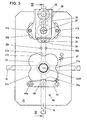
- the device 2 has a mounting plate 20 on top of which a locking disk 21 is located and at the bottom a cam disc 23 and a gear 33 are located, wherein the locking disc 21, the cam plate 23 and the gear 33 keyed onto a shaft journal 24 are, which is coupled with the shaft 13 of the rotary star 12 on entrainment and which is rotatably supported by a bearing 25 in the mounting plate 20. Furthermore, on the top of the mounting plate 20, a support plate 26 about a shaft 27 mounted pivotally. On the support plate 26 is a drive motor 28, which is coupled by means of a gear 29 with the shaft 27 on entrainment.
- a pinion 31 is pressed onto the shaft 27, which is coupled via a toothed belt 32 with the gear 33 on entrainment is.
- a bolt 34 From the support plate 26 projects from a bolt 34, which is the mounting plate 20 penetrated in a recess 30.
- Ratchet disc 36 On the underside of the mounting plate 20 is a rotatably mounted about an axis 35 Ratchet disc 36 is provided, which is formed with a slot 37, in which protrudes the bolt 34.
- the ratchet disk 36 is provided with two stops 36a and 36b formed on the cam plate 23 arranged cam 23a assigned.
- the cams 23a are arranged in pairs, with the cams 23a of a pair are located at an angular distance of about 30 ° from each other and the angular distance to the next cam 23a of the next pair is about 60 °.
- the two stops 36a and 36b are each assigned a sensor 38a or 38b.
- the shaft 27 is mounted on a carriage 27 a, which is guided in a slot 27 b located in the mounting plate 20.
- the toothed belt 32 can be tensioned.
- two bolts 41a and 41b are provided on the support plate 26, which in guide slots 40a, 40b, which are provided in the mounting plate 20, protrude. Between one of the bolts 41a and 41b and this on the mounting plate 20 associated bolts 42a and 42b further tension springs 43a and 43b may be provided.
- the latching disc 21 is a locking lever 44 pivotable about an axis 44a assigned, which is formed with a latching roller 45 and which by means of a Tension spring 47 cooperates with the notches 21 a of the locking disc 21.
- the catches 21a are located at an angular distance of 90 °. Between the notches 21 a are part-circular projections 21 b.
- the end position of the locking lever 44 is detectable by means of a sensor 48.
- the end positions of the pawl disk 36 can be detected by means of the two sensors 38a, 38b.
- One sensor 38a monitors one end position and the other sensor 38b monitors the other end position of the pawl disc 36.
- the stop surface 36b moves away from the left Sensor 38b, whereby from this a signal is emitted, through which the drive motor 28 is put back into operation.
- the support plate 26 is again pivoted clockwise to its stop and is the ratchet disk 36 pivoted counterclockwise.
- the electronic control unit is the left sensor 38b controlled so that no signal is emitted by this.
- the support plate 26 projecting bolts 41 a and 41 b at the ends of the slots 40 a and 40b, in which they are guided, get in the sequence, as shown in Fig.9 is shown, by the drive motor 28, via the gear 29, the gear 31st and the toothed belt 32, the gear 33 and with this the locking disk 21 is rotated, wherein the applied by the tension spring 47 on the locking lever 44 locking force is overcome and the detent roller 45 out of the catch 21 a.
- the rotation of the pawl disc 36 of the right stop 36a from the path of movement the cam 23a has been moved out can also be the cam Twist 23 about 30 °.
- one of the cams 23a subsequently runs on the inside of the left stop 36b of the pawl disk 36.
- the pawl disc 36 is rotated clockwise, whereby it enters the position shown in FIG. If this middle position is slightly exceeded, the backstop becomes active.
- a control signal is emitted from the sensor 48 assigned to the detent lever 44 to the electronic control unit, whereby the drive motor 28 is switched off by the electronic control unit.
- the drive motor 28 fulfills the function of an electrically controllable brake by being operated as a generator, whereby the movement of the rotary star 12 is damped in its end position. In this position, which is shown in Fig. 12, the locking disc 21 is held by the standing under the action of the tension spring 47 locking lever 44 again in their position until the drive motor 28 is turned on by the electronic control unit for the next movement.
- tension spring 43a and 43b are used to ensure that in the event of a power failure Cam plate 23 in one or the other direction is rotatable, whereby a rotation of the rotary star 12 without engagement of the drive motor 28th is possible. In this way, it is predetermined in which way the mechanics Power failure works. As long as none of the two tension springs 43a, 43b is provided, is the turnstile 12 by force in both counterclockwise and in the Locked clockwise.
- Function control is provided by an electronic control unit 10, by means of which by coins, tokens or by other effected signals to the drive motor 28, a control signal is issued to the effect that the drive motor 28 is switched on or off.
- the drive motor 28 is a pivoting of the support plate 26, on which the drive motor 28 is located.
- an opposite pivoting of the pawl disc 36 By pivoting the support plate 26, an opposite pivoting of the pawl disc 36. This is done either blocking the cam plate 23 with respect to their rotation or a release of the same.
- signals are transmitted by a pivoting of the pawl disc 36 via the sensors 38a and 38b to the control unit 10, by which a shutdown or an activation of the drive motor 28 is effected.
- a rotary star with four arms can also be one with a changed Number of arms, in particular with three arms. Furthermore you can these arms should be aligned obliquely inclined with respect to the axis of rotation.
- the particular advantage of a design according to the application is that for the motion control only arranged on a pivotable carrier Drive motor needs to be provided, which by pivoting this Carrier a blocking or release of the rotary star occurs. This is it is not necessary to provide pawls which provide additional control require.
- the pivoting of the carrier takes place by switching on the drive motor or by a force on the rotary star, but with it then, if the drive motor is not turned on, a rotation of the rotary star is prevented.
Landscapes
- Engineering & Computer Science (AREA)
- Civil Engineering (AREA)
- Structural Engineering (AREA)
- Transmission Devices (AREA)
- Supply And Installment Of Electrical Components (AREA)
Applications Claiming Priority (2)
| Application Number | Priority Date | Filing Date | Title |
|---|---|---|---|
| AT6802004A AT413294B (de) | 2004-04-21 | 2004-04-21 | Einrichtung zur steuerung der drehbewegung des drehsternes einer drehsperre |
| AT6802004 | 2004-04-21 |
Publications (2)
| Publication Number | Publication Date |
|---|---|
| EP1589186A2 true EP1589186A2 (fr) | 2005-10-26 |
| EP1589186A3 EP1589186A3 (fr) | 2006-04-26 |
Family
ID=34637620
Family Applications (1)
| Application Number | Title | Priority Date | Filing Date |
|---|---|---|---|
| EP04450237A Withdrawn EP1589186A3 (fr) | 2004-04-21 | 2004-12-23 | Dispositif de contrôle de la rotation d'un tourniquet |
Country Status (2)
| Country | Link |
|---|---|
| EP (1) | EP1589186A3 (fr) |
| AT (1) | AT413294B (fr) |
Cited By (3)
| Publication number | Priority date | Publication date | Assignee | Title |
|---|---|---|---|---|
| RU2387782C1 (ru) * | 2009-02-11 | 2010-04-27 | Алексей Владимирович Андрианов | Турникет |
| FR3043130A1 (fr) * | 2015-10-30 | 2017-05-05 | B A Dev | Portail rotatif de controle d’acces |
| GB2601611A (en) * | 2020-11-10 | 2022-06-08 | Meesons A I Ltd | Improvements to security apparatus |
Family Cites Families (2)
| Publication number | Priority date | Publication date | Assignee | Title |
|---|---|---|---|---|
| AT390996B (de) * | 1989-01-26 | 1990-07-25 | Skidata Gmbh | Drehkreuz |
| DE4007303C2 (de) * | 1990-03-08 | 1996-03-21 | Gallenschuetz E Metallbau | Sicherheitspersonenschleuse |
-
2004
- 2004-04-21 AT AT6802004A patent/AT413294B/de not_active IP Right Cessation
- 2004-12-23 EP EP04450237A patent/EP1589186A3/fr not_active Withdrawn
Cited By (4)
| Publication number | Priority date | Publication date | Assignee | Title |
|---|---|---|---|---|
| RU2387782C1 (ru) * | 2009-02-11 | 2010-04-27 | Алексей Владимирович Андрианов | Турникет |
| FR3043130A1 (fr) * | 2015-10-30 | 2017-05-05 | B A Dev | Portail rotatif de controle d’acces |
| GB2601611A (en) * | 2020-11-10 | 2022-06-08 | Meesons A I Ltd | Improvements to security apparatus |
| GB2601611B (en) * | 2020-11-10 | 2025-06-11 | Meesons A I Ltd | Improvements to security apparatus |
Also Published As
| Publication number | Publication date |
|---|---|
| AT413294B (de) | 2006-01-15 |
| EP1589186A3 (fr) | 2006-04-26 |
| ATA6802004A (de) | 2005-06-15 |
Similar Documents
| Publication | Publication Date | Title |
|---|---|---|
| DE4108641C2 (de) | Elektromotorischer Antrieb für eine Zentralverriegelungsvorrichtung an einem Kraftfahrzeug | |
| EP0718460B1 (fr) | Tourniquet | |
| EP2225430B1 (fr) | Dispositif de verrouillage d'une porte | |
| DE3545869A1 (de) | Fahrzeugdach | |
| EP2357124B1 (fr) | Serrure à deux roues | |
| DE69312560T2 (de) | Automatische Arretiervorrichtung für den elektronischen Motorantrieb von Türen, Fensterläden, Rolläden und dergleichen | |
| WO2013139873A1 (fr) | Module d'entraînement pour une porte louvoyante-coulissante d'un véhicule ferroviaire et procédé pour faire fonctionner celui-ci | |
| AT413294B (de) | Einrichtung zur steuerung der drehbewegung des drehsternes einer drehsperre | |
| EP2171202B1 (fr) | Tourniquet | |
| EP0456649B1 (fr) | Tourniquet | |
| DE2758971A1 (de) | Drehkreuz, das personen das durchschreiten eines vorgegebenen durchgangs in nur einer richtung gestattet | |
| EP0688930B1 (fr) | Serrure pour portes ou fenêtres | |
| DE3432274A1 (de) | Vorrichtung zur ver- und entriegelung von drehkreuzen | |
| EP1596352B1 (fr) | Dispositif d'affichage variable pour panneaux de signalisation | |
| DE1212809B (de) | Schrittschaltwerk | |
| DE3203151A1 (de) | Antriebsvorrichtung fuer einen verstellmechanismus eines fahrzeugsitzes | |
| EP0410299B1 (fr) | Dispositif de verrouillage et tourniquet pourvu d'un tel dispositif | |
| DE102010035555A1 (de) | Elektromotorischer Schwenkantrieb, insbesondere für Klappen, beispielsweise an Möbeln | |
| EP2129857A1 (fr) | Unité de verrouillage conçue pour un dispositif de tourniquet | |
| EP0133219B1 (fr) | Dispositif commutateur à programme | |
| DE729696C (de) | Stufenschienensteuerung fuer sprungweise schaltbare Vielzaehlwerktrommeln, die durch eine besondere Kraftquelle angetrieben werden | |
| CH704929B1 (de) | Personenschleuse. | |
| AT201121B (de) | Zählwerk mit Zahlenrollen für Telephongebührenmelder | |
| DE3037287A1 (de) | Rastenwerk | |
| DE1474646C3 (de) | Einrichtung zur elektromechanischen Um Wandlung von binar verschlüsselten Werten in Dezimalwerte |
Legal Events
| Date | Code | Title | Description |
|---|---|---|---|
| PUAI | Public reference made under article 153(3) epc to a published international application that has entered the european phase |
Free format text: ORIGINAL CODE: 0009012 |
|
| AK | Designated contracting states |
Kind code of ref document: A2 Designated state(s): AT BE BG CH CY CZ DE DK EE ES FI FR GB GR HU IE IS IT LI LT LU MC NL PL PT RO SE SI SK TR |
|
| AX | Request for extension of the european patent |
Extension state: AL BA HR LV MK YU |
|
| PUAL | Search report despatched |
Free format text: ORIGINAL CODE: 0009013 |
|
| AK | Designated contracting states |
Kind code of ref document: A3 Designated state(s): AT BE BG CH CY CZ DE DK EE ES FI FR GB GR HU IE IS IT LI LT LU MC NL PL PT RO SE SI SK TR |
|
| AX | Request for extension of the european patent |
Extension state: AL BA HR LV MK YU |
|
| AKX | Designation fees paid | ||
| REG | Reference to a national code |
Ref country code: DE Ref legal event code: 8566 |
|
| STAA | Information on the status of an ep patent application or granted ep patent |
Free format text: STATUS: THE APPLICATION IS DEEMED TO BE WITHDRAWN |
|
| 18D | Application deemed to be withdrawn |
Effective date: 20060427 |