EP1589338A2 - Procédé pour diminuer les dégats aux installations de chauffage et combustibles liquides pauvres en soufre - Google Patents
Procédé pour diminuer les dégats aux installations de chauffage et combustibles liquides pauvres en soufre Download PDFInfo
- Publication number
- EP1589338A2 EP1589338A2 EP05013646A EP05013646A EP1589338A2 EP 1589338 A2 EP1589338 A2 EP 1589338A2 EP 05013646 A EP05013646 A EP 05013646A EP 05013646 A EP05013646 A EP 05013646A EP 1589338 A2 EP1589338 A2 EP 1589338A2
- Authority
- EP
- European Patent Office
- Prior art keywords
- fuel
- oil
- sulfur
- heating
- combustion
- Prior art date
- Legal status (The legal status is an assumption and is not a legal conclusion. Google has not performed a legal analysis and makes no representation as to the accuracy of the status listed.)
- Pending
Links
- 239000000446 fuel Substances 0.000 title claims abstract description 95
- 238000010438 heat treatment Methods 0.000 title claims abstract description 39
- 239000007788 liquid Substances 0.000 title claims abstract description 12
- 238000000034 method Methods 0.000 title claims description 20
- 239000005864 Sulphur Substances 0.000 title 1
- 238000009434 installation Methods 0.000 title 1
- 230000003628 erosive effect Effects 0.000 claims abstract description 33
- 229910052717 sulfur Inorganic materials 0.000 claims abstract description 27
- 239000011593 sulfur Substances 0.000 claims abstract description 27
- NINIDFKCEFEMDL-UHFFFAOYSA-N Sulfur Chemical compound [S] NINIDFKCEFEMDL-UHFFFAOYSA-N 0.000 claims abstract description 16
- 239000003963 antioxidant agent Substances 0.000 claims abstract description 8
- 239000002283 diesel fuel Substances 0.000 claims abstract 8
- 230000003078 antioxidant effect Effects 0.000 claims abstract 4
- 238000002485 combustion reaction Methods 0.000 claims description 29
- 239000000295 fuel oil Substances 0.000 claims description 17
- 239000003921 oil Substances 0.000 claims description 15
- 239000000654 additive Substances 0.000 claims description 8
- 230000015572 biosynthetic process Effects 0.000 claims description 6
- 150000001732 carboxylic acid derivatives Chemical class 0.000 claims description 6
- 230000000996 additive effect Effects 0.000 claims description 5
- 230000003068 static effect Effects 0.000 claims description 3
- 239000002816 fuel additive Substances 0.000 claims 1
- 230000002265 prevention Effects 0.000 claims 1
- 238000012360 testing method Methods 0.000 abstract description 87
- 239000007921 spray Substances 0.000 abstract description 3
- 230000002950 deficient Effects 0.000 abstract 3
- 229910000851 Alloy steel Inorganic materials 0.000 abstract 1
- 239000002184 metal Substances 0.000 description 19
- 229910052751 metal Inorganic materials 0.000 description 19
- 238000010998 test method Methods 0.000 description 12
- 230000005684 electric field Effects 0.000 description 8
- 229910044991 metal oxide Inorganic materials 0.000 description 7
- 150000004706 metal oxides Chemical class 0.000 description 7
- OKTJSMMVPCPJKN-UHFFFAOYSA-N Carbon Chemical compound [C] OKTJSMMVPCPJKN-UHFFFAOYSA-N 0.000 description 4
- 229910052799 carbon Inorganic materials 0.000 description 4
- 239000002828 fuel tank Substances 0.000 description 4
- 229910045601 alloy Inorganic materials 0.000 description 3
- 239000000956 alloy Substances 0.000 description 3
- 238000001816 cooling Methods 0.000 description 3
- 230000007797 corrosion Effects 0.000 description 3
- 238000005260 corrosion Methods 0.000 description 3
- 150000002500 ions Chemical class 0.000 description 3
- 239000003595 mist Substances 0.000 description 3
- 229910052760 oxygen Inorganic materials 0.000 description 3
- 239000001301 oxygen Substances 0.000 description 3
- 239000012071 phase Substances 0.000 description 3
- 238000005507 spraying Methods 0.000 description 3
- 238000009423 ventilation Methods 0.000 description 3
- UQSXHKLRYXJYBZ-UHFFFAOYSA-N Iron oxide Chemical compound [Fe]=O UQSXHKLRYXJYBZ-UHFFFAOYSA-N 0.000 description 2
- 235000009781 Myrtillocactus geometrizans Nutrition 0.000 description 2
- 240000009125 Myrtillocactus geometrizans Species 0.000 description 2
- -1 Oxygen carboxylic acid Chemical class 0.000 description 2
- 239000003245 coal Substances 0.000 description 2
- 239000000567 combustion gas Substances 0.000 description 2
- 238000001704 evaporation Methods 0.000 description 2
- 230000008020 evaporation Effects 0.000 description 2
- 239000000463 material Substances 0.000 description 2
- 238000005259 measurement Methods 0.000 description 2
- 238000002156 mixing Methods 0.000 description 2
- 238000009736 wetting Methods 0.000 description 2
- 241001156002 Anthonomus pomorum Species 0.000 description 1
- CWYNVVGOOAEACU-UHFFFAOYSA-N Fe2+ Chemical compound [Fe+2] CWYNVVGOOAEACU-UHFFFAOYSA-N 0.000 description 1
- QVGXLLKOCUKJST-UHFFFAOYSA-N atomic oxygen Chemical compound [O] QVGXLLKOCUKJST-UHFFFAOYSA-N 0.000 description 1
- 230000009286 beneficial effect Effects 0.000 description 1
- 238000009833 condensation Methods 0.000 description 1
- 230000005494 condensation Effects 0.000 description 1
- 239000004035 construction material Substances 0.000 description 1
- 238000013461 design Methods 0.000 description 1
- 238000006477 desulfuration reaction Methods 0.000 description 1
- 230000023556 desulfurization Effects 0.000 description 1
- 239000000428 dust Substances 0.000 description 1
- 230000000694 effects Effects 0.000 description 1
- 239000003344 environmental pollutant Substances 0.000 description 1
- 238000002474 experimental method Methods 0.000 description 1
- 230000004907 flux Effects 0.000 description 1
- 238000007689 inspection Methods 0.000 description 1
- 238000011835 investigation Methods 0.000 description 1
- 238000010849 ion bombardment Methods 0.000 description 1
- 239000007791 liquid phase Substances 0.000 description 1
- 238000012544 monitoring process Methods 0.000 description 1
- 230000007935 neutral effect Effects 0.000 description 1
- 239000003129 oil well Substances 0.000 description 1
- 231100000719 pollutant Toxicity 0.000 description 1
- 238000007142 ring opening reaction Methods 0.000 description 1
- 238000004904 shortening Methods 0.000 description 1
- 239000010935 stainless steel Substances 0.000 description 1
- 229910001220 stainless steel Inorganic materials 0.000 description 1
- 239000000126 substance Substances 0.000 description 1
- 230000002459 sustained effect Effects 0.000 description 1
- 238000012549 training Methods 0.000 description 1
- 239000012808 vapor phase Substances 0.000 description 1
Images


Classifications
-
- G—PHYSICS
- G01—MEASURING; TESTING
- G01N—INVESTIGATING OR ANALYSING MATERIALS BY DETERMINING THEIR CHEMICAL OR PHYSICAL PROPERTIES
- G01N33/00—Investigating or analysing materials by specific methods not covered by groups G01N1/00 - G01N31/00
- G01N33/26—Oils; Viscous liquids; Paints; Inks
- G01N33/28—Oils, i.e. hydrocarbon liquids
- G01N33/2817—Oils, i.e. hydrocarbon liquids using a test engine
-
- G—PHYSICS
- G01—MEASURING; TESTING
- G01N—INVESTIGATING OR ANALYSING MATERIALS BY DETERMINING THEIR CHEMICAL OR PHYSICAL PROPERTIES
- G01N17/00—Investigating resistance of materials to the weather, to corrosion, or to light
-
- G—PHYSICS
- G01—MEASURING; TESTING
- G01N—INVESTIGATING OR ANALYSING MATERIALS BY DETERMINING THEIR CHEMICAL OR PHYSICAL PROPERTIES
- G01N31/00—Investigating or analysing non-biological materials by the use of the chemical methods specified in the subgroup; Apparatus specially adapted for such methods
- G01N31/12—Investigating or analysing non-biological materials by the use of the chemical methods specified in the subgroup; Apparatus specially adapted for such methods using combustion
Definitions
- low-sulfur heating oils have come on the market, the one Having a sulfur content of 0.05 to 0.001%.
- Such low-sulfur heating oils occur previously unknown damage to the Metal parts in the boiler room and the oil burner, especially on the flame cup on.
- the damage also occurs in condensing heating systems, which the Use condensation heat and with low-temperature burners, so-called fan blue burners are equipped.
- the damage pictures show sharply outlined, crater-shaped eroded areas with a finely grained surface and distinguish distinct from high-temperature corrosion. Such damage can within a few weeks of start-up of the heating system arise.
- the choice of more corrosion-resistant materials has only limited Influence on the damage pictures.
- the liquid, low-sulfur fuel e.g. batch through a neutral body or in the refinery, to its potential erosive To test the effect of burning in heating systems.
- To examine the Fuel will advantageously be the fuel in combustion air near one Test area fogged and the fuel mist an electric field of tension exposed and inflamed.
- Temperature range is necessary. This temperature range is safe between 350 and 600 ° C. A limited temperature range is between 370 and 550 ° C. In this temperature range, the processes occur, the damage pattern cause. Due to further investigations this temperature range is possibly even more precise restrictable. It could be further observed that the damage patterns accelerate in places that occur due to the fuel be wetted.
- the one has suitable temperature for starting.
- Once the combustion process heat developed, is advantageously converted to cooled fuel oil.
- the cooled fuel oil may advantageously be mixed with a flow improver to keep it as cool as possible, e.g. can be used at minus 10 ° C. Thanks to a cooled fuel will wetted the test area as long as possible.
- the above sequence can be advantageously supplemented with a further process step in which existing test areas are cooled.
- To cool down Turning off the fuel supply is advantageously used air.
- a metal test surface used. This is expediently from a suitable for burner construction Material, eg. B. Alloy 601 manufactured.
- the test surface is advantageously in a burner, e.g. used in an evaporator.
- the test surface may be the inner surface of a Flammbechers be. It can also be the surface of an evaporator. she can in particular also be a surface of a conventional burner.
- the ignition is advantageously carried out by a spark.
- the electrodes can be supplied with an AC voltage, or a constant potential difference exhibit.
- the stress field can be built up between two electrodes, while the test area is grounded. It can also be between an electrode and the Test surface are constructed so that the test surface forms an electrode.
- These the Test surface forming electrode is advantageously made of flat material.
- an oil supply is done according to regulations only after one Pre-ignition time of 10 to 15 seconds. This can in the inventive Test methods are handled as well. It is essential that the plasma one are exposed to electrical stress. Preferably, the stress field already built up during the emergence of the flame.
- the electrodes or the electrode is advantageous in a distance of less than 50 mm, advantageously at a distance of less than 15 mm, or even at a distance of 3 to 7 mm from the metal test surface, or the location of the test area near which the ionization of the fuel occurs.
- the Voltage and the distance between the voltage potentials are each other Accordingly, reciprocally to choose such that the largest possible volume of the Plasma is exposed to the highest possible voltage.
- the plasma advantageously becomes a voltage of 2 times 7500 V and more, preferably at least 2 times 10'000 V, especially preferably exposed to at least 2 times 15,000 volts. It could be determined, however be that individual fuels already at voltages of 200 V or 230 V. Cause damage.
- the test method an advantageous in Flame area arranged metal surface sprayed with the fuel oil or even wetted. So that the ionization of the fuel as long as possible near the test area occurs, the Flammbecher or another test area before the beginning of a new sequence advantageous to a temperature below 250 ° C, preferably below 220 ° C, more preferably cooled below 200 ° C. A cooling happens preferably by post-ventilation for a few seconds or minutes.
- the Test surface is advantageously arranged axially in the fresh air flow for the purpose of cooling.
- the test surface is cooled during the entire burning time.
- the cooling between the sequences below 250 degrees is achieved at the Next, the test area has a temperature range of 350 to 550 or 600 ° C has to go through.
- the sequence length is achieved that the Test area reached 550 to 600 degrees, however, the process did not last unnecessarily long Higher and therefore less efficient temperatures continue.
- a sequence is chosen short so that it takes less than 15 minutes advantageously less than 10 minutes, more preferably less than 5 Minutes. As a result, the erosion-effective time share per hour can be increased.
- a fuel oil sample can be within a maximum of 30 to 40 operating hours (burning time) to be checked for their eroding effect. It It is expected that by optimizing the test procedure this operating time can be shortened even further. Depending on the properties of the sample, a first occurs erosion visible to the naked eye after only a few hours of operation.
- test area An eroded or after e.g. 40 hours still not eroded test area is conveniently archived as a record of the fuel oil quality of a batch. For everyone too testing batch will therefore be beneficial to a new test area in one Test device arranged.
- This test surface can be preceded by a Coal layer be provided. But it can also start the process Combustion be influenced so that a layer of carbon on the Test surface forms.
- a Device having at least the following: One Fuel tank for a fuel sample, one to the fuel tank connected fuel pump, one arranged after the fuel pump Nozzle for spraying fuel, a voltage converter, at least one connected to the voltage converter electrode, a fan for a Fresh air supply, a control for controlling the fuel pump, the Voltage converter and the fan, as well as a simple out of the device Removable and applicable in the device test surface.
- a Device may lack a firebox or boiler altogether.
- a temperature sensor for measuring the temperature of the test area available.
- the test surface is advantageously metallic and preferably with a Provided carbon film.
- test area becomes advantageous before the test procedure treated with a metal oxide.
- the test area can also be treated with metal dust which then oxidizes upon combustion of fuel.
- the controller is advantageously designed so that it a variety of automatically controls the sequences described.
- the voltage converter is advantageously dimensioned such that it has a Voltage of twice more than 7,500 V, preferably twice more than 10,000 V, particularly preferably generated by twice more than 15,000 volts.
- conventional Voltage transformers for heating systems are at a voltage of twice 7500 Volts, a pre-ignition of 12 sec. And a Nachzündzeit of about 20 sec. Designed.
- the Voltage can also be built up against the earth as the second potential. It may also, at most in addition to the voltage between the electrodes, a constant potential difference between a separate electrode and grounded or under tensioned test surface. It can also the test surface is put under tension with respect to the earth.
- the electrode is, or the electrodes are advantageously at a distance of less than 50 mm, advantageously at a distance of less than 15 mm from one metal test surface arranged.
- a temperature sensor is available with which the temperature of the test area can be monitored.
- the nozzle and the test surface are advantageously arranged and the nozzle has a such characteristic that it is ensured that the fuel is resistant to the Area of flame arranged test surface sprays and the fuel the test surface wetted and passes into a plasma near the test area. It can be a first nozzle for a flame maintaining fuel supply to the flame and a second Nozzle for spraying or wetting the test surface be present.
- the metal ones Test surface is advantageously made of a stainless steel, e.g. Alloy 601, DIN 2.4851, which ensures that no high-temperature corrosion occurs. This is one damage pattern clearly reflects the erosion and quality of the tested Attributable to fuel.
- antioxidants are added. Prevent antioxidants, like also a sulfur content of over 0.4 to 0.5% m / m, the formation of carboxylic acid.
- an additive can be added to the heating oil, which ensures that the Electrostatic charges remain low during combustion.
- Such a "static Dissipator additives” is for example the so far used in Klibezin" Stadis 450 ". Whether the dosage of the additives is sufficient is advantageous by means of the tested test method.
- Another measure to prevent the erosion described is to to ignite the fuel with a glow ignition and so the electric Keep voltage in the combustion chamber as low as possible.
- An advantageous blue flame burner is therefore with a glow ignition, in particular with a low-voltage glow ignition equipped. This prevents large numbers of ions in one Stress field can be accelerated, impact the metal and thereby its Erode surface.
- the burner 11 according to Figure 1 has a fuel pump 13, with the Fuel from a container, not shown, the fuel nozzle 15 is pumped becomes.
- the fuel nozzle 15 is with its nozzle opening approximately in the plane of a Baffle plate 17 arranged.
- In the baffle plate 17 is a central opening present, through which the fuel can be injected into an evaporator 19.
- the evaporator 19 is arranged in a flame tube 21.
- the burner 11 also has a fan 23. With the fan 23 can Fresh air with a certain pressure to the baffle plate 17 are introduced. The fresh air enters the sequence in the interior of the evaporator 19, where they are mixed with vaporized fuel and with recirculated combustion gases. Not shown are temperature sensors for monitoring the temperature of the Fuel and the test area. Not shown is a combustion chamber, in which the flame is burning.
- Recognizable are two ignition electrodes 25 near the Vergaserwandung. These are on a voltage transformer, not shown, connected to the electrodes with an alternating potential difference of twice 7500 volts supplied.
- the evaporator 19 is shown in FIGS. 2 to 4. He instructs Evaporator tube 31 and a flame divider 33 on.
- the flame divider 33 is with three legs 35 attached to the evaporator tube.
- the attachment happens over Sheet metal tabs 37, which are formed on the legs 35 and in slots on Insert evaporator tube 31. These inserted metal tabs 37 can be 20 to 30 ° are rotated and are thus mechanically fixed to the evaporator tube 31 connected.
- the evaporator tube 31 to the baffle plate 39 by means of three in Slot stuck and twisted metal tabs 37 attached. That's it Evaporator tube 31 very easy to insert into the baffle plate 39 and again from the Baffle plate 39 removable.
- baffle plate 39 For the ignition of the fuel, two electrodes 25 are provided by the Baffle plate 39 are passed. In the baffle plate 39 is also an opening 43 for a temperature sensor available.
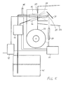
- FIG. 5 schematically shows an advantageous device for testing liquid fuel, especially fuel oil on its potential erosive effect when burning in a heating system shown.
- This one has one Fuel tank 45 for a fuel sample, one to the fuel tank 45th connected fuel pump 13 and two after the fuel pump 13th arranged nozzles 15, 16.
- the first nozzle 15 has a cone characteristic a common angle for spraying fuel.
- the second nozzle 16 Fuel injects fuel specifically to the test area 31. It has a characteristic with it a sharp cone angle of a few degrees.
- a Voltage converter 47 and one connected to the voltage converter 47 Electrode 25 available.
- a fan 23 for a fresh air supply and a Control 51 for controlling the fuel pump 13, the voltage converter 47th and the fan 23 complete the testing apparatus.
- a replaceable metal test surface 31 in FIG Arranged area of the flame This is grounded.
- a temperature sensor 49 the oil temperature can be monitored.
- an infrared sensor 50 the Temperature of the test area 31 are monitored.
- the flame is a combustion chamber within a combustion chamber wall 53 present, whose design is of minor importance. So that Flame burns quietly, a flame tube 55 is available.
- the fresh air is through the Blower 23 is blown against a baffle plate 57.
- This has a central Air opening in which the first nozzle is arranged such that around the first nozzle 15 there is a ring opening.
- Axial in the flow direction of the air is the Test area 31 is arranged. Near and in front of the test area 31 is an electrode 25 arranged with, for example, 12,000 volts DC or AC voltage the current transformer 47 can be provided.
- the second nozzle 16 is on the Test surface 31 directed, in such a way that the injected through the second nozzle Fuel approximately centrally impinges on the test surface 31 and wets them. Thus is this location of the test area 31 by the air flow and the wetting fuel cooled. It is in the immediate vicinity of or in the field of tension strong exposed area of the plasma. This spot is also illuminated by the infrared sensor supervised.
- the controller 51 may after a timer regularly the fan 23, the Oil pump 13, possibly an unillustrated valve for controlling the nozzles 15,16 and drive the current transformer 47. You can also do this because of Control fair values.
- the measured value is in particular the temperature of the Test area 31 in question. So the test procedure sequence can be started as soon as the temperature sensor of the test area, for example 250, 300, 350 or 380 degrees measures. The sequence can be terminated if the test area is 550, 600 or 650 Degree measures.
- the fuel may also be applied to a test area be applied, which is electrically preheated.
- the test area can be off consist of an Alloy strip, which is connected to a power source and so on directly heated or indirectly heated with a heating coil.
- the fuel can be poured onto the test surface, dropped or sprayed on.
- the Evaporation or evaporation of the fuel takes place thanks to the Heat energy supply to the test area. This allows the test surface to be controlled to run repeatedly through the desired temperature profile.
- a fuel sample checked.
- the fuel with the nozzle 15 in the Carburetor tube 31 sprayed.
- the fuel becomes thanks to existing Residual heat or the energy supplied to the electrodes gassed and am Spark ignited.
- the plasma is a electrical voltage field of twice 7500 volts alternating voltage exposed. Thanks to the low sulfur content, the presence of the blower are injected oxygen-rich fresh air and the electric field the combustion conditions such that eroded at the carburetor 31 very quickly Jobs arise.
- a preferred sequence has 2 minutes burn time, that of 3 minutes Afterbreathing is followed.
- the Vorzündzeit overlaps the Nachlstructurezeit and is short, for example 2 seconds.
- the fuel pump will start for 2 minutes, during which the grounded test surface is sprayed.
- the oil supply is a voltage of about 15,000 volts from the earth on the given only electrode.
- the errosivity of the fuel can be at this Test equipment to be assessed after about 3 days of the trial period.
Landscapes
- Chemical & Material Sciences (AREA)
- Health & Medical Sciences (AREA)
- Engineering & Computer Science (AREA)
- Life Sciences & Earth Sciences (AREA)
- Analytical Chemistry (AREA)
- Biochemistry (AREA)
- General Chemical & Material Sciences (AREA)
- Food Science & Technology (AREA)
- Medicinal Chemistry (AREA)
- Physics & Mathematics (AREA)
- Chemical Kinetics & Catalysis (AREA)
- Oil, Petroleum & Natural Gas (AREA)
- General Health & Medical Sciences (AREA)
- General Physics & Mathematics (AREA)
- Immunology (AREA)
- Pathology (AREA)
- Investigating Or Analyzing Materials Using Thermal Means (AREA)
- Heating, Cooling, Or Curing Plastics Or The Like In General (AREA)
- Heat Treatments In General, Especially Conveying And Cooling (AREA)
- Heat Treatment Of Articles (AREA)
Priority Applications (1)
| Application Number | Priority Date | Filing Date | Title |
|---|---|---|---|
| EP05013646A EP1589338A2 (fr) | 2001-09-21 | 2002-09-23 | Procédé pour diminuer les dégats aux installations de chauffage et combustibles liquides pauvres en soufre |
Applications Claiming Priority (4)
| Application Number | Priority Date | Filing Date | Title |
|---|---|---|---|
| EP01810927 | 2001-09-21 | ||
| EP01810927 | 2001-09-21 | ||
| EP05013646A EP1589338A2 (fr) | 2001-09-21 | 2002-09-23 | Procédé pour diminuer les dégats aux installations de chauffage et combustibles liquides pauvres en soufre |
| EP02762199A EP1466171B1 (fr) | 2001-09-21 | 2002-09-23 | Procede pour reduire les deteriorations au niveau d'installations de chauffage et dispositif pour mettre ledit procede en oeuvre |
Related Parent Applications (2)
| Application Number | Title | Priority Date | Filing Date |
|---|---|---|---|
| EP02762199.4 Division | 2002-09-23 | ||
| EP02762199A Division EP1466171B1 (fr) | 2001-09-21 | 2002-09-23 | Procede pour reduire les deteriorations au niveau d'installations de chauffage et dispositif pour mettre ledit procede en oeuvre |
Publications (1)
| Publication Number | Publication Date |
|---|---|
| EP1589338A2 true EP1589338A2 (fr) | 2005-10-26 |
Family
ID=8184153
Family Applications (2)
| Application Number | Title | Priority Date | Filing Date |
|---|---|---|---|
| EP02762199A Expired - Lifetime EP1466171B1 (fr) | 2001-09-21 | 2002-09-23 | Procede pour reduire les deteriorations au niveau d'installations de chauffage et dispositif pour mettre ledit procede en oeuvre |
| EP05013646A Pending EP1589338A2 (fr) | 2001-09-21 | 2002-09-23 | Procédé pour diminuer les dégats aux installations de chauffage et combustibles liquides pauvres en soufre |
Family Applications Before (1)
| Application Number | Title | Priority Date | Filing Date |
|---|---|---|---|
| EP02762199A Expired - Lifetime EP1466171B1 (fr) | 2001-09-21 | 2002-09-23 | Procede pour reduire les deteriorations au niveau d'installations de chauffage et dispositif pour mettre ledit procede en oeuvre |
Country Status (4)
| Country | Link |
|---|---|
| EP (2) | EP1466171B1 (fr) |
| AT (1) | ATE326696T1 (fr) |
| DE (1) | DE50206846D1 (fr) |
| WO (1) | WO2003027668A1 (fr) |
Families Citing this family (3)
| Publication number | Priority date | Publication date | Assignee | Title |
|---|---|---|---|---|
| WO2005033253A1 (fr) * | 2003-10-07 | 2005-04-14 | Swiss E-Technic Ag | Huile pauvre en soufre et procede pour abaisser l'agressivite d'une telle huile |
| US20070172959A1 (en) | 2003-12-15 | 2007-07-26 | Fuellemann Joerg | Method and device for electrically testing fuels and combustibles by generating a plasma |
| DE102009006319B3 (de) * | 2009-01-27 | 2010-10-14 | Chemin Gmbh | Brennstoff-Korrosionsdiagnose |
Family Cites Families (5)
| Publication number | Priority date | Publication date | Assignee | Title |
|---|---|---|---|---|
| JPS5740652A (en) * | 1980-08-22 | 1982-03-06 | Mitsubishi Electric Corp | Corrosion property testing method for insulating oil |
| US5332961A (en) * | 1986-11-06 | 1994-07-26 | Ford Motor Company | Resistive oil quality sensor |
| US5641841A (en) * | 1995-01-10 | 1997-06-24 | International Business Machines Corporation | Conductive lubricant for magnetic disk drives |
| DE59608696D1 (de) * | 1995-08-21 | 2002-03-21 | Miele & Cie | Wäschetrockner mit einer gasbeheizten Heizungseinrichtung |
| DE10045642A1 (de) * | 2000-09-15 | 2002-04-25 | Heatec Thermotechnik Gmbh | Feuerungseinrichtung |
-
2002
- 2002-09-23 EP EP02762199A patent/EP1466171B1/fr not_active Expired - Lifetime
- 2002-09-23 DE DE50206846T patent/DE50206846D1/de not_active Expired - Fee Related
- 2002-09-23 AT AT02762199T patent/ATE326696T1/de not_active IP Right Cessation
- 2002-09-23 WO PCT/CH2002/000532 patent/WO2003027668A1/fr not_active Ceased
- 2002-09-23 EP EP05013646A patent/EP1589338A2/fr active Pending
Also Published As
| Publication number | Publication date |
|---|---|
| DE50206846D1 (de) | 2006-06-22 |
| ATE326696T1 (de) | 2006-06-15 |
| EP1466171A1 (fr) | 2004-10-13 |
| WO2003027668A1 (fr) | 2003-04-03 |
| EP1466171B1 (fr) | 2006-05-17 |
Similar Documents
| Publication | Publication Date | Title |
|---|---|---|
| DE102019117331A1 (de) | Brenner zur Erzeugung einer Flamme für die Verbrennung von Prozessgas und Abgasbehandlungsvorrichtung mit einem Brenner | |
| WO2010006723A2 (fr) | Procédé et dispositif pour allumer et faire fonctionner des brûleurs lors de la gazéification de combustibles contenant du carbone | |
| DE102008031979A1 (de) | Verfahren zur Brenngas-Luft-Einstellung für einen brenngasbetriebenen Brenner | |
| EP1013995A2 (fr) | Procédé pour le traitement thermique de liquides non inflammables | |
| DE102017107592B4 (de) | Flammen-Überwachungsanordnung für ein mit Brennstoff arbeitendes Heizgerät | |
| DE19903305C5 (de) | Verfahren zur Flammüberwachung in einem Fahrzeugheizgerät | |
| EP1466171B1 (fr) | Procede pour reduire les deteriorations au niveau d'installations de chauffage et dispositif pour mettre ledit procede en oeuvre | |
| DE851863C (de) | Verbrennungskammer mit Zuendkerzenanordnung fuer Gasturbinen mit Gleichdruckverbrennung | |
| EP4345378B1 (fr) | Procédé de mise en service d'un appareil de chauffage, appareil de commande et de régulation, appareil de chauffage et programme informatique | |
| EP3933267A1 (fr) | Procédé de surveillance d'une flamme dans une chambre de combustion de brûleur | |
| DE102005008617B3 (de) | Brenner mit Flammenüberwachung und Zündeinrichtung zum Erwärmen einer Thermoprozessanlage | |
| DE1451610B2 (de) | Vorri chtung zum Zünden und überwachen der Flammen eines Zündbrenners und eines Hauptbrenners | |
| EP4098944A1 (fr) | Procédé de surveillance d'une flamme d'un appareil chauffant, programme informatique, support d'enregistrement, appareil de régulation et de commande, appareil chauffant et utilisation d'un dispositif de positionnement | |
| DE102006060669A1 (de) | Katalytische Verdampfung von flüssigen Brennstoffen | |
| AT412419B (de) | Verfahren und eine vorrichtung zur überprüfung der zündfunktion einer zündeinrichtung | |
| EP0080184B1 (fr) | Appareil pour contrôler le danger potentiel d'un mélange gazeux composé de gaz et/ou vapeurs | |
| DE19937921B4 (de) | Verfahren und Vorrichtung zum Verdampfen eines flüssigen Brennstoffes für einen Brenner | |
| DE2237724A1 (de) | Verfahren und vorrichtung zur ueberwachung des schadstoffgehalts von verbrennungsabgasen | |
| DE2043137A1 (de) | Verfahren zur Rauchverminderung | |
| DE10312111A1 (de) | Verfahren zum Zünden eines Ölbrenners und Zündeinrichtung für eine Ölbrenneranordnung | |
| DE102012017241A1 (de) | Ölbrenner sowie Verfahren zur Regelung der Mischzonentemperatur hierzu | |
| DE2912102C2 (de) | Brenner für flüssigen Brennstoff | |
| DE690020C (de) | Sicherheitseinrichtung gegen die Folgen einer Spaet- oder Fehlzuendung bei selbsttaetig arbeitenden OElfeuerungsanlagen | |
| DE2600263A1 (de) | Verfahren und vorrichtung zum zerlegen von ammoniakgas | |
| DE2360187A1 (de) | Verbrennungskammer fuer die reinigung von verbrennungsgasen |
Legal Events
| Date | Code | Title | Description |
|---|---|---|---|
| PUAI | Public reference made under article 153(3) epc to a published international application that has entered the european phase |
Free format text: ORIGINAL CODE: 0009012 |
|
| 17P | Request for examination filed |
Effective date: 20050624 |
|
| AC | Divisional application: reference to earlier application |
Ref document number: 1466171 Country of ref document: EP Kind code of ref document: P |
|
| AK | Designated contracting states |
Kind code of ref document: A2 Designated state(s): AT BE BG CH CY CZ DE DK EE ES FI FR GB GR IE IT LI LU MC NL PT SE SK TR |
|
| STAA | Information on the status of an ep patent application or granted ep patent |
Free format text: STATUS: THE APPLICATION IS DEEMED TO BE WITHDRAWN |