EP1589504A1 - Spielautomat - Google Patents
Spielautomat Download PDFInfo
- Publication number
- EP1589504A1 EP1589504A1 EP05008748A EP05008748A EP1589504A1 EP 1589504 A1 EP1589504 A1 EP 1589504A1 EP 05008748 A EP05008748 A EP 05008748A EP 05008748 A EP05008748 A EP 05008748A EP 1589504 A1 EP1589504 A1 EP 1589504A1
- Authority
- EP
- European Patent Office
- Prior art keywords
- symbol
- displayed
- stopped
- symbols
- variable display
- Prior art date
- Legal status (The legal status is an assumption and is not a legal conclusion. Google has not performed a legal analysis and makes no representation as to the accuracy of the status listed.)
- Withdrawn
Links
- 230000000694 effects Effects 0.000 claims abstract description 21
- 238000001514 detection method Methods 0.000 claims description 15
- 238000003780 insertion Methods 0.000 claims description 14
- 230000037431 insertion Effects 0.000 claims description 14
- 241000238565 lobster Species 0.000 abstract description 44
- 230000008569 process Effects 0.000 description 98
- 238000000034 method Methods 0.000 description 90
- 239000004973 liquid crystal related substance Substances 0.000 description 40
- 241001125048 Sardina Species 0.000 description 21
- 235000019512 sardine Nutrition 0.000 description 21
- 241000251730 Chondrichthyes Species 0.000 description 18
- 235000019688 fish Nutrition 0.000 description 18
- 241000238413 Octopus Species 0.000 description 16
- 238000005070 sampling Methods 0.000 description 8
- 101100004297 Caenorhabditis elegans bet-1 gene Proteins 0.000 description 7
- 230000006870 function Effects 0.000 description 6
- 238000010586 diagram Methods 0.000 description 4
- 230000008859 change Effects 0.000 description 3
- 238000010276 construction Methods 0.000 description 3
- 241000251468 Actinopterygii Species 0.000 description 1
- 230000009286 beneficial effect Effects 0.000 description 1
- 238000012986 modification Methods 0.000 description 1
- 230000004048 modification Effects 0.000 description 1
Images










Classifications
-
- G—PHYSICS
- G07—CHECKING-DEVICES
- G07F—COIN-FREED OR LIKE APPARATUS
- G07F17/00—Coin-freed apparatus for hiring articles; Coin-freed facilities or services
- G07F17/32—Coin-freed apparatus for hiring articles; Coin-freed facilities or services for games, toys, sports, or amusements
- G07F17/34—Coin-freed apparatus for hiring articles; Coin-freed facilities or services for games, toys, sports, or amusements depending on the stopping of moving members in a mechanical slot machine, e.g. "fruit" machines
-
- G—PHYSICS
- G07—CHECKING-DEVICES
- G07F—COIN-FREED OR LIKE APPARATUS
- G07F17/00—Coin-freed apparatus for hiring articles; Coin-freed facilities or services
- G07F17/32—Coin-freed apparatus for hiring articles; Coin-freed facilities or services for games, toys, sports, or amusements
-
- G—PHYSICS
- G07—CHECKING-DEVICES
- G07F—COIN-FREED OR LIKE APPARATUS
- G07F17/00—Coin-freed apparatus for hiring articles; Coin-freed facilities or services
- G07F17/32—Coin-freed apparatus for hiring articles; Coin-freed facilities or services for games, toys, sports, or amusements
- G07F17/326—Game play aspects of gaming systems
- G07F17/3262—Player actions which determine the course of the game, e.g. selecting a prize to be won, outcome to be achieved, game to be played
-
- G—PHYSICS
- G07—CHECKING-DEVICES
- G07F—COIN-FREED OR LIKE APPARATUS
- G07F17/00—Coin-freed apparatus for hiring articles; Coin-freed facilities or services
- G07F17/32—Coin-freed apparatus for hiring articles; Coin-freed facilities or services for games, toys, sports, or amusements
- G07F17/326—Game play aspects of gaming systems
- G07F17/3262—Player actions which determine the course of the game, e.g. selecting a prize to be won, outcome to be achieved, game to be played
- G07F17/3265—Influencing the position of stopped moving members to achieve a winning arrangement, e.g. nudging, shuffling, holding
Definitions
- the present invention relates to a gaming machine in which a game is conducted by using symbols variably displayed and thereafter stopped.
- a slot machine a plurality of reels are rotated for a predetermined time and coins are paid out corresponding to a symbol combination which is displayed when all reels are stopped.
- slot machines are roughly classified based on kinds of reels, there exist a mechanical type of slot machine in which plural reels on each outer periphery of which symbols are formed are rotatably provided and a video slot machine in which a plurality of hypothetical reels (graphics of reels), which are displayed on a display device, are rotated.
- the present invention has been done and has an object to provide a gaming machine in which a display mode of symbols stopped and displayed can be changed based on an operation by a player, thereby familiarity of the player for games can be increased.
- a gaming machine having a display device for variably displaying and stopping symbols thereon and a game controller for conducting a payout corresponding to a symbol combination stopped and displayed on the display device, the gaming machine comprising:
- the display mode of the symbol stopped and displayed on the display device is changed by the symbol movement device, thereby the display mode of the symbol stopped and displayed on the display device can be changed by player's operation. Therefore, familiarity of the player for a game can be increased.
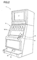
- Fig. 2 is a perspective view of the slot machine.
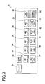
- Fig. 3 is a front view of a control panel.
- Fig 4 is a block diagram schematically showing a control system of the slot machine.
- the slot machine 1 has a cabinet 2 which forms whole construction of the slot machine 1.
- a cabinet 2 which forms whole construction of the slot machine 1.
- an upper liquid crystal display 3 is arranged and a lower liquid crystal display 4 is arranged on a device front panel 20 which is arranged at a center position of the front plane of the cabinet 2.
- both the upper liquid crystal display 3 and the lower liquid crystal display 4 are constructed from liquid crystal display generally used.
- a touch panel 121 is arranged on a surface of the lower liquid crystal display 4.
- variable display portions 21, 22, 23, 24 and 25 are basically displayed as shown in Fig. 2.
- various symbols are variably displayed while being scrolled from an upper direction toward a lower direction, thereafter stopped and displayed.
- a slot game (there exist a base game and a bonus game) is conducted through a video reels which are realized by displaying variable display portions 21 to 25 on the lower liquid crystal display 4.
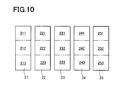
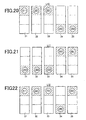
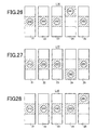
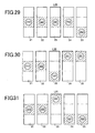
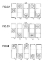
- the slot game there exist three symbols stopped and displayed on each of the variable display portions 21 to 25. That is to say, as shown in Fig. 10, the variable display portions 21 to 25 are divided into first stop areas 211, 221, 231, 241, 251, second stop areas 212, 222, 232, 242, 252, and third stop areas 213, 223, 233, 243, 253. And the symbols are respectively stopped and displayed on the stop areas 211 - 213, 221 - 223, 231 - 233, 241 - 243, 251 - 253.
- the first pay line L1 is formed from the second stop areas 212, 222, 232, 242, 252.
- the second pay line L2 is formed from the first stop areas 211, 221, 231, 241, 251.
- the third pay line L3 is formed from the third stop areas 213, 223, 233, 243, 253.
- the fourth pay line L4 is formed from the first stop areas 211, 221, 231, 241 and the third stop area 253.
- the fifth pay line L5 is formed from the first stop area 251 and the third stop areas 213, 223, 233, 243.
- the sixth pay line L6 is formed from the first stop areas 211, 221, 231, 241 and the second stop area 252.
- the seventh pay line L7 is formed from the second stop area 252 and the third stop areas 213, 223, 233, 243.
- the eighth pay line L8 is formed from the first stop areas 211, 221, 231, 251 and the second stop area 242.
- the ninth pay line L9 is formed from the second stop area 242 and the third stop areas 213,223, 233, 253.
- the tenth pay line L10 is formed from the first stop areas 211, 221, 231 and the third stop areas 243, 253.
- the eleventh pay line L11 is formed from the first stop areas 241, 251 and the third stop areas 213, 223, 233.
- the twelfth pay line L12 is formed from the first stop areas 211, 221, 231, 151 and the third stop area 243.
- the thirteenth pay line L13 is formed from the first stop area 241 and the third stop areas 213, 223, 233, 253.
- the fourteenth pay line L14 is formed from the first stop areas 241, 251 and the second stop areas 212, 222, 232.
- the fifteenth pay line L15 is formed from the second stop areas 212, 222, 232 and the third stop areas 243, 253.
- the sixteenth pay line L16 is formed from the first stop area 241 and the second stop areas 212, 222, 232, 252.
- the seventeenth pay line L17 is formed from the second stop areas 212, 222, 232, 252 and the third stop area 243.
- the eighteenth pay line L18 is formed from the first stop area 251 and the second stop areas 212, 222, 232, 242.
- the nineteenth pay line L19 is formed from the second stop areas 212, 222, 232, 242 and the third stop area 253.
- the twentieth pay line L20 is formed from the first stop areas 241, 251 and the second stop areas 212, 222 and the third stop area 233.
- the twenty-first pay line L21 is formed from the first stop area 231 and the second stop areas 212, 222 and the third stop areas 243, 253.
- the twenty-second pay line L22 is formed from the first stop areas 221, 241 and the second stop area 212 and the third stop areas 233, 253.
- the twenty-third pay line L23 is formed from the first stop areas 231, 251 and the second stop area 212 and the third stop areas 223, 243.
- the twenty-fourth pay line L24 is formed from the first stop areas 211, 231 and the third stop areas 223, 243, 253.
- the twenty-fifth pay line L25 is formed from the first stop areas 221, 241, 251 and the third stop areas 213, 233.
- the pay line (s) activated among the 25 pay lines is/are called as "activated pay line (s)"
- a control panel 5 which is projected forward is formed.
- a COLLECT button 31 and a GAME RULES button 32 are arranged in an upper step from the most left side, and a BET 1 PER LINE button 33, a BET 2 PER LINE button 34, a BET 3 PER LINE button 35, a BET 5 PER LINE button 36, a BET 8 PER LINE button 37 and a WIN START FEATURE button 38 are arranged in a middle step from the most left side.
- a RED PLAY 1 LINE button 39, a PLAY 2 LINES button 40, a PLAY 5 LINES button 41, a PLAY 20 LINES button 42, a BLACK PLAY 25 LINES button 43 and a GAMBLE RESERVE button 44 are arranged in a lower step from the most left side. And as shown in Fig. 2, at the right side of the control panel 5, a coin insertion slot 9 and a bill insertion portion 10 are provided.
- the COLLECT button 31 is a button which is pressed when the base game is terminated, and when the COLLECT button 31 is pressed, coins equal to the credits obtained in the game are paid out from a coin payout opening 15 to a coin tray 16.
- a COLLECT switch 45 is attached and a switch signal is output to a CPU 50 from the COLLECT switch 45 on the basis of press of the COLLECT button 31 (see Fig. 4).
- the GAME RULES button 32 is a button which is pressed if operation methods of the game cannot be understood, and when the GAME RULES button 32 is pressed, various help information is displayed on the upper liquid crystal display 3 or the lower liquid crystal display 4.
- a GAME RULES switch 46 is attached and a switch signal is output to the CPU 50 from the GAME RULES switch 46 on the basis of press of the GAME RULES button 32 (see Fig. 4).
- a coin sensor 49 is arranged and when a coin is inserted in the coin insertion slot 9, a coin detection signal is output to the CPU 50 through the coin sensor 49 (see Fig. 4) and credit corresponding to the inserted coin is added.
- a bill sensor 67 is arranged and when a bill is inserted in the bill insertion portion 10, a bill detection signal is output to the CPU 50 through the bill sensor 67 (see Fig. 4), and credit corresponding to the inserted bill is added.
- the BET 1 PER LINE button 33 is a button to bet one credit to each of the activated pay lines every one press thereof.
- a 1-BET switch 57 is attached and when the BET 1 PER LINE button 33 is pressed, a switch signal is output to the CPU 50 from the 1-BET switch 57 (see Fig. 4).
- the BET 2 PER LINE button 34 is a button to start the game with 2 bets against each of the activated pay lines on the basis of press thereof.
- a 2-BET switch 58 is attached and when the BET 2 PER LINE button 34 is pressed, a switch signal is output to the CPU 50 from the 2-BET switch 58 (see Fig. 4).
- the BET 3 PER LINE button 35 is a button to start the game wit 3 bets against each of the activated pay lines on the basis of press thereof.
- a 3-BET switch 59 is attached and when the BET 3 PER LINE button 35 is pressed, a switch signal is output to the CPU 50 from the 3-BET switch 59 (see Fig. 4).
- the BET 5 PER LINE button 36 is a button to start the game with 5 bets against each of the activated pay lines on the basis of press thereof.
- a 5-BET switch 60 is attached and when the BET 5 PER LINE button 36 is pressed, a switch signal is output to the CPU from the 5-BET switch 60 (see Fig. 4).
- the BET 8 PER LINE button 37 is a button to start the game with 8 bets against each of the activated pay lines on the basis of press thereof.
- a 8-BET switch 61 is attached to the BET 8 PER LINE button 37 and when the BET 8 PER LINE switch 37 is pressed, a switch signal is output to the CPU 50 from the 8-BET switch 61 (see Fig. 4).
- the WIN START FEATURE button 38 is a button to start a bonus game or add the payout obtained in the bonus game to the credit on the basis of press thereof.
- a WIN ⁇ START switch 47 is attached to the WIN START FEATURE button 38 and when the WIN START FEATURE button 38 is pressed, a switch signal is output to the CPU 50 from the WIN ⁇ START switch 47 (see Fig. 4).
- the RED PLAY 1 LINE button 39 is a button to start the game while retaining the number of the activated pay line to "1" on the basis of press thereof.
- a 1-LINE switch 62 is attached and when the RED PLAY 1 LINE button 39 is pressed, a switch signal is output to the CPU 50 from the 1-LINE switch 62 (see Fig. 4).
- the PLAY 2 LINES button 40 is a button to start the game while retaining the number of the activated pay line to "2" on the basis of press thereof.
- a 2-LINES switch 63 is attached and when the PLAY 2 LINES button 40 is pressed, a switch signal is output to the CPU 50 from the 2-LINES switch 63 (see Fig. 4).
- the PLAY 5 LINES button 41 is a button to start the game while retaining the number of the activated pay line to "5" on the basis of press thereof.
- a 5-LINES switch 64 is attached and when the PLAY 5 LINES button 41 is pressed, a switch signal is output to the CPU 50 from the 5-LINES switch 64 (see Fig. 4).
- the PLAY 20 LINES button 42 is a button to start the game while retaining the number of the activated pay lien to "20" on the basis of press thereof.
- a 20-LINES switch 65 is attached and when the PLAY 20 LINES button 42 is pressed, a switch signal is output to the CPU 50 from the 20-LINES switch 65 (see Fig. 4).
- the BLACK PLAY 25 LINES button 43 is a button to start the game while retaining the number of the activated pay line to "25" on the basis of press thereof.
- a 25-LINES switch 66 is attached to the BLACK PLAY 25 LINES button 43 and when the BLACK PLAY 25 LINES button 43 is pressed, a switch signal is output to the CPU 50 from the 25-LINES switch 66 (see Fig. 4).
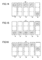
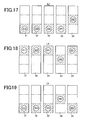
- the RED PLAY 1 LINE button 39 when the RED PLAY 1 LINE button 39 is pressed, the pay line L1 shown in Fig. 11 is activated. And when the PLAY 2 LINES button 40 is pressed, the pay lines L1, L2 shown in Figs. 11 and 12 are activated. And when the PLAY 5 LINES button 41 is pressed, the pay lines L1 ⁇ L5 shown in Figs. 11 to 15 are activated. And when the PLAY 20 LINES button 42 is pressed, the pay lines L1 ⁇ L20 shown in Figs. 11 to 30 are activated. And when the BLACK PLAY 25 LINES button 43 is pressed, the pay lines L1 ⁇ L25 shown in Figs. 11 to 35 are activated.
- each of the RED PLAY 1 LINE button 39, the PLAY 2 LINES button 49, the PLAY 5 LINES button 41, the PLAY 20 LINES button 42 and the BLACK PLAY 25 LINES button 43 is a button to start the game with the present bet number and the number of the activated pay lines and to start variable display of the symbols on each of the variable display portions 21 to 25 in the lower liquid crystal display 4.
- the RED PLAY 1 LINE button 39 and the BLACK PLAY 25 LINES button 43 are also used for selecting red or black in the double down game which is conducted by using the credit obtained in the bonus game.
- the GAMBLE RESERVE button 44 is a button to be pressed when the player leaves the seat and to shift to the double down game after the bonus game is terminated.
- a GAMBLE ⁇ RESERVE switch 48 is attached to the GAMBLE RESERVE button 44 and when the GAMBLE RESERVE button 44 is pressed, a switch signal is output to the CPU 50 from the GAMBLE ⁇ RESERVE switch 48 (see Fig. 4).
- a coin payout opening 15 is formed and a coin tray 16 for receiving coins paid out from the coin payout opening 15 is provided.
- a coin detection portion 73 (mentioned later) which is constructed from sensors and the like (see Fig. 4). And the coin detection portion 73 counts the number of coins paid out from the coin payout opening 15.
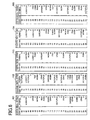
- the symbol row indicated by a first reel strip 101 corresponds to a symbol row variably displayed on the variable display portion 21
- the symbol row indicated by a second reel strip 102 corresponds to a symbol row variably displayed on the display portion 22
- the symbol row indicated by a third reel strip 103 corresponds to a symbol row variably displayed on the variable display portion 23
- the symbol row indicated by a fourth reel strip 104 corresponds to a symbol row variably displayed on the variable display portion 24
- the symbol row indicated by a fifth reel strip 105 corresponds to a symbol row variably displayed on the variable display portion 25.
- the symbol rows respectively indicated by the first to fifth reel strips 101 to 105 have different symbol rows from each other and each symbol row is constructed from 12 symbols by voluntarily combining "LOBSTER”, “SHARK”, “FISH”, “PUNK”, “OCTOPUS”, “CRAB”, “WORM”, “A”, “K”, “Q”, “J” and “SARDINE".
- LOBSTER shows the symbol of lobster as shown in Fig. 7.
- SHARK "FISH”, “PUNK”, “OCTOPUS”, “CRAB”, “WORM”, “SARDINE” are not shown, each symbol shows a shark, a fish, a punk, an octopus, a crab, a worm and a sardine, respectively.
- A”, “K”, “Q” and “J” shows a symbol of English character, respectively.
- SARDINE is a scatter symbol to shift to the bonus game as mentioned later and in a case that more than three "SARDINE" symbols are totally displayed on the variable display portions 21 to 25, the game state can be shifted to the bonus game.
- Fig. 4 is a block diagram schematically showing a control system of the slot machine 1.
- the control system of the slot machine 1 is basically constructed from a CPU 50, and a ROM 51 and a RAM 52 are connected to the CPU 50.
- ROM 51 a main process program mentioned later, a base game process program, a bonus game process program, a lottery table used when it is conducted lottery to determine the symbols which are stopped and displayed in the base game, a lottery table used when it is conducted lottery to determine the symbols which are stopped and displayed in the bonus game, and the other various programs necessary for control of the slot machine 1 and data tables.
- the RAM 52 is a memory to temporarily store various data calculated by the CPU 50.
- a clock pulse generator 53 for generating standard clock pulses and a frequency divider 54 are connected, and a random number generator 55 for generating random numbers and a random number sampling circuit 56 are also connected.
- the random number sampled through the random number sampling circuit 56 is utilized in various lotteries of the winning symbol combinations and the like.
- the COLLECT switch 45 attached to the COLLECT button 31, the GAME ⁇ RULES switch 46 attached to the GAME RULES button 32, the 1-BET switch 57 attached to the BET 1 PER LINE button 33, the 2-BET switch 58 attached to the BET 2 PER LINES button 34, the 3-BET switch 59 attached to the BET 3 PER LINES button 35, the 5-BET switch 60 attached to the BET 5 PER LINES button 36, the 8-BET switch 60 attached to the BET 8 PER LINES button 37, the WIN-START switch 47 attached to the WIN START FEATURE button 38, the 1-LINE switch 62 attached to the RED PLAY 1 LINE button 39, the 2-LINES switch 63 attached to the PLAY 2 LINES button 40, the 5-LINES switch 64 attached to the PLAY 5 LINES button 41, the 20-LINES switch 65 attached to the PLAY 20 LINES button 42, the 25-LINES switch 66 attached to the BLACK PLAY 25
- the coin sensor 49 arranged in the coin insertion slot 9 and the bill sensor 67 arranged in the bill insertion portion 10 are respectively connected.
- the coin sensor 49 detects coins inserted from the coin insertion slot 9 and the CPU 50 calculates the number of inserted coins based on the coin detection signal output from the coin sensor 49.
- the bill sensor 67 detects kinds and sum of the bill inserted from the bill insertion portion 10 and the CPU 50 calculates the credit number equal to the sum of bill, based on the bill detection signal output from the bill sensor 67.
- a hopper 71 is connected to the CPU 50, a hopper 71 is connected through a hopper drive circuit 70.
- a drive signal is output to the hopper drive circuit 70 from the CPU 50, the hopper 71 pays out a predetermined number of coins from the coin payout opening 15.
- a coin detection portion 73 is connected through a payout completion signal circuit 72.
- the coin detection portion 73 is arranged in the coin payout opening 15 and when the coin detection portion 73 detects that a predetermined number of coins are paid out from the coin payout opening 15, a coin payout detection signal is output to the payout completion signal circuit 72 from the coin detection portion 73, thereby the payout completion signal circuit 72 outputs a payout completion signal to the CPU 50.
- the upper liquid crystal display 3 and the lower liquid crystal display 4 are connected through a liquid crystal drive circuit 74, and the upper liquid crystal display 3 and the lower liquid crystal display 4 are controlled by the CPU 50.
- the liquid crystal drive circuit 74 is constructed from a program ROM 81, an image ROM 82, an image control CPU 83, a work RAM 84, a VDP (video display processor) 85 and a video RAM 68.
- the program ROM 81 there are stored an image control program for controlling display of the upper liquid crystal display 3 and the lower liquid crystal display 4 and various selection tables.
- the image ROM 82 for example, there are stored dot data for forming images of the symbol rows indicated by the first to fifth reel strips 101 to 105 in Fig. 6, such images being displayed on the lower liquid crystal display 4 (or variable display portions 21 to 25).
- the image control CPU 83 determines the images displayed on the upper liquid crystal display 3 and the lower liquid crystal display 4 among the dot data stored beforehand in the image ROM 82, according to the image control program stored beforehand in the program ROM 81 based on parameters set by the CPU 50. Further, the work RAM 84 functions as temporary memory when the image control program is executed by the image control CPU 83. And the VDP 85 forms images corresponding to display contents determined by the image control CPU 83 and outputs such images to the upper liquid crystal display 3 and the lower liquid crystal display 4. Thereby, for example, the symbol rows indicated by the first to fifth reel strips 101 to 105 are scrolled and displayed on the lower liquid crystal display 4 (or the variable display portions 21 to 25).
- the video RAM 86 functions as temporary memory when images are formed by the VDP 85.
- LEDs 78 are connected through a LED drive circuit 77.
- Many LEDs 78 are arranged on the front plane of the slot machine 1 and are controlled so as to turn on or turn off by the LED drive circuit 77 based on the drive signal from the CPU 50, when various effects are done.
- a sound output circuit 79 and a speaker 80 are connected to the CPU 50 and the speaker 80 produces various effect sounds when various effects are conducted based on the output signal from the sound output circuit 79.
- a touch panel 121 is connected through a touch panel drive circuit 122.
- the touch panel 121 is arranged on the image plane of the lower liquid crystal display 4 and when the player touches on the variable display portions 21 to 25 by the finger, the touch panel 121 can recognize through the touch panel drive circuit 122 not only the variable display portion on which the player touches among the variable display portions 21 to 25 but also the stop area on which the player touches among the first stop areas 211, 221, 231, 241, 151, the second stop areas 212, 222, 232, 242, 252 and the third stop areas 213, 223, 233, 243, 253.
- the touch panel 121 can recognize through the touch panel drive circuit 122 the variable display portion on which the player touches among the variable display portions 21 to 25, based on coordinate information of the portion which is touched by the player.
- the symbols stopped and displayed on the activated pay line L1 shown in Fig. 11 are determined every each of the variable display portions 21 to 25.
- code Nos. "00" ⁇ "29" are respectively allotted to the symbol in each symbol row indicated by the first to fifth reel strips 101 to 105 as shown in Fig. 6, in order of the upper most symbol.
- the lottery table shown in Fig. 9 is provided beforehand. Further, five random numbers are sampled by the random number sampling circuit 56 so as to correspond to each of the variable display portions 21 to 25.
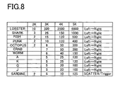
- Fig. 8 is an explanatory view showing the winning symbol combinations and payouts thereof in a case that the base game is done by using five variable display portions 21 to 25, and shows payouts in a case that the bet number is "1". Therefore, if the bet number is "1", the payout number shown in Fig. 8 is added to the credit, and if the bet number is more than "2", the value obtained by multiplying the bet number with the payout number shown in Fig. 8 is added to the credit.
- the payout number "7” can be obtained. Further, if the symbols "CRAB” are stopped and displayed in series along the activated pay line on the variable display portions 21 to 24 (if four symbols “CRAB” appear in series from the left end (this case is called as “4K”)), the payout number "50” can be obtained.
- the payout number calculated by multiplying the payout number shown in Fig. 8 with the total bet number (a product of the bet number and the number of activated pay line) is added to the credit. At that time, if it exists the payout other than the payout on the basis of the symbol "SARDINE", such payout is also added to the credit.
- the bonus game is a game which is conducted after the base game is terminated, and in many cases the bonus game is generally more beneficial for the player. If the game state shifts to the bonus game, 15 - 25 games can be continuously and automatically done without betting any credits corresponding to a result of the lottery conducted when the game state shifts to the bonus game.
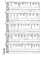
- the symbol row variably displayed while being scrolled on the variable display portion 21 of the lower liquid crystal display 4 is the symbol row indicated by the first reel strip 123 shown in Fig. 46
- the symbol row variably displayed while being scrolled on the variable display portion 22 of the lower liquid crystal display 4 is the symbol row indicated by the second reel strip 124 shown in Fig. 46
- the symbol row variably displayed while being scrolled on the variable display portion 23 of the lower liquid crystal display 4 is the symbol row indicated by the third reel strip 125 shown in Fig. 46
- the symbol row variably displayed while being scrolled on the variable display portion 24 of the lower liquid crystal display 4 is the symbol row indicated by the fourth reel strip 126 shown in Fig. 46
- the symbol row variably displayed while being scrolled on the variable display portion 25 of the lower liquid crystal display 4 is the symbol row indicated by the fifth reel strip 127 shown in Fig. 46.
- the symbol rows indicated by the reel strips 123 to 126 shown in Fig. 46 are as same as those indicated by the reel strips 101 to 104 shown in Fig. 6.
- the symbol row indicated by the reel strip 127 shown in Fig. 46 is substantially as same as the symbol row indicated by the reel strip 105 shown in Fig. 6, except for the symbol "LOBSTER" (shown in Fig. 7) allotted to the code No. "10".
- the bet number and the number of activated pay line in the bonus game the bet number and the number of activated pay line set in the base game are utilized, respectively.
- the symbol "SHARK” is handled as the symbol “LOBSTER” (shown in Fig. 7) and if more than three symbols “SARDINE” totally appear (are totally stopped and displayed), the game state in the bonus game can be again shifted to the bonus game. Therefore, the player can obtain a lot of credits in many cases.
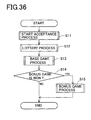
- Fig. 36 is a flowchart of the main process program.
- S step (abbreviated as "S" hereinafter) 11
- a start acceptance process shown in Fig. 37 is done.
- This process is a process for accepting the switch signal output from the 1-BET switch 57, the 2-BET switch 58, the 3-BET switch 59, the 5-BET switch 60, the 8-BET switch 61, the 1-LINE switch 62, the 2-LINES switch 63, the 5-LINES switch 64, the 20-LIENS switch 65, the 25-LINES switch 66, based on operation of the BET 1 PER LINE button 33, the BET 2 PER LINES button 34, the BET 3 PER LINES button 35, the BET 5 PER LINES 36, the BET 8 PER LINES button 37, the RED PLAY 1 LINE button 39, the PLAY 2 LINES button 40, the PLAY 5 LINES button 41, the PLAY 20 LINES button 42 or the BLACK PLAY 25 LINES button 43.
- the switch signal output from each switch is accepted, the game is started.
- a repeat number of the bonus game is determined.
- such repeat number is selected among 10 - 25 games by a lottery.
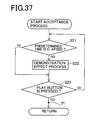
- Fig. 37 is a flowchart of the start acceptance process program.
- S11 of the main process program shown in Fig. 36 the start acceptance process is conducted.
- procedure returns to S21 and the above procedures are repeated.
- procedure returns to the main process program of Fig. 36 and shifts to the lottery process in S12 even while the demonstration effect is done.
- such determination in S23 may be conducted based on the other input signals other than the above operation signals.
- Fig. 38 is a flowchart of the lottery process program.
- S12 of the main process program shown in Fig. 36 the lottery process is done.
- procedure shifts to S31 of Fig. 38 and a symbol determination process is conducted.
- the symbols stopped and displayed on the first pay line L1 in the base game are determined every each of the variable display portions 21 to 25.
- five random number values are sampled by the random number sampling circuit 56 so as to correspond to each of the variable display portions 21 to 25 and the symbols stopped and displayed are determined through the code Nos. based on the lottery table shown in Fig. 9.
- Fig. 39 is a flowchart of the base game process program.
- S13 of the main process program shown in Fig. 36 the base game is conducted.
- Scroll of each of the symbols is done on the variable display portions 21 to 25 based on the switch signal output from the 1-LINE switch 62, the 2-LINES switch 63, the 5-LINES switch 64, the 20-LINES switch 65 or the 25-LINES switch 66, the switch signal being accepted in S11 of Fig. 36.
- Fig. 39 is a flowchart of the bonus game process program.
- S14 of the main process program shown in Fig. 36 if it is determined that the bonus game is won (S14: YES), procedure shifts to S15 of Fig. 36 and the bonus game process is conducted.
- procedure shifts to S39 shown in Fig. 39 and the lottery process during the bonus game is done.
- the symbols stopped and displayed on the first pay line L1 are determined every each of the variable display portions 21 to 25.
- five random number values are sampled by the random number sampling circuit 56 so as to correspond to each of the variable display portions 21 to 25, and the symbols stopped and displayed are determined through the code Nos. based on the lottery table shown in Fig. 9. And if the symbols stopped and displayed on the first pay line L1 are determined, the winning symbol combination and the payout thereof are determined based on the table shown in Fig. 8 through the code Nos.
- the repeat number of times of the bonus game is determined again and the determined repeat number of times is added to the "number of times determined in S12 of Fig. 36" used in the determination process in S55.
- procedure can again shift to the bonus game.
- the bonus games are conducted in 25 times (20 times - 12 times + 17 times) thereafter.
- the CPU 50 functions as "game controller" when the main process program of Fig. 36 is executed.
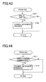
- the process shown in Fig. 43 is conducted at the time point W right after the determination process of S23 in the start acceptance process program in Fig. 37 is done. That is to say, in the start acceptance process program of Fig. 37, if it is determined that the play button is pressed (S23: YES), procedure shifts to S101 in Fig. 43 and it is determined whether or not a bill is inserted in S101. Concretely, this determination is done based on whether or not the bill detection signal is output from the bill sensor 67.
- procedure returns to the start acceptance process program in Fig. 37 and shifts to S12 of the main process program in Fig. 36.
- procedure shifts to S102 and a symbol movement process mentioned later is done, thereafter procedure returns to start acceptance process program in Fig. 37 and shifts to S12 of the main process program in Fig. 36.
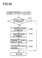
- Fig. 45 is a flowchart of the symbol movement process. That is to say, as shown in Fig. 45, in the symbol movement process, at first, it is determined whether or not the touch panel 121 is touched within the variable display portions 21 to 25 in S121. At that time, if it is determined that the touch panel 121 is not touched within the variable display portions 21 to 25 (S121: NO), procedure returns to the process shown in Fig. 43. On the other hand, if it is determined that the touch panel 121 is touched within the variable display portions 21 to 25 (S 121: YES), procedure shifts to S122.
- the window touched by the finger is specified.
- the window is defined as any of the first stop areas 211, 221, 231, 241, 251, the second stop areas 212, 222, 232, 242, 252 and the third stop areas 213, 223, 233, 243, 253, within the variable display portions 21 to 25. Further, when procedure shifts to S123, the symbol stopped and displayed on the specified window is also specified.
- the display mode of the symbol specified in S123 is changed within the specified window.
- the symbol specified in S123 is the symbol "LOBSTER" (shown in Fig. 7)
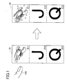
- the image that the lobster springs as shown in Fig. 42 is displayed.
- procedure shifts to S125 the effect sounds corresponding to change of the display mode in S124 are output, thereafter procedure returns to the process in Fig. 43.
- the concrete effect sounds for example, if the symbol specified in S123 is the symbol "LOBSTER" (shown in Fig. 7), the effect sounds such as sprightly sounds representing springing lobster as shown in Fig. 42 are output.
- the images that the display mode of the symbol is changed are stored in the image ROM 82, every each of the symbol “LOBSTER”, the symbol “SHARK”, the symbol “FISH”, the symbol “PUNK”, the symbol “OCTOPUS”, the symbol “CRAB”, the symbol “WORM”, the symbol “SARDINE”, the symbol “A”, the symbol “K”, the symbol “Q” and the symbol “J”.
- the symbol specified in S123 is read out and output in the window specified in S122.
- the effect sounds when the display mode of the symbol is changed are stored in the ROM 51, every each of the symbol “LOBSTER”, the symbol “SHARK”, the symbol “FISH”, the symbol “PUNK”, the symbol “OCTOPUS”, the symbol “CRAB”, the symbol “WORM”, the symbol “SARDINE”, the symbol “A”, the symbol “K”, the symbol “Q” and the symbol “J”. And the effect sounds of the symbol specified in S123 are read out and output from the speaker 80.
- the CPU 50 functions as "first permission device” when the process program in Fig. 43 is executed. And the CPU 50 functions as "symbol movement device” when the symbol movement process program in Fig. 45 is executed.
- the symbol can be moved and the effect sounds can be output based on that the symbol stopped and displayed on each of the variable display portions 21 to 25 is touched by the finger.
- the process shown in Fig. 44 is conducted at the time point W2 right after the stop control process of S42 in the base game process program in Fig. 39 is done. That is to say, in the base game process program shown in Fig. 39, if the stop control process in S42 is executed, procedure shifts to S111 in Fig. 44 and it is determined whether or not the symbol combination stopped and displayed on each of the variable display portions 21 to 25 is the predetermined symbol combination. At that time, if it is determined that the symbol combination stopped and displayed on each of the variable display portions 21 to 25 is not the predetermined symbol combination (S111: NO), procedure shifts to S43 of the base game process program in Fig. 39.
- the CPU 50 functions as "second permission device".
- the symbol combination stopped and displayed on each of the variable display portions 21 to 25 is the symbol combination corresponding to the winning symbol combination shown in Fig. 8.
- the object to be determined in S111 may be limited to the symbol combination stopped and displayed on the pay line which is activated among the pay lines L1 ⁇ L25.
- the display mode thereof may be changed and the effect sounds may be output.
- the slot machine 1 at the time that the game state shifts from one base game to another base game, when a bill is inserted in the bill insertion portion 10 in a case that, for example as shown in Fig. 1, the symbol “LOBSTER” is stopped and displayed on the first stop area 211, the symbol “J” is stopped and displayed on the second stop area 212 and the symbol “Q” is stopped and displayed on the third stop area 213, within the variable display portion 21, the symbol “LOBSTER” displayed on the first stop area 211 is displayed so as to spring and the effect sounds representing springing lobster are output when the player touches on the first stop area 211 by the finger 128.
- the above point that the display mode of the symbol can be changed is not limited to the first stop area 211 in the variable display portion 21 and can be realized on the second stop area 212 or the third stop area 213 in the variable display portion 21. Further, similarly, the above point can be also realized on the first stop areas 221, 231, 241, 251, the second sop and display areas 222, 232, 242, 252 and the third atop and display areas 223, 233, 243, 253.
- the above point can be similarly realized in a case that the symbol combination stopped and displayed on each of the variable display portions 21 to 25 is the predetermined symbol combination (for example, the symbol combination corresponding to the winning symbol combination shown in Fig. 8).
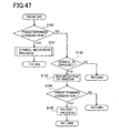
- the gaming machine of the present invention may run the following processes shown in Fig. 47 alternatively to the steps described in Fig. 44.
- the symbol "LOBSTER" is used as a wild symbol.
- the CPU 50 determines in S133 to which window the symbol "LOBSTER” has been dragged on. Namely, the window to which the symbol "LOBSTER” has been dragged on is specified in S133. Thereafter, the CPU 50 determines in S134 whether thus dragged symbol "LOBSTER” forms a predetermined combination that results in award. That is, it is determined in S134 whether or not the winning symbol combination is formed based on that the symbol "LOBSTER” is dragged onto the stop area. If determined “NO” in S134, procedure shifts to the main process program shown in Fig. 36.
- the above mentioned dragging process may be combined with the symbol movement process described in Fig. 44. Namely, after determined as "YES” in S111 of Fig. 44, the gaming machine of the present invention may require the player to drag the symbol "LOBSTER” to a desirable stop area so as to obtain additional awards. Thereafter the CPU 50 may run the symbol movement process so that the player can see that the symbol "LOBSTER" has resulted in the additional awards.
- the dragging may be carried out in bonus game like free game.
- the present invention is not limited to the video slot machine, and for example, when the player touches the symbol stopped and displayed on the lower liquid crystal display 4 by the finger 128 in the game (for example, the poker game in which trump symbols are used) that is executed by using symbols displayed on the lower liquid crystal display 4, the symbol may be moved and the effect sounds may be output.
- the game for example, the poker game in which trump symbols are used
- the symbol stopped and displayed on the first pay line L1 is determined every each of the variable display portions 21 to 25 in the base game and the bonus game, based on the lottery table in Fig. 9 in which one random number value sampled through the random number sampling circuit 56 and one code No. are corresponded with each other.
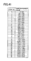
- the symbol stopped and displayed on the first pay line L1 may be determined every each of the variable display portions 21 to 25, based on the lottery table in Fig. 41 in which a specific range of the random numbers sampled through the random number sampling circuit 56 corresponds to one code No..
- the present invention can be applied when the game is executed by using symbols displayed on the display device.
Landscapes
- Physics & Mathematics (AREA)
- General Physics & Mathematics (AREA)
- Slot Machines And Peripheral Devices (AREA)
- Display Devices Of Pinball Game Machines (AREA)
- Pinball Game Machines (AREA)
Applications Claiming Priority (2)
| Application Number | Priority Date | Filing Date | Title |
|---|---|---|---|
| JP2004127154 | 2004-04-22 | ||
| JP2004127154A JP2005304855A (ja) | 2004-04-22 | 2004-04-22 | 遊技機 |
Publications (1)
| Publication Number | Publication Date |
|---|---|
| EP1589504A1 true EP1589504A1 (de) | 2005-10-26 |
Family
ID=34935521
Family Applications (1)
| Application Number | Title | Priority Date | Filing Date |
|---|---|---|---|
| EP05008748A Withdrawn EP1589504A1 (de) | 2004-04-22 | 2005-04-21 | Spielautomat |
Country Status (7)
| Country | Link |
|---|---|
| US (1) | US20050239532A1 (de) |
| EP (1) | EP1589504A1 (de) |
| JP (1) | JP2005304855A (de) |
| CN (1) | CN100531835C (de) |
| AU (1) | AU2005201686A1 (de) |
| EA (1) | EA008530B1 (de) |
| ZA (1) | ZA200503226B (de) |
Families Citing this family (30)
| Publication number | Priority date | Publication date | Assignee | Title |
|---|---|---|---|---|
| US8277303B2 (en) * | 2003-03-27 | 2012-10-02 | Labtronix Concept | Method of operating and displaying a meter feature using evolving symbols in a line game |
| JP2005312545A (ja) * | 2004-04-27 | 2005-11-10 | Aruze Corp | 遊技機 |
| JP2005312546A (ja) * | 2004-04-27 | 2005-11-10 | Aruze Corp | 遊技機 |
| JP5791858B2 (ja) * | 2006-04-04 | 2015-10-07 | 株式会社三共 | スロットマシン |
| JP2008092983A (ja) * | 2006-10-06 | 2008-04-24 | Aruze Corp | 遊技機 |
| US7922574B2 (en) | 2006-10-18 | 2011-04-12 | Aruze Gaming America, Inc. | Slot machine and playing method thereof |
| CN101069778B (zh) * | 2007-03-29 | 2010-04-07 | 腾讯科技(深圳)有限公司 | 一种电脑游戏的控制方法及系统 |
| US8633915B2 (en) | 2007-10-04 | 2014-01-21 | Apple Inc. | Single-layer touch-sensitive display |
| AU2008255148A1 (en) | 2007-12-10 | 2009-06-25 | Aristocrat Technologies Australia Pty Limited | A Gaming System and Method of Gaming |
| AU2008255201A1 (en) * | 2007-12-14 | 2009-07-02 | Aristocrat Technologies Australia Pty Limited | Method of gaming, a game controller and a gaming system |
| US20090174676A1 (en) | 2008-01-04 | 2009-07-09 | Apple Inc. | Motion component dominance factors for motion locking of touch sensor data |
| US8760412B2 (en) * | 2009-02-02 | 2014-06-24 | Apple Inc. | Dual configuration for display data lines |
| US8922521B2 (en) | 2009-02-02 | 2014-12-30 | Apple Inc. | Switching circuitry for touch sensitive display |
| US8593410B2 (en) | 2009-04-10 | 2013-11-26 | Apple Inc. | Touch sensor panel design |
| US8957874B2 (en) | 2009-06-29 | 2015-02-17 | Apple Inc. | Touch sensor panel design |
| US20130104039A1 (en) * | 2011-10-21 | 2013-04-25 | Sony Ericsson Mobile Communications Ab | System and Method for Operating a User Interface on an Electronic Device |
| US9329723B2 (en) | 2012-04-16 | 2016-05-03 | Apple Inc. | Reconstruction of original touch image from differential touch image |
| US9886141B2 (en) | 2013-08-16 | 2018-02-06 | Apple Inc. | Mutual and self capacitance touch measurements in touch panel |
| WO2015178920A1 (en) | 2014-05-22 | 2015-11-26 | Onamp Research Llc | Panel bootstrapping architectures for in-cell self-capacitance |
| US10289251B2 (en) | 2014-06-27 | 2019-05-14 | Apple Inc. | Reducing floating ground effects in pixelated self-capacitance touch screens |
| US9880655B2 (en) | 2014-09-02 | 2018-01-30 | Apple Inc. | Method of disambiguating water from a finger touch on a touch sensor panel |
| CN107077260B (zh) | 2014-09-22 | 2020-05-12 | 苹果公司 | 触摸控制器和用于触摸传感器面板的方法 |
| US10712867B2 (en) | 2014-10-27 | 2020-07-14 | Apple Inc. | Pixelated self-capacitance water rejection |
| AU2016215616B2 (en) | 2015-02-02 | 2018-12-06 | Apple Inc. | Flexible self-capacitance and mutual capacitance touch sensing system architecture |
| US10488992B2 (en) | 2015-03-10 | 2019-11-26 | Apple Inc. | Multi-chip touch architecture for scalability |
| US10365773B2 (en) | 2015-09-30 | 2019-07-30 | Apple Inc. | Flexible scan plan using coarse mutual capacitance and fully-guarded measurements |
| AU2017208277B2 (en) | 2016-09-06 | 2018-12-20 | Apple Inc. | Back of cover touch sensors |
| US10642418B2 (en) | 2017-04-20 | 2020-05-05 | Apple Inc. | Finger tracking in wet environment |
| JP7248910B2 (ja) * | 2020-04-02 | 2023-03-30 | 株式会社エンターライズ | 遊技機 |
| US11662867B1 (en) | 2020-05-30 | 2023-05-30 | Apple Inc. | Hover detection on a touch sensor panel |
Citations (3)
| Publication number | Priority date | Publication date | Assignee | Title |
|---|---|---|---|---|
| US20020045482A1 (en) * | 2000-06-29 | 2002-04-18 | Poole Richard W. | Gaming device with multi-purpose reels |
| US20030064800A1 (en) * | 2001-09-28 | 2003-04-03 | Jackson James P. | Video gaming machine with pop-up windows |
| EP1473681A2 (de) * | 2003-05-01 | 2004-11-03 | WMS Gaming Inc | Spielautomat mit interaktiven eingeblendeten Fenstern |
Family Cites Families (4)
| Publication number | Priority date | Publication date | Assignee | Title |
|---|---|---|---|---|
| US6227971B1 (en) * | 1999-09-14 | 2001-05-08 | Casino Data Systems | Multi-line, multi-reel gaming device |
| US6517432B1 (en) * | 2000-03-21 | 2003-02-11 | Wms Gaming Inc. | Gaming machine with moving symbols on symbol array |
| DE10026366B4 (de) * | 2000-04-08 | 2006-07-13 | Nsm-Löwen Entertainment Gmbh | Verfahren zum Betreiben eines geldbetätigten Unterhaltungsgerätes |
| US6347996B1 (en) * | 2000-09-12 | 2002-02-19 | Wms Gaming Inc. | Gaming machine with concealed image bonus feature |
-
2004
- 2004-04-22 JP JP2004127154A patent/JP2005304855A/ja active Pending
-
2005
- 2005-04-20 CN CNB2005100672688A patent/CN100531835C/zh not_active Expired - Fee Related
- 2005-04-20 AU AU2005201686A patent/AU2005201686A1/en not_active Abandoned
- 2005-04-21 ZA ZA200503226A patent/ZA200503226B/en unknown
- 2005-04-21 US US11/110,818 patent/US20050239532A1/en not_active Abandoned
- 2005-04-21 EP EP05008748A patent/EP1589504A1/de not_active Withdrawn
- 2005-04-21 EA EA200500522A patent/EA008530B1/ru not_active IP Right Cessation
Patent Citations (3)
| Publication number | Priority date | Publication date | Assignee | Title |
|---|---|---|---|---|
| US20020045482A1 (en) * | 2000-06-29 | 2002-04-18 | Poole Richard W. | Gaming device with multi-purpose reels |
| US20030064800A1 (en) * | 2001-09-28 | 2003-04-03 | Jackson James P. | Video gaming machine with pop-up windows |
| EP1473681A2 (de) * | 2003-05-01 | 2004-11-03 | WMS Gaming Inc | Spielautomat mit interaktiven eingeblendeten Fenstern |
Also Published As
| Publication number | Publication date |
|---|---|
| JP2005304855A (ja) | 2005-11-04 |
| CN100531835C (zh) | 2009-08-26 |
| ZA200503226B (en) | 2006-02-22 |
| US20050239532A1 (en) | 2005-10-27 |
| EA008530B1 (ru) | 2007-06-29 |
| CN1689677A (zh) | 2005-11-02 |
| EA200500522A3 (ru) | 2006-02-24 |
| EA200500522A2 (ru) | 2005-12-29 |
| AU2005201686A1 (en) | 2005-11-10 |
Similar Documents
| Publication | Publication Date | Title |
|---|---|---|
| EP1589504A1 (de) | Spielautomat | |
| EP1589505A1 (de) | Spielautomat | |
| AU2005209676B2 (en) | Gaming machine | |
| US8328627B2 (en) | Gaming machine with player predictable volatility | |
| US8998699B2 (en) | Slot machine | |
| US20110151960A1 (en) | Gaming machine with multi scatter game | |
| US20090275387A1 (en) | Solt Machine | |
| ZA200208712B (en) | Gaming machine with win change symbol. | |
| US20090104971A1 (en) | Slot Machine | |
| EP1594096A2 (de) | Spielgerät | |
| US20060046831A1 (en) | Gaming machine | |
| EP1662449A2 (de) | Spielautomat | |
| EP1591974A1 (de) | Spielautomat | |
| EP1622103A1 (de) | Spielgerät | |
| US20080146316A1 (en) | Gaming machine with bonus game | |
| US20060287061A1 (en) | Gaming machine | |
| US20060068891A1 (en) | Gaming machine | |
| US20070155479A1 (en) | Gaming machine | |
| US20090275388A1 (en) | Slot Machine | |
| US20060247025A1 (en) | Gaming machine | |
| US20070178960A1 (en) | Gaming machine | |
| US20080146315A1 (en) | Gaming machine with bonus game |
Legal Events
| Date | Code | Title | Description |
|---|---|---|---|
| PUAI | Public reference made under article 153(3) epc to a published international application that has entered the european phase |
Free format text: ORIGINAL CODE: 0009012 |
|
| AK | Designated contracting states |
Kind code of ref document: A1 Designated state(s): AT BE BG CH CY CZ DE DK EE ES FI FR GB GR HU IE IS IT LI LT LU MC NL PL PT RO SE SI SK TR |
|
| AX | Request for extension of the european patent |
Extension state: AL BA HR LV MK YU |
|
| 17P | Request for examination filed |
Effective date: 20060327 |
|
| AKX | Designation fees paid |
Designated state(s): AT BE BG CH CY CZ DE DK EE ES FI FR GB GR HU IE IS IT LI LT LU MC NL PL PT RO SE SI SK TR |
|
| STAA | Information on the status of an ep patent application or granted ep patent |
Free format text: STATUS: THE APPLICATION IS DEEMED TO BE WITHDRAWN |
|
| 18D | Application deemed to be withdrawn |
Effective date: 20081125 |