EP1589652A1 - Méthode de commande d'un moteur à courant continu sans balai - Google Patents
Méthode de commande d'un moteur à courant continu sans balai Download PDFInfo
- Publication number
- EP1589652A1 EP1589652A1 EP05007611A EP05007611A EP1589652A1 EP 1589652 A1 EP1589652 A1 EP 1589652A1 EP 05007611 A EP05007611 A EP 05007611A EP 05007611 A EP05007611 A EP 05007611A EP 1589652 A1 EP1589652 A1 EP 1589652A1
- Authority
- EP
- European Patent Office
- Prior art keywords
- motor
- speed
- nominal
- supply voltage
- electric motor
- Prior art date
- Legal status (The legal status is an assumption and is not a legal conclusion. Google has not performed a legal analysis and makes no representation as to the accuracy of the status listed.)
- Withdrawn
Links
- 238000000034 method Methods 0.000 title claims abstract description 7
- 238000004804 winding Methods 0.000 claims abstract description 9
- 230000001276 controlling effect Effects 0.000 abstract 1
- 230000001105 regulatory effect Effects 0.000 abstract 1
- 230000007423 decrease Effects 0.000 description 3
- 238000005265 energy consumption Methods 0.000 description 2
- 230000003247 decreasing effect Effects 0.000 description 1
- 230000001419 dependent effect Effects 0.000 description 1
- 230000007613 environmental effect Effects 0.000 description 1
- 238000010438 heat treatment Methods 0.000 description 1
- 239000004065 semiconductor Substances 0.000 description 1
- 230000003068 static effect Effects 0.000 description 1
Images

Classifications
-
- H—ELECTRICITY
- H02—GENERATION; CONVERSION OR DISTRIBUTION OF ELECTRIC POWER
- H02P—CONTROL OR REGULATION OF ELECTRIC MOTORS, ELECTRIC GENERATORS OR DYNAMO-ELECTRIC CONVERTERS; CONTROLLING TRANSFORMERS, REACTORS OR CHOKE COILS
- H02P6/00—Arrangements for controlling synchronous motors or other dynamo-electric motors using electronic commutation dependent on the rotor position; Electronic commutators therefor
- H02P6/34—Modelling or simulation for control purposes
Definitions
- the invention relates to a method for controlling a brushless Electric motor according to the preamble of patent claim 1.
- Brushless DC motors for fan applications operate with or without a closed-loop control.
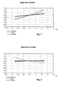
- the speed of a brushless DC motor without speed control is dependent on the supply voltage (see Figure 1).
- the higher the supply voltage the higher the speed of the motor.
- fan motors are used with a nominal supply voltage of 12V.
- the on-board voltage of the vehicles can vary in a range of 8 V to 18 V, so that the speed of the engine can fluctuate considerably.
- the mechanical power output increases approximately at the third power of the speed.
- the speed of the uncontrolled motor increases.
- the engine load increases and therefore can easily occur at too high a supply voltage thermal overloading of the motor.
- the fan provides more air, but the User is not normally needed, because the fan is designed so that He in the entire supply voltage range, a sufficient amount of air supplies.
- the load increases with higher speed engine and noise of the fan. The higher load not only means higher energy consumption, but also one higher self-heating of the engine, which in turn increases the life of the engine Storage system negatively affected.
- the object of the invention is to provide a method for controlling a brushless electric motor to propose in which neither at reduced even at elevated operating voltage increased load on Engine components is created.
- a brushless motor according to the invention is in Claim 3 specified.
- a pulse width modulation (PWM) is preferably used.
- PWM pulse width modulation
- based engine control uses that with a speed control works and is dimensioned so that the motor its nominal nominal Speed at nominal load at nominal supply voltage just reached. In this case, the supply voltage rises above the nominal value, the control prevents an increase in the speed.
- Figure 1 is a representation of the relative speed, the motor current and the Recording power of a brushless fan drive without speed control (Prior art), depending on the relative supply voltage.
- Figure 2 is a representation of the relative speed, the motor current and the Recording power of a brushless fan drive with speed control (Prior art), depending on the relative supply voltage.
- Figure 3 is an illustration of the relative speed, the motor current and the Recording power of a brushless fan drive with speed control according to the invention as a function of the relative supply voltage.
- FIG. 4 shows by way of example the course of the PWM control signal at a Supply voltage, which is significantly higher than the nominal Supply voltage of the fan drive.
- FIG. 5 shows an example of the course of the PWM control signal at nominal Supply voltage.
- the rotational speed is a solid line, the current as close dash line and the performance as a wide dotted line over the tension shown. It was each at rated speed, rated current and rated power and normalized to nominal voltage.
- Figure 2 shows a representation of relative speed, motor current and Recording power of a brushless fan drive with speed control according to the prior art, depending on the relative Supply voltage. Also at supply voltages, by the Nominal voltage differ, remain speed and recording power due to the speed limitation constant.
- FIG. 3 shows the characteristics of a fan drive according to the invention.
- a motor control is used, the Motor current via pulse width modulation (PWM) controls and the speed limits a fixed maximum speed.
- PWM pulse width modulation
- the important thing is that the engine or the motor control is dimensioned so that the nominal Speed at nominal load at nominal supply voltage is reached, with the maximum duty cycle is almost reached.
- Figure 4 shows schematically the PWM control signal at a Supply voltage well above the nominal Supply voltage.
- the speed controller increases this PWM ratio.
- FIG. 5 schematically shows the PWM control signal at a slightly greater supply voltage than the nominal supply voltage. If the supply voltage continues to drop, the duty cycle can no longer or hardly be increased.
- the inventive dimensioning can be realized in many cases with a corresponding winding design. That is, the magnetic circuit and the commutation electronics do not need to be changed.
- One possible way of designing the winding design according to the invention is as follows:
Landscapes
- Engineering & Computer Science (AREA)
- Power Engineering (AREA)
- Control Of Motors That Do Not Use Commutators (AREA)
Applications Claiming Priority (2)
| Application Number | Priority Date | Filing Date | Title |
|---|---|---|---|
| DE102004019004 | 2004-04-20 | ||
| DE102004019004A DE102004019004A1 (de) | 2004-04-20 | 2004-04-20 | Verfahren zur Ansteuerung eines bürstenlosen Elektromotors |
Publications (1)
| Publication Number | Publication Date |
|---|---|
| EP1589652A1 true EP1589652A1 (fr) | 2005-10-26 |
Family
ID=34934844
Family Applications (1)
| Application Number | Title | Priority Date | Filing Date |
|---|---|---|---|
| EP05007611A Withdrawn EP1589652A1 (fr) | 2004-04-20 | 2005-04-07 | Méthode de commande d'un moteur à courant continu sans balai |
Country Status (4)
| Country | Link |
|---|---|
| US (1) | US7095189B2 (fr) |
| EP (1) | EP1589652A1 (fr) |
| JP (1) | JP2005312292A (fr) |
| DE (1) | DE102004019004A1 (fr) |
Cited By (2)
| Publication number | Priority date | Publication date | Assignee | Title |
|---|---|---|---|---|
| WO2008095565A1 (fr) * | 2007-02-05 | 2008-08-14 | Robert Bosch Gmbh | Dispositif de ventilation ayant une disponibilité élevée et son procédé de fonctionnement |
| RU2366069C1 (ru) * | 2007-12-24 | 2009-08-27 | Общество с ограниченной ответственностью "Научно-исследовательский институт механотронных технологий-Альфа-Научный Центр" (ООО "НИИМЕХАНОТРОНИКИ-АЛЬФА-НЦ") | Вентильный электропривод |
Families Citing this family (6)
| Publication number | Priority date | Publication date | Assignee | Title |
|---|---|---|---|---|
| US20070205731A1 (en) * | 2006-03-01 | 2007-09-06 | Regal-Beloit Corporation | Methods and systems for dynamically braking an electronically commutated motor |
| JP4687730B2 (ja) * | 2008-03-06 | 2011-05-25 | パナソニック株式会社 | 送風装置およびそれを搭載した電気機器 |
| DE102009041878A1 (de) * | 2009-09-07 | 2011-03-10 | C. & E. Fein Gmbh | Steuerbarer Gleichstrom-Motor mit modifizierter Kennlinie |
| US9735720B2 (en) * | 2012-09-07 | 2017-08-15 | Ford Global Technologies, Llc | Electric motor torque control |
| DE102012220223A1 (de) * | 2012-11-07 | 2014-05-08 | Robert Bosch Gmbh | Elektrowerkzeug und Verfahren zu seinem Betrieb |
| RU2658678C1 (ru) * | 2017-05-25 | 2018-06-22 | Зао "Нии Механотроники-Альфа-Нц" | Бесконтактный электропривод постоянного тока |
Citations (4)
| Publication number | Priority date | Publication date | Assignee | Title |
|---|---|---|---|---|
| US5563980A (en) * | 1994-12-14 | 1996-10-08 | Industrial Technology Research Institute | Brushless DC motor speed controller |
| EP0802613A2 (fr) * | 1996-04-16 | 1997-10-22 | PM DM Precision Motors Deutsche Minebea GmbH | Moteur à courant continu sans balai, multiphase |
| EP0899862A2 (fr) * | 1997-08-28 | 1999-03-03 | Barber Colman | Système et méthode de réponse en cas de panne de secteur pour un actionneur |
| EP1383232A2 (fr) * | 2002-07-16 | 2004-01-21 | Robert Bosch Gmbh | Méthode d'amélioration de la disponibilité d'un système de ventilateur |
Family Cites Families (17)
| Publication number | Priority date | Publication date | Assignee | Title |
|---|---|---|---|---|
| US3870860A (en) * | 1973-03-15 | 1975-03-11 | Emerson Electric Co | Floor drop-in forced circulation electric space heater |
| US5075608A (en) * | 1974-06-24 | 1991-12-24 | Erdman David M | Control system, electronically commutated motor system, draft inducer apparatus and method |
| US4843532A (en) * | 1988-07-01 | 1989-06-27 | General Electric Company | Regulating pulse width modulator for power supply with high speed shutoff |
| JPH06165571A (ja) * | 1992-11-18 | 1994-06-10 | Matsushita Electric Ind Co Ltd | ブラシレスモータの制御装置 |
| DE19647983A1 (de) * | 1995-12-04 | 1997-06-05 | Papst Motoren Gmbh & Co Kg | Verfahren zum Regeln einer physikalischen Größe und Anordnung zur Durchführung eines solchen Verfahrens |
| US6040668A (en) * | 1996-11-14 | 2000-03-21 | Telcom Semiconductor, Inc. | Monolithic fan controller |
| US5963706A (en) * | 1997-10-23 | 1999-10-05 | Baik; Edward Hyeen | Control system for multi-phase brushless DC motor |
| JPH11334630A (ja) * | 1998-05-22 | 1999-12-07 | Koyo Seiko Co Ltd | パワーステアリング装置 |
| JPH11341877A (ja) * | 1998-05-22 | 1999-12-10 | Tamiya Inc | 電動モータ速度制御装置 |
| EP1219011B1 (fr) * | 1999-09-15 | 2003-05-07 | Robert Bosch Gmbh | Moteur a commutation electronique |
| DE10044742A1 (de) * | 1999-09-15 | 2001-04-19 | Bosch Gmbh Robert | Elektronisch kommutierbarer Motor |
| US6426602B1 (en) * | 1999-09-16 | 2002-07-30 | Delphi Technologies, Inc. | Minimization of motor torque ripple due to unbalanced conditions |
| WO2002019511A1 (fr) * | 2000-08-30 | 2002-03-07 | Papst-Motoren Gmbh & Co. Kg | Systeme de ventilation |
| KR100434236B1 (ko) * | 2001-10-11 | 2004-06-04 | 페어차일드코리아반도체 주식회사 | 모터 제어 구동 회로 |
| US6762636B1 (en) * | 2001-12-11 | 2004-07-13 | Cypress Semiconductor Corp. | Circuit and method for adjusting duty cycle of a high speed, low swing output signal |
| US6650074B1 (en) * | 2002-05-29 | 2003-11-18 | Dell Products, L.P. | Fan speed controller with conditioned tachometer signal |
| US7692399B2 (en) * | 2003-04-01 | 2010-04-06 | Hewlett-Packard Development Company, L.P. | DC motor control |
-
2004
- 2004-04-20 DE DE102004019004A patent/DE102004019004A1/de not_active Withdrawn
-
2005
- 2005-04-07 EP EP05007611A patent/EP1589652A1/fr not_active Withdrawn
- 2005-04-11 US US11/103,295 patent/US7095189B2/en not_active Expired - Lifetime
- 2005-04-13 JP JP2005115515A patent/JP2005312292A/ja not_active Withdrawn
Patent Citations (4)
| Publication number | Priority date | Publication date | Assignee | Title |
|---|---|---|---|---|
| US5563980A (en) * | 1994-12-14 | 1996-10-08 | Industrial Technology Research Institute | Brushless DC motor speed controller |
| EP0802613A2 (fr) * | 1996-04-16 | 1997-10-22 | PM DM Precision Motors Deutsche Minebea GmbH | Moteur à courant continu sans balai, multiphase |
| EP0899862A2 (fr) * | 1997-08-28 | 1999-03-03 | Barber Colman | Système et méthode de réponse en cas de panne de secteur pour un actionneur |
| EP1383232A2 (fr) * | 2002-07-16 | 2004-01-21 | Robert Bosch Gmbh | Méthode d'amélioration de la disponibilité d'un système de ventilateur |
Cited By (3)
| Publication number | Priority date | Publication date | Assignee | Title |
|---|---|---|---|---|
| WO2008095565A1 (fr) * | 2007-02-05 | 2008-08-14 | Robert Bosch Gmbh | Dispositif de ventilation ayant une disponibilité élevée et son procédé de fonctionnement |
| US8628310B2 (en) | 2007-02-05 | 2014-01-14 | Robert Bosch Gmbh | Fan system having improved availability and method for its operation |
| RU2366069C1 (ru) * | 2007-12-24 | 2009-08-27 | Общество с ограниченной ответственностью "Научно-исследовательский институт механотронных технологий-Альфа-Научный Центр" (ООО "НИИМЕХАНОТРОНИКИ-АЛЬФА-НЦ") | Вентильный электропривод |
Also Published As
| Publication number | Publication date |
|---|---|
| DE102004019004A1 (de) | 2005-11-24 |
| US20050231139A1 (en) | 2005-10-20 |
| JP2005312292A (ja) | 2005-11-04 |
| US7095189B2 (en) | 2006-08-22 |
Similar Documents
| Publication | Publication Date | Title |
|---|---|---|
| DE102015003195B4 (de) | Elektropumpe | |
| EP2476202B1 (fr) | Moteur à courant continu commandable à courbe caractéristique modifiée | |
| DE10158994A1 (de) | Motortyp mit variabler Spulenwicklungszahl und Verfahren zur Veränderung der Spulenwicklungsanzahl zum Regeln einer Kühl- und Heizkapazität eines Kolbenverdichters | |
| DE10231452A1 (de) | Lüftersteuerungssystem unter Verwendung einer Mikrosteuerung | |
| DE102013003512B4 (de) | Spannungsversorgung in einem Bordnetz für einen Verdichter einer Luftversorgungsanlage | |
| EP1683259B1 (fr) | Moteur a commutation electronique, et procede pour le commander | |
| EP1589652A1 (fr) | Méthode de commande d'un moteur à courant continu sans balai | |
| EP1830370A2 (fr) | Dispositif destiné à la commande d'un mécanisme de commande électromagnétique | |
| EP3257134B1 (fr) | Procédé de fonctionnement d'un convertisseur actif connecté à une machine électrique et dispositif pour sa mise en oeuvre | |
| DE102011088976A1 (de) | Anordnung zur Ansteuerung einer elektrischen Vakuum-Pumpe | |
| EP1107440B1 (fr) | Méthode et circuit pour mise en circuit d'un étage de puissance | |
| WO2008086909A1 (fr) | Procédé de réglage d'un débit volumique | |
| DE102008011224A1 (de) | Generatorvorrichtung mit Überspannungsüberwachung | |
| DE202008006853U1 (de) | Elektronisch kommutierter Gleichstrommotor mit einem pi-Filter | |
| EP2680432B1 (fr) | Procédé destiné à la commande d'un moteur pas à pas | |
| EP1473824A2 (fr) | Unité de commande pour commander un transistor de contrôle d'un ventilateur | |
| DE102009056802B4 (de) | Ansteuerelektronik für ein elektromagnetisch betätigtes Ventil zum Betrieb einer hydrostatischen Verdrängereinheit | |
| DE102010018777A1 (de) | Energieversorgungssystem für einen elektrischen Verbraucher in einem Kraftfahrzeug | |
| DE102013200248A1 (de) | Verfahren und Vorrichtung zum Auslegen eines Elektromotorsfür eine oder mehrere Anwendungen | |
| EP1322024A2 (fr) | Adaptation de niveau de puissance auto-pilotée | |
| EP1228563A1 (fr) | Moteur a commutation electronique | |
| DE102013206445A1 (de) | Verfahren zum Betrieb eines Niederdruck-Kraftstofffördersystems und ein Niederdruck-Kraftstofffördersystem | |
| WO2013045148A2 (fr) | Procédé de fonctionnement d'un moteur électrique à commutation électronique | |
| DE102008018012B3 (de) | Schaltungsanordnung zum Betreiben einer kapazitiven Last sowie Verwendung einer derartigen Schaltungsanordnung | |
| EP2161426A2 (fr) | Procédé de limitation de la puissance d'un moteur électrique fonctionnant sur un réseau de courant continu, notamment pour un ventilateur dans un véhicule automobile, ainsi que dispositif d'exécution du procédé |
Legal Events
| Date | Code | Title | Description |
|---|---|---|---|
| PUAI | Public reference made under article 153(3) epc to a published international application that has entered the european phase |
Free format text: ORIGINAL CODE: 0009012 |
|
| AK | Designated contracting states |
Kind code of ref document: A1 Designated state(s): AT BE BG CH CY CZ DE DK EE ES FI FR GB GR HU IE IS IT LI LT LU MC NL PL PT RO SE SI SK TR |
|
| AX | Request for extension of the european patent |
Extension state: AL BA HR LV MK YU |
|
| 17P | Request for examination filed |
Effective date: 20051112 |
|
| AKX | Designation fees paid |
Designated state(s): DE FI IT |
|
| STAA | Information on the status of an ep patent application or granted ep patent |
Free format text: STATUS: THE APPLICATION IS DEEMED TO BE WITHDRAWN |
|
| 18D | Application deemed to be withdrawn |
Effective date: 20100220 |