EP1590165B1 - Annietmutter und einbauverfahren - Google Patents
Annietmutter und einbauverfahren Download PDFInfo
- Publication number
- EP1590165B1 EP1590165B1 EP03811987A EP03811987A EP1590165B1 EP 1590165 B1 EP1590165 B1 EP 1590165B1 EP 03811987 A EP03811987 A EP 03811987A EP 03811987 A EP03811987 A EP 03811987A EP 1590165 B1 EP1590165 B1 EP 1590165B1
- Authority
- EP
- European Patent Office
- Prior art keywords
- insert
- set forth
- hole
- indenter
- nut
- Prior art date
- Legal status (The legal status is an assumption and is not a legal conclusion. Google has not performed a legal analysis and makes no representation as to the accuracy of the status listed.)
- Expired - Lifetime
Links
- 238000000034 method Methods 0.000 title claims abstract description 127
- 238000009434 installation Methods 0.000 title claims abstract description 47
- 229910052751 metal Inorganic materials 0.000 claims abstract description 105
- 239000002184 metal Substances 0.000 claims abstract description 105
- 238000007373 indentation Methods 0.000 claims description 37
- 230000014759 maintenance of location Effects 0.000 claims description 33
- 230000002093 peripheral effect Effects 0.000 claims description 25
- 239000007787 solid Substances 0.000 claims description 25
- 230000002441 reversible effect Effects 0.000 claims description 23
- 230000000295 complement effect Effects 0.000 claims description 10
- 238000003780 insertion Methods 0.000 claims description 10
- 230000037431 insertion Effects 0.000 claims description 10
- 238000004519 manufacturing process Methods 0.000 claims description 10
- 238000007788 roughening Methods 0.000 claims description 9
- 230000015572 biosynthetic process Effects 0.000 claims description 8
- 239000000758 substrate Substances 0.000 claims description 5
- 239000003292 glue Substances 0.000 claims description 3
- 238000005422 blasting Methods 0.000 claims description 2
- 238000007689 inspection Methods 0.000 claims description 2
- 230000006835 compression Effects 0.000 claims 1
- 238000007906 compression Methods 0.000 claims 1
- 238000013461 design Methods 0.000 description 28
- 239000000463 material Substances 0.000 description 16
- 238000003754 machining Methods 0.000 description 13
- 238000003801 milling Methods 0.000 description 13
- XAGFODPZIPBFFR-UHFFFAOYSA-N aluminium Chemical compound [Al] XAGFODPZIPBFFR-UHFFFAOYSA-N 0.000 description 12
- 150000001875 compounds Chemical class 0.000 description 8
- 229910052782 aluminium Inorganic materials 0.000 description 7
- 230000008901 benefit Effects 0.000 description 7
- 238000004458 analytical method Methods 0.000 description 5
- 238000005553 drilling Methods 0.000 description 5
- 238000007667 floating Methods 0.000 description 5
- 230000006872 improvement Effects 0.000 description 3
- 238000003825 pressing Methods 0.000 description 3
- 230000008569 process Effects 0.000 description 3
- 230000008439 repair process Effects 0.000 description 3
- 238000007789 sealing Methods 0.000 description 3
- IJGRMHOSHXDMSA-UHFFFAOYSA-N Atomic nitrogen Chemical compound N#N IJGRMHOSHXDMSA-UHFFFAOYSA-N 0.000 description 2
- 230000009471 action Effects 0.000 description 2
- 230000001419 dependent effect Effects 0.000 description 2
- 230000002708 enhancing effect Effects 0.000 description 2
- 239000012530 fluid Substances 0.000 description 2
- 230000001965 increasing effect Effects 0.000 description 2
- 238000011900 installation process Methods 0.000 description 2
- 230000003534 oscillatory effect Effects 0.000 description 2
- 230000000149 penetrating effect Effects 0.000 description 2
- 239000004593 Epoxy Substances 0.000 description 1
- 229910000831 Steel Inorganic materials 0.000 description 1
- RTAQQCXQSZGOHL-UHFFFAOYSA-N Titanium Chemical compound [Ti] RTAQQCXQSZGOHL-UHFFFAOYSA-N 0.000 description 1
- 230000000712 assembly Effects 0.000 description 1
- 238000000429 assembly Methods 0.000 description 1
- 230000009286 beneficial effect Effects 0.000 description 1
- 238000010276 construction Methods 0.000 description 1
- 238000005260 corrosion Methods 0.000 description 1
- 230000007797 corrosion Effects 0.000 description 1
- 238000005336 cracking Methods 0.000 description 1
- 125000004122 cyclic group Chemical group 0.000 description 1
- 230000007423 decrease Effects 0.000 description 1
- 238000006073 displacement reaction Methods 0.000 description 1
- 230000008030 elimination Effects 0.000 description 1
- 238000003379 elimination reaction Methods 0.000 description 1
- 238000005516 engineering process Methods 0.000 description 1
- 239000002223 garnet Substances 0.000 description 1
- 230000003116 impacting effect Effects 0.000 description 1
- 230000000977 initiatory effect Effects 0.000 description 1
- 238000005304 joining Methods 0.000 description 1
- 239000007788 liquid Substances 0.000 description 1
- 230000005923 long-lasting effect Effects 0.000 description 1
- 150000002739 metals Chemical class 0.000 description 1
- 238000012986 modification Methods 0.000 description 1
- 230000004048 modification Effects 0.000 description 1
- 229910052757 nitrogen Inorganic materials 0.000 description 1
- 230000009467 reduction Effects 0.000 description 1
- 230000000452 restraining effect Effects 0.000 description 1
- 239000004576 sand Substances 0.000 description 1
- 239000010959 steel Substances 0.000 description 1
- 238000005482 strain hardening Methods 0.000 description 1
- 239000010936 titanium Substances 0.000 description 1
- 229910052719 titanium Inorganic materials 0.000 description 1
- 238000012546 transfer Methods 0.000 description 1
- 238000007514 turning Methods 0.000 description 1
- 238000010792 warming Methods 0.000 description 1
Images









Classifications
-
- B—PERFORMING OPERATIONS; TRANSPORTING
- B21—MECHANICAL METAL-WORKING WITHOUT ESSENTIALLY REMOVING MATERIAL; PUNCHING METAL
- B21J—FORGING; HAMMERING; PRESSING METAL; RIVETING; FORGE FURNACES
- B21J15/00—Riveting
- B21J15/38—Accessories for use in connection with riveting, e.g. pliers for upsetting; Hand tools for riveting
- B21J15/50—Removing or cutting devices for rivets
-
- B—PERFORMING OPERATIONS; TRANSPORTING
- B21—MECHANICAL METAL-WORKING WITHOUT ESSENTIALLY REMOVING MATERIAL; PUNCHING METAL
- B21J—FORGING; HAMMERING; PRESSING METAL; RIVETING; FORGE FURNACES
- B21J15/00—Riveting
- B21J15/02—Riveting procedures
-
- B—PERFORMING OPERATIONS; TRANSPORTING
- B21—MECHANICAL METAL-WORKING WITHOUT ESSENTIALLY REMOVING MATERIAL; PUNCHING METAL
- B21J—FORGING; HAMMERING; PRESSING METAL; RIVETING; FORGE FURNACES
- B21J15/00—Riveting
- B21J15/02—Riveting procedures
- B21J15/04—Riveting hollow rivets mechanically
-
- B—PERFORMING OPERATIONS; TRANSPORTING
- B21—MECHANICAL METAL-WORKING WITHOUT ESSENTIALLY REMOVING MATERIAL; PUNCHING METAL
- B21K—MAKING FORGED OR PRESSED METAL PRODUCTS, e.g. HORSE-SHOES, RIVETS, BOLTS OR WHEELS
- B21K25/00—Uniting components to form integral members, e.g. turbine wheels and shafts, caulks with inserts, with or without shaping of the components
-
- B—PERFORMING OPERATIONS; TRANSPORTING
- B23—MACHINE TOOLS; METAL-WORKING NOT OTHERWISE PROVIDED FOR
- B23P—METAL-WORKING NOT OTHERWISE PROVIDED FOR; COMBINED OPERATIONS; UNIVERSAL MACHINE TOOLS
- B23P9/00—Treating or finishing surfaces mechanically, with or without calibrating, primarily to resist wear or impact, e.g. smoothing or roughening turbine blades or bearings; Features of such surfaces not otherwise provided for, their treatment being unspecified
- B23P9/02—Treating or finishing by applying pressure, e.g. knurling
- B23P9/025—Treating or finishing by applying pressure, e.g. knurling to inner walls of holes by using axially moving tools
-
- B—PERFORMING OPERATIONS; TRANSPORTING
- B23—MACHINE TOOLS; METAL-WORKING NOT OTHERWISE PROVIDED FOR
- B23P—METAL-WORKING NOT OTHERWISE PROVIDED FOR; COMBINED OPERATIONS; UNIVERSAL MACHINE TOOLS
- B23P9/00—Treating or finishing surfaces mechanically, with or without calibrating, primarily to resist wear or impact, e.g. smoothing or roughening turbine blades or bearings; Features of such surfaces not otherwise provided for, their treatment being unspecified
- B23P9/04—Treating or finishing by hammering or applying repeated pressure
-
- F—MECHANICAL ENGINEERING; LIGHTING; HEATING; WEAPONS; BLASTING
- F16—ENGINEERING ELEMENTS AND UNITS; GENERAL MEASURES FOR PRODUCING AND MAINTAINING EFFECTIVE FUNCTIONING OF MACHINES OR INSTALLATIONS; THERMAL INSULATION IN GENERAL
- F16B—DEVICES FOR FASTENING OR SECURING CONSTRUCTIONAL ELEMENTS OR MACHINE PARTS TOGETHER, e.g. NAILS, BOLTS, CIRCLIPS, CLAMPS, CLIPS OR WEDGES; JOINTS OR JOINTING
- F16B19/00—Bolts without screw-thread; Pins, including deformable elements; Rivets
- F16B19/04—Rivets; Spigots or the like fastened by riveting
- F16B19/06—Solid rivets made in one piece
-
- F—MECHANICAL ENGINEERING; LIGHTING; HEATING; WEAPONS; BLASTING
- F16—ENGINEERING ELEMENTS AND UNITS; GENERAL MEASURES FOR PRODUCING AND MAINTAINING EFFECTIVE FUNCTIONING OF MACHINES OR INSTALLATIONS; THERMAL INSULATION IN GENERAL
- F16B—DEVICES FOR FASTENING OR SECURING CONSTRUCTIONAL ELEMENTS OR MACHINE PARTS TOGETHER, e.g. NAILS, BOLTS, CIRCLIPS, CLAMPS, CLIPS OR WEDGES; JOINTS OR JOINTING
- F16B4/00—Shrinkage connections, e.g. assembled with the parts at different temperature; Force fits; Non-releasable friction-grip fastenings
- F16B4/004—Press fits, force fits, interference fits, i.e. fits without heat or chemical treatment
-
- Y—GENERAL TAGGING OF NEW TECHNOLOGICAL DEVELOPMENTS; GENERAL TAGGING OF CROSS-SECTIONAL TECHNOLOGIES SPANNING OVER SEVERAL SECTIONS OF THE IPC; TECHNICAL SUBJECTS COVERED BY FORMER USPC CROSS-REFERENCE ART COLLECTIONS [XRACs] AND DIGESTS
- Y10—TECHNICAL SUBJECTS COVERED BY FORMER USPC
- Y10T—TECHNICAL SUBJECTS COVERED BY FORMER US CLASSIFICATION
- Y10T29/00—Metal working
- Y10T29/49—Method of mechanical manufacture
- Y10T29/49826—Assembling or joining
- Y10T29/49908—Joining by deforming
- Y10T29/49915—Overedge assembling of seated part
-
- Y—GENERAL TAGGING OF NEW TECHNOLOGICAL DEVELOPMENTS; GENERAL TAGGING OF CROSS-SECTIONAL TECHNOLOGIES SPANNING OVER SEVERAL SECTIONS OF THE IPC; TECHNICAL SUBJECTS COVERED BY FORMER USPC CROSS-REFERENCE ART COLLECTIONS [XRACs] AND DIGESTS
- Y10—TECHNICAL SUBJECTS COVERED BY FORMER USPC
- Y10T—TECHNICAL SUBJECTS COVERED BY FORMER US CLASSIFICATION
- Y10T29/00—Metal working
- Y10T29/49—Method of mechanical manufacture
- Y10T29/49826—Assembling or joining
- Y10T29/49908—Joining by deforming
- Y10T29/49938—Radially expanding part in cavity, aperture, or hollow body
- Y10T29/4994—Radially expanding internal tube
-
- Y—GENERAL TAGGING OF NEW TECHNOLOGICAL DEVELOPMENTS; GENERAL TAGGING OF CROSS-SECTIONAL TECHNOLOGIES SPANNING OVER SEVERAL SECTIONS OF THE IPC; TECHNICAL SUBJECTS COVERED BY FORMER USPC CROSS-REFERENCE ART COLLECTIONS [XRACs] AND DIGESTS
- Y10—TECHNICAL SUBJECTS COVERED BY FORMER USPC
- Y10T—TECHNICAL SUBJECTS COVERED BY FORMER US CLASSIFICATION
- Y10T29/00—Metal working
- Y10T29/49—Method of mechanical manufacture
- Y10T29/49826—Assembling or joining
- Y10T29/49947—Assembling or joining by applying separate fastener
-
- Y—GENERAL TAGGING OF NEW TECHNOLOGICAL DEVELOPMENTS; GENERAL TAGGING OF CROSS-SECTIONAL TECHNOLOGIES SPANNING OVER SEVERAL SECTIONS OF THE IPC; TECHNICAL SUBJECTS COVERED BY FORMER USPC CROSS-REFERENCE ART COLLECTIONS [XRACs] AND DIGESTS
- Y10—TECHNICAL SUBJECTS COVERED BY FORMER USPC
- Y10T—TECHNICAL SUBJECTS COVERED BY FORMER US CLASSIFICATION
- Y10T29/00—Metal working
- Y10T29/49—Method of mechanical manufacture
- Y10T29/49826—Assembling or joining
- Y10T29/49947—Assembling or joining by applying separate fastener
- Y10T29/49954—Fastener deformed after application
-
- Y—GENERAL TAGGING OF NEW TECHNOLOGICAL DEVELOPMENTS; GENERAL TAGGING OF CROSS-SECTIONAL TECHNOLOGIES SPANNING OVER SEVERAL SECTIONS OF THE IPC; TECHNICAL SUBJECTS COVERED BY FORMER USPC CROSS-REFERENCE ART COLLECTIONS [XRACs] AND DIGESTS
- Y10—TECHNICAL SUBJECTS COVERED BY FORMER USPC
- Y10T—TECHNICAL SUBJECTS COVERED BY FORMER US CLASSIFICATION
- Y10T403/00—Joints and connections
- Y10T403/49—Member deformed in situ
- Y10T403/4966—Deformation occurs simultaneously with assembly
Definitions
- This disclosure relates to nut plates, and generally, to methods for installing inserts used as fastening elements into apertures in metal structure walls. More specifically, it relates to methods for installing inserts such as plugs, bushings, and rivetless nut plates into apertures, as well as to the nut plates and the resulting structures into which such nut plates are installed.
- Bushings One of the simplest methods previously utilized for joining two members together is the use of a single bolt or pin connection. Such a joint can carry relatively large loads yet is easily and quickly connected. It has been generally standard practice to use bushings in the holes of the single bolt or pin type connections to protect against wear at the pin-to-hole interface. However, high cyclic stress and relative rotational motion work to cause fatigue and fretting damage to such joints. Use of a bushing allows a damaged structure to be repaired by simply installing a new bushing into the fitting. Bushings also provide for an increase in bearing strength of a bolt or pin connection by slightly increasing the bearing diameter.
- a common method for improving the fatigue life of a bushed hole is to install an interference fit bushing.
- Bushing interference is defined as the geometric difference between the outside diameter of the bushing and the diameter of the hole in which it is installed.
- Traditional techniques use a liquid nitrogen bath to shrink oversize bushings into holes. Upon warming, the installed bushing expands in an attempt to return to its original diameter, although it is compressively restrained from complete expansion by the edge wall of the hole in which it has been inserted. This action results in an interference fit with the hole.
- the shrink-fit technique as it is generally known, is typically limited to a diametric interference of about 0.0508 to 0.0762 mm (0.002 to 0.003 inches) more or less. Attempts to install bushings at higher interference fit levels have often resulted in scoring and galling of the edge wall of the hole, undesirably resulting in reduced fatigue life.
- a nut plate is a device that can be generally described as a small plate to which a fastener nut is secured, which in turn is secured to a wall of a structure, to facilitate blind attachment of panels or other objects.
- a blind attachment is conventionally described as one where access to the backside of the wall is not physically accessible, as is the case with removable access panels.
- nut plates are generally used on thin walls that are insufficiently thick to permit the use of a threaded wall in an aperture. Riveted type nut plates typically include a pair of small fastener apertures spaced diametrically apart on opposite sides of a nut, and a larger, centrally located aperture coinciding with nut placement.
- a primary focus of attention for improving nut plate fatigue life performance has been the elimination of the attaching rivet holes. Such a technique generally has a two-fold benefit; first by improving fatigue life by reducing the stress concentration at the rivet locations, and second by simplifying the installation procedure. Designs for the same have been generally called “rivetless" nut plates.
- Various rivetless nut plate designs have been produced including (1) those with swaged bushing elements with nut attach features, (2) those with epoxy bonded nut plates, and (3) those with conventional looking nut plates that are swaged and that use an anti-rotation pin.
- nut plates must be constructed and installed so as to reliably resist both the push-out and the rotational forces which are experienced during frequent bolt insertions and removals.
- the resistance to push-out and to rotational forces is generally proportional to the diameter of the nut.
- An industry standard that has been commonly accepted for the push-out and removal resistance of a nut plate is National Aerospace Standard NASM25027. As an example, a 6.35mm (1 ⁇ 4 inch) nut plate must be able to withstand (1) a push-out force of 56.70 kg (125 pounds) force, and (2) a torque force of 11.30 N ⁇ m (100 inch-pounds) force.
- a sheet metal cage element holds the nut in a floating arrangement; that element is attached to the bushing element.
- That prior art nut plate is installed by first placing it into a properly sized starting hole then pressing a swaging tool consisting of locally enlarged mandrel and nosepiece. The mandrel portion of the swaging tool expands the bushing element into the hole wall while the swaging nosepiece forces the panel side portion of the bushing element into the wall - typically the counterbored or countersink area of the starting hole.
- the finished structure made thereby is resistant push-out and rotation forces.
- Rivetless nut plates of that design require starting holes with diametric hole tolerances of about 0.0508mm (0.002 inches).
- Such interference is defined as the geometrical difference between the installed bushing element outer diameter and the original diameter of the starting hole.
- the high interference of the bushing element to starting hole coupled with the roughened outer surface of the bushing element provides the necessary resistance to push-out and rotational forces of the bolt.
- Installed diametric interference between the outer diameter of the bushing element and the starting hole typically ranges from 0.1016 nm to 0.1524 mm (0.004 inches to 0.006 inches).
- the resulting interference is dependent on the expansion of the bushing element during installation. Therefore, the tolerance stackup, and subsequent diametric tolerances of the tools, and of the nut plate features, is very high because of the number of parameters affecting applied expansion.
- the novel, improved nut plate installation method disclosed herein uses no split sleeves and therefore has no shear discontinuity to contend with. As a result the applied expansion can be increased to levels much higher than are utilized in a split sleeve nut plate design. Even with relaxed tolerances, the novel, improved nut plate designs disclosed herein exhibits greater resistance to push-out and rotation.
- the improved nut plate design disclosed herein does not require as high a material strength as the split sleeve installed nut plate, in order to function properly. This is especially important because the improved nut plate design allows for the use of aluminum nut plates. Such nut plates are significantly lighter than their prior art steel and titanium counterparts and have an added bonus in that prior art materials using dissimilar metals often incurred corrosion problems in aluminum walls, which difficulties can be avoided by use of similar materials.
- Rivetless nutplates, plugs, and bushings are advantageously installed utilizing a novel method, wherein a plug, bushing, or nutplate stem portion expanded radially when in a selected hole in a structure.
- Such methods, and the unique structures disclosed provide a method for installation of bushings, rivetless nut plates, and plugs, which is amenable to automated environments.
- this novel method, and the structures disclosed made thereby utilize tooling and bushing designs with less restrictive dimensional tolerances than inherent in prior art methods and structures. Both of these factors lead to a much simpler lower overall cost solution for installation of rivetless nut plates.
- the methods and structures disclosed thus (a) facilitate the attachment of panels, doors, or other structures to reduce fabrication costs, (b) enhance fatigue life of structures which such utilize the installation methods and nut plate designs, and (c) simplify the repair of damaged structures.
- Bushings can be installed by axially compressing or impacting the ends of an undersized bushing or plug in a starting hole with tools generally described as indenters.
- the installation method causes (A) a permanent reductions in length, locally at the dimple created by the method, and (B) an increase in diameter of the bushing, rivetless nut plate or plug.
- the increase in diameter of the bushing element or plug produces a radial plastic flow of material both (1) in the bushing or plug and (2)in the aperture wall, thereby creating interference with the wall.
- the radial plastic flow of the aperture wall material has an added benefit in that it produces a compressive residual stress in the wall surrounding the hole.
- the compressive stress has been found to be beneficial at improving the fatigue life of the wall.
- the inside diameter of bushing or nut plate is drilled out as part of the installation procedure to form a working hole of desired size and shape. This procedure may be tailored for proper fastener fit without need for another separate nut plate. For plugs, this installation method may require only the shaving of the ends of the plug.
- Both the bushing element and plug allow the improved nut plate to be installed using squeeze, or impact, forces from both sides of the wall, or, alternately in appropriate situations, retaining forces (via an anvil or the like) on one side of the wall.
- a third variable in the installation is the amount of applied force or impact required to properly squeeze the plug into the wall.
- Such required force will vary widely depending upon the materials used both (a) for the plug, bushing or nutplate, and (b) for the metal structure in which the installation is provided.
- this force, as well as displacement can be controlled to a high degree in most automated production environments.
- the degree of interference fit of the nut plate to the starting hole in the wall is thus governed by the amount of impact or squeeze. This flexibility is highly desired for ensuring the reliability of the installation for a range of wall thicknesses and hole diameters. These factors allow for less restrictive tolerances, thereby reducing manufacturing costs.
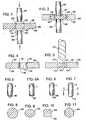
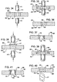
- FIGS. 1 though 4 illustrate the manufacture of a desired working hole H W , the shape of which is indicated by bushing 206 having, after hole formation, internal sidewall portions 198 extending through a metal structure 200 between obverse 202 and reverse surfaces 204.
- This technique of manufacture of a working hole H W can be utilized for providing, repairing, or repositioning a hole H in a metal 200.
- the first step in such a method is providing a selected hole of suitable size and shape through the structure 200 from the obverse surface 202 to the reverse surface 204, by (i) inspection and acceptance of sidewall portions 208 of a pre-existing hole to provide a selected starting hole H 1 , or (ii) enlargement or rework of a pre-existing hole to provide at least some new sidewall portions to provide a selected starting hole H 1 , or (iii) if no hole exists, providing a new starting hole with new sidewall portions to provide a selected starting hole H 1 .
- a physically deformable metal insert 206 is provided having a body portion 207.
- the insert 206 is sized and configured so as to be capable of frictionally engaging the sidewall portions of the selected starting hole 208.
- the body portion 207 has first 212 and second 214 ends and peripheral wall 216 extending for a length between said first 212 and second 214 ends to permit the body portion 207 to be inserted at least partially within the selected starting hole 208. Then, the deformable metal insert 206 is inserted into the selected starting hole 208 so that the body portion 207 extends at least partially within the selected starting hole 208 and the peripheral wall 216 of the insert 206 is adjacent at least a portion of the sidewall of the hole 208.
- the insert After insertion of the insert 206, the insert is subjected to physical deforming forces to cause the insert 206 to be deformed and to frictionally engage at least some of the sidewall portions of the selected hole 208, and to cause at least a portion of the body portion 207 of the insert 206 to be radially displaced and at least some of said metal structure 200 adjacent hole 208 to be radially displaced sufficient to cause at least some of the sidewall portions of said selected starting hole 208 to exert compressive forces against the sidewall 216 of the insert 206 to a degree sufficient to enhance fatigue life of the hole 208 surrounding the insert 206 and to substantially fix the insert 206 within the selected starting hole 208.
- the physically deformation of the insert 206 may include making indentations 211 and 213 in insert 206 via use of indenters, further discussed herein below.
- the method further includes the step of forming a working hole H W axially through the insert 206, using a suitable tool such as drill 217, extending through insert 206 from the first end 212 to the second end 214 of the insert 206.
- the insert 206 may, but not necessarily, be provided in a cylindrical configuration, as indicated in FIG. 16. Accordingly, the insert 206 can also be provided in a suitable non-cylindrical configuration when appropriate.
- an insert 236 can be provided in an eccentric configuration, such as in a shape having an elliptical configuration, in cross-section.
- a circular drill can be utilized to provide a working hole H W having a cylindrical configuration.
- the sidewall portions 240 of a starting hole 242 can be provided with a countersink shoulder 244.
- an insert 245 further includes, at either the first 246 or second 248 end, a countersink head portion 250. After milling, a new first end 246' may be provided, flush with first surface 202, as indicated in FIG. 81.
- an insert 206 is provided sized and shaped wherein after insertion, the insert 206 is positioned in a flush configuration with respect to the first 202 and second 204 surfaces of the metal structure 200 to provide working hole H W .
- another insert 206' is positioned in an underflush configuration with respect to the first 202 and second 204 surfaces of the structure 200 to provide working hole H W' .
- FIG. 55 Alternately, in FIG.
- FIG. 56 another insert 206" is positioned in a double underflush configuration with respect to the first 200 and second 202 surfaces of the structure 200 to provide working hole H W" .
- FIG. 56 Yet another configuration is shown in FIG. 56, where, after insertion the insert 206'" is positioned in an overflush configuration with respect to the first 202 and second 204surfaces of the metal structure 200.
- an insert 206"" is positioned in a double overflush configuration with respect to the first 202 and second 204 surfaces of the structure 200, to provide a working hole H W"" .
- a suitable method may include, after subjecting the insert to physical deforming forces, the step of removing at least some of an overflush portion of the insert via a milling or other suitable machine operation.
- a milling or other suitable machine operation may be conducted using a mill 251 on a flat metal structure 200 as in FIG. 65, or a beveled metal structure 200' as seen in FIG. 67, or with a curved metal structure 200" as seen in FIGS. 71 and 72.
- the milled end is flush with either the first 202 or second 204 surface of the structure, respectively, for example if structure 200 is used.
- a flush insert 260 can be provided having an external flanged head portion 262.
- an underflush insert 260' can be provided having an external flanged head portion 262 extending radially outward from the hole H W .
- an overflush insert 260" can be provided having an external flanged head portion 262.
- a suitable working hole H W , H W' , or H W" can be provided in desired final dimensions.
- inserts can be provided with a flange which includes nut retaining elements suitable for use in a nut plate assembly, as indicated in FIGS. 62-64.
- the flange 270 including nut retaining element 272 is provided on a bushing 274 which is mounted flush with the upper surface 202 of metal structure 200.
- the flange 207 including nut retaining element 272 for retaining a floating nut 273 is provided with a bushing 274' which mounted in an underflush configuration with respect to the lower surface 204 of metal structure 200.
- FIG. 62 the flange 270 including nut retaining element 272 is provided on a bushing 274 which is mounted flush with the upper surface 202 of metal structure 200.
- the flange 207 including nut retaining element 272 for retaining a floating nut 273 is provided with a bushing 274' which mounted in an underflush configuration with respect to the lower surface 204 of metal structure 200.
- a non-circular feature can be provided in the body portion of an insert, and a complementary shape provided in a hole, for deformation of the insert within the selected hole for any of the various configurations shown in FIG. 54 through 66, and in such an event, the non-circular features extends axially from the first surface 202 to the second surface 204 adjacent the selected hole H W . In such cases, the hole.
- the metal structure 200 can be a flat structure having uniform cross-sectional dimension adjacent said selected hole 216.
- the metal structure 200' can have a non-uniform cross-sectional dimension adjacent said selected hole 298, including a beveled shape as shown in these FIGS. 67-70.
- a metal structure 200" can be curved.
- the step of subjecting the insert to physical deforming forces includes the use of a first indenter 280 to act on the first end 212 of the insert such as insert 206 shown in FIG. 1.
- the step of subjecting the insert 206 to physical deforming forces includes the use of a second indenter 282 to act on the second end 214 of an insert such as insert 206 in FIG. 1.
- Various indenter shapes may be provided, some of which are indicated in FIGS. 5 through 11.
- the first indenter 280 or second indenter 282 can be provided, where appropriate, in a non-round cross-section such as those indicated in FIGS.
- an eccentric indenter shape 290 is provided, a rectangular shape 292 with radiused corners 293 is provided, and a polygonal shape 294 (here, hexagonal) indenter shape is provided.
- a polygonal shape 294 hexagonal
- FIG. 8 For most common cylindrical inserts, or for ring-like bushings, the use of an indenter with circular cross-section 296 as shown in FIG. 8 is provided. More commonly, many applications will benefit with use of a generally cylindrical indenter "I" as shown in FIGS. 5, 5A, 6, and 7, but with various working ends, such as a at least partially conical 300 as shown in FIG. 5, or a smooth, uniform pressure profile curve 302 as shown in FIG.
- an indenter 308 having an at least partially spherical working end 310 is useful, as indicated in FIG. 7.
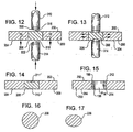
- FIGS. 12 and 13 Yet further useful indenter shapes are shown in FIGS. 12 and 13, where first 312 and second 314 indenters are shown with a rounded face 316 and 318, respectively, and sloping sidewalls 320 and 322, respectively.
- indentations 211' and 213' are provided by the indenters 312 and 314, respectively.
- Similar embodiments are provided in FIGS. 18 and 19, but with force and in a metal sufficient to cause deeper indentations 211" and 213", when starting with a generally H-shaped ring-like insert 327 having pre-existing indentations 328 and 329, which are configured to match, at least in part, the indenter sidewall shapes 320 and 322.
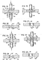
- FIGS. 23 and 23 A still further embodiment for useful indenter shapes is provided in FIGS. 23 and 23, where first 332 and second 334 indenters are shown with a flat face 336 and 338, respectively, and long sloping sidewalls, 340 and 342, respectively.
- the long sloping sidewalls 340 and 342 are designed to match a preformed sidewalls 346 and 348 in ring-like insert 350 that has a cross-sectional profile of opposing pentagons, much in the shape of a baseball plate with the apex 349 of each in opposition at the axial center of the insert ring 350.
- insert 350 is deformed to the shape illustrated in FIGS.
- drill 217 is utilized in the manner shown elsewhere to prepare the final, finished annular bushing in metal structure 200 as indicated in FIG. 25.
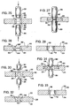
- FIGS. 26 and 27 Yet another embodiment for useful indenter shapes is provided in FIGS. 26 and 27, wherein first 362 and second 364 indenters are shown with a flat face 366 and 368, and stops 367 and 369, respectively, and long sloping sidewalls 340 and 342, respectively.
- the long sloping sidewalls 340 and 342 are designed to match preformed sidewalls 346 and 348 in a ring-like insert 350.
- insert 350 is deformed to the shape illustrated in FIGS.
- drill 217 is utilized in the manner shown elsewhere to prepare the final, finished annular bushing in metal structure 200 as indicated in FIG. 29.
- FIGS. 30 and 31 A still further embodiment for useful indenter shapes is provided in FIGS. 30 and 31, wherein first 382 and second 384 indenters are shown with a flat face 386 and 388, and cylindrical pilot nose portions 390 and 392, shaped and sized to fit in complementary sliding engagement with a central aperture 394 defined by interior sidewall 396 in annular bushing 398.
- insert 398 is deformed to the shape illustrated in FIGS. 31 and 32, wherein the opposing indenters 382 and 384 have shaped indentations 400 and 402 (formed by faces 386 and 388) in insert 398.
- the insert 398 has been deformed radially outward in the direction of reference arrows 352 outwardly to compress the hole edgewall portion 354 of metal structure 200.
- drill 217 is utilized in the manner shown elsewhere to prepare the final, finished annular bushing in metal structure 200 as indicated in FIG. 33.
- FIGS. 34 and 35 A still further embodiment for useful indenter shapes is provided in FIGS. 34 and 35, wherein first 410 and second 412 indenters are shown with a flat face 414 and 416 for acting on an annular bushing insert 420.
- insert 420 is deformed to the shape illustrated in FIGS. 35 and 36, wherein the opposing indenters 410 and 412 have shaped indentations 422 and 424 (formed by faces 414 and 416) in insert 420.
- the insert 420 has been deformed radially outward in the direction of reference arrows 352 outwardly to compress the hole edgewall portion 354 of metal structure 200.
- drill 217 is utilized in the manner shown elsewhere to prepare the final, finished annular bushing insert in metal structure 200 as indicated in FIG. 37.
- first 410 and second 412 indenters are shown with a flat face 414 and 416 for acting on obverse 417 and reverse 418 sides of a flanged, solid insert 440.
- insert 440 is deformed to the shape illustrated in FIGS. 39 and 40, wherein the opposing indenters 410 and 412 have shaped indentations 442 and 444 (formed by faces 414 and 416) in insert 440.
- the insert 440 has been deformed radially outward in the direction of reference arrows 352 outwardly to compress the hole edgewall portion 354 of metal structure 200.
- drill 217 is utilized in the manner shown elsewhere to prepare the final, finished annular bushing insert 450 having annular walls 452 with a interior wall portion 454 in metal structure 200 as indicated in FIG. 37.
- FIGS. 78 and 79 Another useful indenter shape is shown in FIGS. 78 and 79, wherein indenters 460 and 462 having flat bottoms 464 and 466 utilizes radiused edges 468, shown as radius R 1 in FIG. 78.
- Flanged bushings 500 including nutplate retaining elements 502 can be similarly formed, as shown by deformation of flanged bushing inserts 500 illustrated in FIGS. 42-45.
- first 504 and second 506 indenters are shown with a flat face 508 and 510 for acting on obverse 512 and reverse 514 sides of a flanged, solid insert 500 with nutplate retaining elements 502.
- insert 500 is deformed to the shape illustrated in FIGS. 43 and 44, wherein the opposing indenters 504 and 506 have shaped indentations 516 and 518 (formed by faces 508 and 510) in insert 500.
- the insert 500 has been deformed radially outward in the direction of reference arrows 352 outwardly to compress the hole edgewall portion 354 of metal structure 200.
- drill 217 is utilized in the manner shown elsewhere to prepare the final, finished annular bushing insert 520 having annular walls 522 with a interior wall portion 524 in metal structure 200 as indicated in FIG. 45. Also shown in FIG. 45 is a floating nut 526 in working location in place in nutplate retaining element 502.
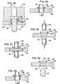
- a further enhancement of the method just shown in FIGS. 42 to 45 additionally includes the use of a flange retention tool 530 that secures the flange 532 adjacent said first surface 202 of the metal structure 200 during the step of subjecting the insert 500 to physical deforming forces, so that the flange 532 is maintained in a position in contacting engagement with the first surface 202 of the metal structure 200.
- a flange retention tool 530 secures the flange 532 adjacent said first surface 202 of the metal structure 200 during the step of subjecting the insert 500 to physical deforming forces, so that the flange 532 is maintained in a position in contacting engagement with the first surface 202 of the metal structure 200.
- the one shown here includes a central axial passageway 534 through which first indenter freely passes, and a flange engaging annular ledge 536 (appears as two ledges in cross-sectional view) having a lower side portion that is in firm restraining engagement with an upper end portion 538 of nut retention element 502.
- a foot portion 540 of retention tool 530 engages against first surface 202 of metal structure 200, in order to further prevent surface upset during the indenting step.
- the retention tool 530 is also useful to retain the insert 500 during the step of forming a finished hole by drilling out excess material from the interior of insert 500.
- FIG. 49 where the nut retention element 538 is shown configured to secure nut 540. Also, note that in the embodiment of this method shown in FIGS. 46-49, a generally H-shaped insert 500 was provided for starting the nutplate installation process.
- FIGS. 50 through 53 a similar operation is provided, but now starting with a solid flanged insert 550 having a nut retention element 538.
- Indenters 504 and 506 act on insert 550, in the manner described above, to create residual stress in the manner herein above described, leaving behind indentations 552 and 554.
- the working hole H W is formed via drilling out the indentations 552 and 554 with drill 217.
- a finished flanged bushing 550' having a nut retention element 538 thereon is provided holding nut 540.
- a similar apparatus and method is utilized for beveled or sloping metal surfaces such as surface 200' as indicated in FIGS. 67 through 70.
- indenters 504 and 506 act as previously described to form indentations 552 and 554.
- the bushing 550 sticks down below the lower sloping surface 560 at the start of the nut installation process.
- a milling device 251 is used to machine away the excess portion 562 of bushing 550, so that a new, sloping lower end 564 is provided for bushing 560 that matches the profile of sloping surface 560.
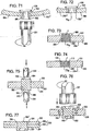
- a flanged bushing 580 with nut retention element 538 is shown installed in a curved metal structure 200".
- a milling operation is provided with tool 251 to remove the overflush end 582 of bushing 580, to provide a finished, installed flanged bushing 580' on in the curved metal structure 200" in a manner that the machined lower end 582' of bushing 580 is flush with lower surface 584 of structure 200".
- FIGS. 73 and 74 Attention is now directed to FIGS. 73 and 74.
- FIG. 73 the structure first shown in FIG. 41, with upper flange 586, is now shown including the further step of installing a threads T in the working hole H W .
- FIG. 74 the structure first shown in FIG. 4 that has an annular bushing installed flush with surfaces 202 and 204 in structure 200, now is shown including the further step of installing threads T in the working hole H W .
- FIGS. 75-78 wherein a double overflush solid plug insert 590 with sidewalls 592 and first end 594 and second end 596 is shown ready for deformation in a selected starting hole 598 in metal structure 200 comprised of one or more layers 200 1 , 200 2 , etc., in a series from 200 1 to 200 x , where x is equal to the number of layers.
- Deformation via indenters 504 and 506 results in formation of indentations 600 and 602 in the insert 590.
- mill 251 or other suitable means the excess material on the first end 594 is removed to form a new first end 594' that is flush with the upper surface 202 of structure 200.
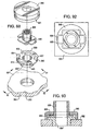
- FIG. 82 provides a bottom perspective view of a insert 700 with barrel portion 702, flange 704 and anti-rotation feature 706 for installation on a metal structure 200 for affixing a nutplate thereto.
- the anti-rotation feature is configured press fitting engagement with the first surface 202 of the metal structure 200 upon receipt of deforming forces which act against the insert in the manner further explained in FIGS. 83-87 below.
- a cylindrical barrel design is shown for a nutplate blank, such nutplate blanks can also be provided utilizing a generally H-shaped ring insert (see FIG. 18) or ring-like opposing pentagonal cross-sectional design (see FIG. 22).
- FIGS. 83 through 85 show the use of a first compound indenter 720 and a second compound indenter 722 for installation of the nutplate blank insert 700 on a metal structure 200.
- First compound indenter 720 includes a center indenter portion 724 having an inner contact end 725, and an outer, preferably annular indenter portion 726 having a outer contact end 728.
- the second compound indenter 730 includes a center indenter portion 734 having an inner contact end 735 and an outer indenter portion 736 having an outer contact end 738.
- the insert 700 is placed into a selected starting hole 740 defined by edgewall portions 742 in structure 200.
- both the first and second compound indenters 720 and 730 use their respective outer indenter portions 726 and 736 as a foot or stop against adjacent surface (the top 750 of blank 700 in the case of first indenter 720, and the lower surface 204 in the case of second indenter).
- the outer foot portions are configured to engage and confine said the second surface of the metal structure 200 when the first indenter acts on the insert.
- outer the foot portions of the first indenter are configured to engage and confine the upper surface of the insert 700 when the inner or center indenter of the second compound indenter acts on the insert 700. While maintaining the foot portions 726 and 736 in their contact positions, the center indenters are used in opposing fashion to place indentations 752 and 754 in blank 700, to expand the base 702 in the manner described hereinabove.
- FIG. 86 the step of removing unneeded material via drill 217 is shown.
- the finished, mounted nutplate 700' is shown in place on structure 200, having an annular hole defining portion 760 with inner sidewall 762.
- a solid or plug body portion has been provided in nutplate blank 700, it should be understood that a bushing type nutplate blank can also be utilized, as well as H or ring-like plug designs as variously described hereinabove.
- a further step in the method may include the additional step, prior to the step of inserting the insert into the metal substrate, of roughening the peripheral wall of an insert to a preselected roughness, in the manner indicated in FIG. 109 below.
- roughening has been shown to increase the fatigue life, in some cases by as much as a factor of two over a bushing-like member of similar configuration that has not been similarly roughened.
- the roughened surface of the plug and bushing like member decreases the amount of slip, under load, between its exterior surface and the surface of the hole in which it is installed. Reducing the slip between the two surfaces reduces the amount of fretting.
- Fretting is defined as the relative oscillatory motion between two touching surfaces where such motion causes damage to one or both of the surfaces. Fretting is a known factor in the initiation of cracks. By minimizing the fretting, and thus minimizing subsequent cracking, the overall fatigue life of a structure is enhanced when a roughened peripheral surface of the plug or bushing is provided.
- the step of roughening the peripheral wall of an insert may be accomplished by blasting the peripheral wall with air entrained media, such as sand, garnet, or other suitable materials. Alternately, the step of roughening the peripheral wall of the insert may be accomplished by tumbling the insert in a roughening media.
- the roughness of the peripheral wall is desirably from about 3.175 ⁇ m (125 micro-inches) to about 6.35 ⁇ m (250 micro-inches). In other materials and applications, the roughness of the peripheral wall is at least 6.35 ⁇ m (250 micro-inches).
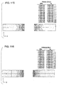
- the bushing 790 has a roughness in peripheral wall 800 that is indicated by the many miniature indentation representations 802. Additionally, as indicated in FIG. 110, it is sometimes also desirable to include a further step, prior to the step of inserting the insert such as insert 790 into said metal substrate, of providing a microencapsulated glue 804 on the peripheral wall 800 of the insert 790.
- the outer peripheral wall 810 of bushing 812 includes a plurality of micro-fluting knurls, such as between 30 and 120 fluting pairs (ridge 814 and valley 816) per inch. Ideally, such pairs include radiused corners 818 between ridges 814 and valleys 816.
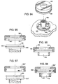
- FIGS 88-93 a nut plate with novel nut retaining element attachment method is shown.
- the nut plate 830 is first installed in structure 200 using the method of deformation with opposing indenters described earlier (the method is also repeated in FIGS. 89 through 91 wherein uniform pressure profile type first and second indenters I1 and I2 are shown, to create indentations 816 and 818, which are subsequently drilled out to provide a hollow nutplate bushing 830').
- the nut plate 830 has a recess 832 in the upper portion 834 of its outwardly extending flange 838 that can be selected to match a desired nut element 836 footprints as defined by tabs 838.
- a "nut element” 836 is a term that describes any threaded component that retains a fastener. Matching the dimensions of the nut footprint 838 perimeter with the recess 832 usually is configured to allow for the nut element 836 to float by at least about 0.50mm (0.020 inches) radially in any direction. Such float facilitates fastener installation.
- the nut element 836 is then placed into the nut plate flange recess 832. In this configuration, a retaining cap 840 is then snapped over the vertical exterior 842 of the nut plate flange 837 to secure the nut element 836.
- the retaining cap 840 includes features such as inter-engaging ridges 841, to fit with grooves 843 in vertical flange 842, to provide for a secure fit precluding plush out of the nut element 836 during fastener installation.
- features such as inter-engaging ridges 841, to fit with grooves 843 in vertical flange 842, to provide for a secure fit precluding plush out of the nut element 836 during fastener installation.
- the use of a matching half-cylinder notch ring in the nutplate, and matching protrusion in the interior of the retaining cap 840 is provided.
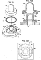
- FIGS. 97 and 98 another embodiment is shown in which the cap 840' utilizes a catchment lip 860 which acts against a catchment ledge lip 843' in nutplate 840'.
- the retaining cap 840' is forced onto the nut plate 830' flange, snapping it into place over the catchment ledge lip 843'.
- This provision of a series of "one-way" sheared features provide for easy installation. The angle of the sheared elements make it easy for the retaining ring to slip over the nut plate flange, but make it difficult to remove, giving it a high resistance to push out forces from fastener installation.
- FIGS 99 through 102 the steps of installing a nut plate with novel element attaching methods for a sealed installation are provided.
- the dome 900 feature of the retaining device prevents fluid from penetrating the wall surface 202 to which the nut plate is secured.
- the nut plate base is first installed using the method of pressing with opposing indenters, as described above, to provide an installed nutplate base 830'.
- the nutplate has a recess 832 in its upper flange that can be provided to match standard nut element footprints; here a nutplate is shown located in the flange.
- the dimensions of the matching perimeter of the recess allow for the nut element to float by at least 0.50 mm (0.020 inches) radially in any direction.
- the float facilitates fastener installation.
- the nut element is then placed into the nut plate flange recess 832.
- the domed retaining device 900 is then snapped over the exterior of the nut plate flange to secure the nut element 836.
- the domed retaining device 900 has features along the sides that provide for a secure fit precluding push out of the nut element during fastener installation, such as the groove/ridge design just discussed above.
- the dome 900 also has an integral seal ring 902 that runs around the periphery 904 of the base of the domed element 900. Ring 902 may include grooved and/or ridged 903 elements necessary to form a secure seal.
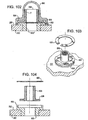
- FIGS. 104 -106 yet another nut plate design is illustrated, here utilizing an internal snap ring 920 as the means to retain the nut element 836.
- the nutplate 830 is first installed using the methods of pressing a plug or bushing element with opposing indenters as described earlier above.
- the nut plate 830 has a recess 832 in its flange 834 that can be configured to match standard nut element footprints.
- the dimensions of the matching perimeter of the recess allow for the nut element 836 to float by at least 0.50mm (0.020 inches) radially in any direction. The float facilitates fastener installation.
- the nut element 836 is then placed into the nut plate flange recess 832.
- a snap ring 920 is then snapped into an interior groove 922 in the interior of the nut plate flange 834 to secure the nut element 836. Further details of the use of this snap-ring for securing a nut on a nutplate are illustrated in FIGS. 104, 105, and 106. In particular, note the location of the snap ring as shown in FIG. 106.
- an o-ring seal 940 can be utilized to provide a separately mounted flange 942 for attachment on a plug 944.
- a countersink head 946 can be used at the bottom at surface 204.
- a locking pattern 948 can be used in the flange head 950 for securing the flange in place during installation.
Landscapes
- Engineering & Computer Science (AREA)
- Mechanical Engineering (AREA)
- General Engineering & Computer Science (AREA)
- Insertion Pins And Rivets (AREA)
- Connection Of Plates (AREA)
- Bolts, Nuts, And Washers (AREA)
- Diaphragms For Electromechanical Transducers (AREA)
- Paper (AREA)
- Road Signs Or Road Markings (AREA)
- Golf Clubs (AREA)
Claims (74)
- Verfahren zur Anbringung eines Befestigungselements an einer Metallstruktur (200), welche Struktur eine vordere (202) und eine rückwärtige (204) Oberfläche aufweist, und in der ein ausgewähltes Loch (208) zur Anbringung des Befestigungselements vorgesehen ist, welches ausgewählte Loch durch Seitenwandteile (208) definiert ist, welche sich durch die Struktur von der vorderen Oberfläche zur rückwärtigen Oberfläche der Struktur erstrecken, wobei das Verfahren die Schritte aufweist:a) Bereitstellung eines ausgewählten Lochs passender Dimension und Gestalt durch die Struktur von der vorderen Oberfläche zur rückwärtigen Oberfläche, durchi) Begutachtung und Abnahme von Seitenwandteilen eines bereits bestehenden Loches zur Ausbildung eines ausgewählten Lochs oderii) Vergrößerung oder Nacharbeit eines bereits bestehenden Lochs zur Ausbildung von mindestens einigen Seitenwandteilen zur Ausbildung eines ausgewählten Lochs, oderiii) falls kein Loch besteht, Ausbildung eines neuen Lochs mit neuen Seitenwandteilen durch die Struktur zur Ausbildung eines ausgewählten Lochs;b) Bereitstellung einer physikalisch formbaren Metalleinlage (206) mit einem Körperteil (207), welche physikalisch formbare Metalleinlage im verformten Zustand dimensioniert und angeordnet ist, um die Seitenwandteile des ausgewählten Lochs (208) reibschlüssig zu berühren, wobei der Körperteil ein erstes (212) und ein zweites (214) Ende aufweist, und sich eine Umfangswand (216) über die Länge zwischen dem ersten und zweiten Ende erstreckt, damit der Körperteil zumindest teilweise in das ausgewählte Loch eingeführt werden kann;c) Einführung der verformbaren Metalleinlage in das ausgewählte Loch, so dass sich der Körperteil zumindest teilweise innerhalb des ausgewählten Lochs erstreckt und die Umfangswand der Einlage zumindest teilweise an der Seitenwand des Lochs anliegt;d) Nach der Einführung Aufbringen physikalischer Verformkräfte auf die Einlage, so dass die Einlage verformt wird und reibschlüssig zumindest teilweise an den Seitenwandteilen des ausgewählten Lochs angreift, und der Körperteil der Einlage zumindest teilweise radial versetzt wird und die Struktur zumindest teilweise ausreichend radial versetzt wird, um die Seitenwandteile des ausgewählten Lochs zumindest teilweise Druckkräften gegen die Einlage in einem ausreichenden Maß auszusetzen, um die Lebensdauer unter Ermüdungsbeanspruchung des den Körper der Einlage umgebenden Lochs zu erhöhen und die Einlage im Wesentlichen innerhalb des ausgewählten Lochs zu fixieren;e) Bereitstellung eines Mutterelements (836) als das Befestigungselement; undf) Sicherung des Mutterelements an der Struktur, wodurch die Struktur eine Annietmutter-Basis ausbildet.
- Verfahren gemäß Anspruch 1, das den weiteren Schritt (e) zur Ausformung eines Arbeitslochs (HW) axial durch die Einlage (206) aufweist, welches Arbeitsloch sich durch die Einlage vom ersten Ende zum zweiten Ende der Einlage erstreckt.
- Verfahren gemäß Anspruch 1, bei dem die Einlage eine zylindrische Ausführung aufweist.
- Verfahren gemäß Anspruch 1, bei dem die Einlage eine nicht-zylindrische Ausführung aufweist.
- Verfahren gemäß Anspruch 4, bei dem die Einlage im Querschnitt eine exzentrische Ausführung aufweist.
- Verfahren gemäß Anspruch 5, bei dem die Einlage im Querschnitt eine elliptische Ausführung aufweist.
- Verfahren gemäß Anspruch 2, bei dem das Arbeitsloch (HW) eine zylindrische Ausführung aufweist.
- Verfahren gemäß Anspruch 3, bei dem die Seitenwandteile des Lochs weiter entweder an erster oder zweiter Oberfläche der Struktur anliegend eine Senkungsschulter (244) aufweisen.
- Verfahren gemäß Anspruch 8, bei dem die Einlage weiter entweder am ersten oder am zweiten Ende einen Senkkopfteil (250) aufweist.
- Verfahren gemäß Anspruch 1, bei dem die Einlage nach der Einführung bezüglich der ersten und zweiten Oberflächen der Struktur in einer bündigen Ausführung positioniert ist.
- Verfahren gemäß Anspruch 1, bei dem die Einlage nach der Einführung bezüglich der ersten und zweiten Oberflächen der Struktur in einer unterbündigen Ausführung positioniert ist.
- Verfahren gemäß Anspruch 1, bei dem die Einlage nach der Einführung bezüglich der ersten und zweiten Oberflächen der Struktur in einer doppelt unterbündigen Ausführung positioniert ist.
- Verfahren gemäß Anspruch 1, bei dem die Einlage nach der Einführung bezüglich der ersten und zweiten Oberflächen der Struktur in einer überbündigen Ausführung positioniert ist.
- Verfahren gemäß Anspruch 1, bei dem die Einlage nach der Einführung bezüglich der ersten und zweiten Oberflächen der Struktur in einer doppelt überbündigen Ausführung positioniert ist.
- Verfahren gemäß Anspruch 13 oder Anspruch 14, welches weiter nach Aufbringung physikalischer Verformkräfte auf die Einlage den Schritt zum zumindest teilweisen Entfernen des überbündigen Teils der Einlage aufweist.
- Verfahren gemäß Anspruch 15, bei dem bei Beendigung des Schritts des Entfernens entweder das erste oder das zweite Ende der Einlage bezüglich entweder der ersten oder zweiten Oberfläche der Struktur bündig ist.
- Verfahren gemäß Anspruch 1, bei dem die Einlage weiter einen äußeren Kopfteil aufweist, welcher äußere Kopfteil ein von besagtem Loch nach außen erstreckenden Flanschteil aufweist.
- Verfahren gemäß Anspruch 1, bei dem das ausgewählte Loch darin mindestens ein nicht rundes Element ausgeformt hat, welches sich axial von der ersten Oberfläche zur zweiten Oberfläche des ausgewählten Lochs erstreckt.
- Verfahren gemäß Anspruch 18, bei dem der Körperteil der Einlage vor Deformation selbiger ein Element komplementär zu dem mindestens einem nicht-runden Element im ausgewählten Loch aufweist.
- Verfahren gemäß Anspruch 1 oder Anspruch 18, bei dem der Schritt der Aufbringung physikalischer Verformkräfte auf die Einlage die Verwendung eines ersten Stempels, welcher auf das erste Ende der Einlage wirkt, aufweist.
- Verfahren gemäß Anspruch 20, bei dem der Schritt der Aufbringung physikalischer Verformkräfte auf die Einlage die Verwendung eines zweiten Stempels, welcher auf das zweite Ende der Einlage wirkt, aufweist.
- Verfahren gemäß Anspruch 20, bei dem der erste Stempel einen nicht runden Querschnitt aufweist.
- Verfahren gemäß Anspruch 21, bei dem der zweite Stempel einen nicht runden Querschnitt aufweist.
- Verfahren gemäß Anspruch 1, bei dem die Metallstruktur eine flache Struktur aufweist, die anliegend am ausgewählten Loch im Querschnitt gleichmäßige Ausmaße aufweist.
- Verfahren gemäß Anspruch 1, bei dem die Metallstruktur anliegend am ausgewählten Loch im Querschnitt ungleichmäßige Ausmaße aufweist.
- Verfahren gemäß Anspruch 25, bei dem die Metallstruktur angefast ist.
- Verfahren gemäß Anspruch 25, bei dem die Metallstruktur abgerundet ist.
- Verfahren gemäß Anspruch 9, bei dem der Kopfteil der Einlage eine kegelstumpfförmige Ausführung besitzt und bei dem der Körperteil der Einlage eine zylindrische Ausführung besitzt.
- Verfahren gemäß Anspruch 17, welches weiter die Bereitstellung eines Flanschrückhalteelement aufweist, das den Flansch anliegend an erster Oberfläche der Metallstruktur während des Schritts des Aufbringens physikalischer Verformkräfte auf die Einlage sichert, so dass der Flansch in einer Position in berührendem Eingriff mit der ersten Oberfläche der Metallstruktur gehalten wird.
- Verfahren gemäß Anspruch 1 oder Anspruch 29, bei dem der Schritt der Aufbringung physikalischer Verformkräfte auf die Einlage in einem einzigen Stempelschritt unter Verwendung mindestens eines Stempels ausgeführt wird.
- Verfahren gemäß Anspruch 2, bei dem während der Ausformung des Arbeitslochs eine Stütze zumindest teilweise gegen das entweder erste oder zweite Ende des Stempels platziert wird, wodurch die axiale Bewegung der Einlage während der Ausformung des Arbeitslochs unterbunden wird.
- Verfahren gemäß Anspruch 2, bei dem die Einlage weiter einen äußeren Flanschteil aufweist und bei dem während der Ausformung des Arbeitslochs eine Stütze zumindest teilweise gegen den äußeren Flanschteil platziert wird, wodurch die axiale Bewegung der Einlage während der Ausformung des Arbeitslochs unterbunden wird.
- Verfahren gemäß Anspruch 20, bei dem der erste Stempel ein Arbeitsende mit flachem Boden aufweist.
- Verfahren gemäß Anspruch 20, bei dem der erste Stempel ein Arbeitsende mit (a) einem flachen Bodenteil und (b) sich von dem flachen Bodenteil nach außen erstreckende, abgeschrägte Seitenwandteile aufweist.
- Verfahren gemäß Anspruch 20, bei dem der erste Stempel ein Arbeitsende mit (a) einem flachen Bodenteil und (b) sich von dem flachen Bodenteil nach außen erstreckende, abgerundete Seitenwandteile aufweist.
- Verfahren gemäß Anspruch 20, bei dem der erste Stempel ein Arbeitsende mit einem Profil aufweist, welches eine gleichmäßige Druckverteilung auf das erste Ende der Einlage verursacht.
- Verfahren gemäß Anspruch 20, bei dem der erste Stempel ein Arbeitsende mit zumindest teilweise kugelförmigem Profil aufweist.
- Verfahren gemäß Anspruch 20, bei dem der erste Stempel ein Arbeitsende mit zumindest teilweise kegelförmigem Profil aufweist.
- Verfahren gemäß Anspruch 20, bei dem der erste Stempel ein Arbeitsende mit einem Führungszapfen aufweist.
- Verfahren gemäß Anspruch 2, bei dem der Schritt der Aufbringung physikalischer Verformkräfte auf die Einlage zur Verformung der Einlage eine oder mehrere physikalische Vertiefungen in der Einlage verursacht werden, und bei dem der Schritt der Bildung eines Arbeitslochs in der Einlage die physikalischen Vertiefungen entfernt.
- Verfahren gemäß Anspruch 17, bei dem der Flansch weiter ein Antirotationselement aufweist, und bei dem das Antirotationselement durch Presspassungseingriff mit der ersten Oberfläche der Metallstruktur bei der Aufnahme der Verformkräfte in die Einlage ausgeformt wird.
- Verfahren gemäß Anspruch 41, bei dem das Antirotationselement zumindest einen Teil eines nach unten herausragenden Rings aufweist.
- Verfahren gemäß Anspruch 20, bei dem der erste Stempel weiter einen Fußteil aufweist, welcher Fußteil ausgeführt ist, die erste Oberfläche der Metallstruktur zu erfassen und zu sperren wenn der erste Stempel auf die Einlage wirkt.
- Verfahren gemäß Anspruch 21, bei dem der zweite Stempel weiter einen Fußteil aufweist, welcher Fußteil ausgeführt ist, die zweite Oberfläche der Metallstruktur zu erfassen und zu sperren wenn der zweite Stempel auf die Einlage wirkt.
- Verfahren gemäß Anspruch 1, bei dem die Einlage einen röhrenförmigen Körperteil aufweist.
- Verfahren gemäß Anspruch 1, bei dem die Einlage einen massiven Körperteil aufweist.
- Verfahren gemäß Anspruch 1, welches weiter, vor dem Schritt der Einführung der Einlage in das Metallsubstrat, den zusätzlichen Schritt des Aufrauens der Umfangswand der Einlage auf eine vorbestimmte Rauheit aufweist.
- Verfahren gemäß Anspruch 47, bei dem der Schritt des Aufrauens der Umfangswand der Einlage die Bestrahlung der Umfangswand mit einem luftgetragenen Medium aufweist.
- Verfahren gemäß Anspruch 47, bei dem der Schritt des Aufrauens der Umfangswand der Einlage ein Rollen der Einlage in aufrauendem Medium aufweist.
- Verfahren gemäß Anspruch 47, bei dem die Rauheit der Umfangswand von 3,175 µm bis 6,35 µm beträgt.
- Verfahren gemäß Anspruch 47, bei dem die Rauheit der Umfangswand mindestens 6,35 µm beträgt.
- Verfahren gemäß Anspruch 1, welches weiter, vor dem Schritt der Einführung der Einlage in das Metallsubstrat, den zusätzlichen Schritt der Bereitstellung eines mikrogekapselten Klebstoffs auf der Umfangswand der Einlage aufweist.
- Verfahren gemäß Anspruch 9, bei dem der Senker während dem Schritt (d) in einer überbündigen Ausführung eingebracht wird.
- Verfahren gemäß Anspruch 2, welches weiter den Schritt der Ausformung von Gewindegängen im Arbeitsloch aufweist.
- Verfahren gemäß Anspruch 45, bei dem der röhrenförmige Körperteil eine innere Seitenwand aufweist und bei dem die innere Seitenwand weiter den Schritt der Ausformung von Gewindegängen in der inneren Seitenwand des röhrenförmigen Körperteils aufweist.
- Ein hergestellter Gegenstand aufweisend:(a) eine Metallstruktur (200), welche Struktur eine vordere Oberfläche (202), eine rückwärtige Oberfläche (204), und ein sich dazwischen erstreckendes und durch einen Eckwandteil definiertes Durchgangsloch (208) aufweist;(b) einen Zapfen (206), welcher Zapfen eine äußere Zylinderoberfläche aufweist, welche Oberfläche vor der Installation in Größe und Form zum Eckwandteil komplementär ist, welcher Zapfen in die Metallstruktur durch radial nach außen gerichtete Ausdehnungen des Zapfens gegen das Eckwandteil eingebracht wird, um diesbezüglich eine Passung mit Übermaß herzustellen; und(c) bei dem der Zapfen weiter ein Annietmutterspielelement aufweist, welches Annietmutterspielelement eine nach oben gerichtete Fläche zur Stützung einer Mutter aufweist.
- Gegenstand gemäß Anspruch 56, bei dem die Zylinderoberfläche eine aufgeraute Oberfläche aufweist.
- Gegenstand gemäß Anspruch 57, bei dem die aufgeraute Oberfläche eine Rauheit von 3,175 µm bis 6,35 µm aufweist.
- Gegenstand gemäß Anspruch 57, bei dem die aufgeraute Oberfläche eine Rauheit von mindestens 6,35 µm aufweist.
- Gegenstand gemäß Anspruch 56, bei dem die Zylinderoberfläche eine geriffelte Oberfläche aufweist.
- Gegenstand gemäß Anspruch 56, bei dem die Zylinderoberfläche des Zapfens eine gerändelte Oberfläche aufweist.
- Gegenstand gemäß Anspruch 56, bei dem der Zylinder des Zapfens von nicht runder Gestalt ist.
- Gegenstand gemäß Anspruch 62, bei dem der Zylinder des Stutzens von exzentrischer Gestalt ist.
- Gegenstand gemäß Anspruch 56, welcher weiter einen Halteaufsatz aufweist, welcher Halteaufsatz das Mutterelement auf dem Zapfen hält.
- Gegenstand gemäß Anspruch 56, bei dem der Zapfen weiter eine Auffangkantenlippe aufweist.
- Gegenstand gemäß Anspruch 65, welcher weiter (a) ein Mutterelement und (b) einen Halteaufsatz aufweist, um über die Auffangkantenlippe auf dem Zapfen einzurasten.
- Gegenstand gemäß Anspruch 56, bei dem der Zapfen weiter ein Annietmutterspielelement aufweist, welches Annietmutterspielelement eine nach oben gerichtete Fläche zur Aufnahme einer Mutter aufweist.
- Gegenstand gemäß Anspruch 67, bei dem der Zapfen weiter einen äußeren Flanschteil einschließlich einem Mutterrückhalteelement aufweist.
- Gegenstand gemäß Anspruch 68, welcher weiter einen Halteaufsatz aufweist, welcher Halteaufsatz eine innere Kante ausgeführt zum Einrasten über und passendem Eingriff mit einer äußeren Umfangsnut, welche auf dem äußeren Flanschteil des Mutterrückhalteelements sitzt, aufweist.
- Gegenstand gemäß Anspruch 69, bei dem der Halteaufsatz weiter einen unteren Ringteil mit einem Abdichtteil aufweist, welcher Abdichtteil zum Abdichten des Halteaufsatzes gegenüber der Struktur angebracht ist um eine wetterfeste Abdichtung bereitzustellen.
- Gegenstand gemäß Anspruch 67, bei dem das Annietmutterspielelement weiter eine nach innen gerichtete Ringnut aufweist, welche Ringnut zur Aufnahme eines Einrastrings dimensioniert und geformt ist.
- Gegenstand gemäß Anspruch 71, welcher weiter (a) ein Mutterelement und (b) einen Einrastring aufweist, und bei dem der Einrastring zum sicheren, passenden Eingriff mit der Ringnut in einer Art dimensioniert und geformt ist um das Mutterelement zu halten.
- Gegenstand gemäß Anspruch 56, bei dem der Zapfen weiter einen äußeren Flanschteil aufweist.
- Gegenstand gemäß Anspruch 73, bei dem der äußere Flanschteil einen nach unten gerichteten Abdichtring aufweist, welcher Abdichtring zur Aufnahme einer Dichtung dimensioniert und geformt ist, welche Dichtung gegen die Struktur gepresst wird, wenn der Flanschteil durch Pressung gegen die Struktur eingebracht wird.
Applications Claiming Priority (3)
| Application Number | Priority Date | Filing Date | Title |
|---|---|---|---|
| US305469 | 1989-02-01 | ||
| US10/305,469 US7516534B2 (en) | 2001-11-25 | 2002-11-25 | Method for attaching a nut element to a metal structure |
| PCT/US2003/020131 WO2004048073A1 (en) | 2002-11-25 | 2003-06-25 | Nut plates, and method for installation |
Publications (3)
| Publication Number | Publication Date |
|---|---|
| EP1590165A1 EP1590165A1 (de) | 2005-11-02 |
| EP1590165A4 EP1590165A4 (de) | 2006-03-15 |
| EP1590165B1 true EP1590165B1 (de) | 2007-11-14 |
Family
ID=32392446
Family Applications (1)
| Application Number | Title | Priority Date | Filing Date |
|---|---|---|---|
| EP03811987A Expired - Lifetime EP1590165B1 (de) | 2002-11-25 | 2003-06-25 | Annietmutter und einbauverfahren |
Country Status (6)
| Country | Link |
|---|---|
| US (1) | US7516534B2 (de) |
| EP (1) | EP1590165B1 (de) |
| AT (1) | ATE378167T1 (de) |
| AU (1) | AU2003249380A1 (de) |
| DE (1) | DE60317570D1 (de) |
| WO (1) | WO2004048073A1 (de) |
Cited By (1)
| Publication number | Priority date | Publication date | Assignee | Title |
|---|---|---|---|---|
| WO2021050644A1 (en) * | 2019-09-10 | 2021-03-18 | Sea Box, Inc. | Intermodal warehousing system |
Families Citing this family (41)
| Publication number | Priority date | Publication date | Assignee | Title |
|---|---|---|---|---|
| WO2003000455A1 (en) * | 2001-06-21 | 2003-01-03 | Black & Decker Inc. | Method and apparatus for fastening steel framing with a spin weld pin |
| DE10352126A1 (de) * | 2003-11-04 | 2005-08-04 | Metallwarenfabrik Hermann Winker Gmbh & Co. Kg | Befestigungselement |
| US7207352B2 (en) * | 2005-05-02 | 2007-04-24 | United Technologies Corporation | Bushing for thermally independent bypass air metering valve |
| DE102006011007A1 (de) * | 2005-12-16 | 2007-06-21 | Gühring Ohg | Schrumpffutter mit exzentrischer Positionierung |
| JP4761957B2 (ja) * | 2005-12-22 | 2011-08-31 | タマホーム 株式会社 | 鉄筋用ナット |
| JP5094140B2 (ja) * | 2006-11-09 | 2012-12-12 | 日野自動車株式会社 | 部材接合構造 |
| JP4972417B2 (ja) * | 2006-12-15 | 2012-07-11 | 日野自動車株式会社 | 部材接合方法及び構造 |
| FR2915913B1 (fr) * | 2007-05-09 | 2010-02-26 | Airbus France | Procede d'assemblage entre une piece en materiau metallique et une piece en materiau composite au moyen d'une fixation. |
| JP4513915B2 (ja) * | 2008-09-05 | 2010-07-28 | コニカミノルタビジネステクノロジーズ株式会社 | 板金部品の結合構造及び画像形成装置 |
| FR2956054B1 (fr) * | 2010-02-10 | 2012-04-27 | Snecma | Procede de reparation d'une bride d'un carter |
| US8661649B1 (en) * | 2010-10-24 | 2014-03-04 | The Boeing Company | Structurally integrated antenna aperture electronics attachment design and methodology |
| US8794910B2 (en) | 2011-02-01 | 2014-08-05 | United Technologies Corporation | Gas turbine engine synchronizing ring bumper |
| US8864450B2 (en) | 2011-02-01 | 2014-10-21 | United Technologies Corporation | Gas turbine engine synchronizing ring bumper |
| EP2675583B1 (de) | 2011-02-16 | 2020-06-17 | Keystone Synergistic Enterprises, Inc. | Verfahren zum verbinden und stärken von metallen durch mikrostrukturelle verbesserung |
| US8475099B2 (en) * | 2011-04-20 | 2013-07-02 | Varian Medical Systems, Inc. | Self-clinching blind floating fastener |
| US8875346B2 (en) * | 2011-06-28 | 2014-11-04 | Oakley, Inc. | Hinge assembly for eyewear |
| US20130094901A1 (en) * | 2011-10-18 | 2013-04-18 | Schaeffler Technologies AG & Co. KG | Radially aligned plates joined by compressive fit |
| USD701113S1 (en) * | 2011-12-30 | 2014-03-18 | Dimensional Innovations, Inc. | Recess plug |
| US9199437B2 (en) * | 2012-04-18 | 2015-12-01 | GM Global Technology Operations LLC | Panel assembly retainer and method of use |
| US9482115B2 (en) | 2012-08-23 | 2016-11-01 | United Technologies Corporation | Turbine engine support assembly including self anti-rotating bushing |
| KR20150120521A (ko) * | 2013-02-28 | 2015-10-27 | 린데 악티엔게젤샤프트 | 결빙-방지 처리 장치 및 방법 |
| US9863468B2 (en) | 2013-09-17 | 2018-01-09 | Sikorsky Aircraft Corporation | Rod end wear prevention |
| JP5955301B2 (ja) * | 2013-11-14 | 2016-07-20 | 株式会社神戸製鋼所 | 残留応力算出方法 |
| US9435362B2 (en) | 2014-03-05 | 2016-09-06 | Morgan Truck Body, Llc | Bolt and nut assembly with plastic cover for controlled sealing compression |
| DE102014204912A1 (de) * | 2014-03-17 | 2015-09-17 | Siemens Aktiengesellschaft | Verfahren zum Verschließen eines Loches und Bauteil |
| US20160068275A1 (en) * | 2014-09-09 | 2016-03-10 | Alcoa Inc. | Locking member with sealing insert and channel |
| GB2532444B (en) * | 2014-11-18 | 2018-06-06 | Corsaire Components Ltd | Apparatus for masking a nut plate during painting of an aircraft part containing the nut plate |
| US20160230599A1 (en) * | 2015-02-09 | 2016-08-11 | United Technologies Corporation | Flangeless conical sleeve and method of repair |
| JP6465482B2 (ja) * | 2015-02-19 | 2019-02-06 | 三菱航空機株式会社 | 貫通型フローティングナット |
| GB2546296B (en) * | 2016-01-13 | 2019-05-08 | Corsaire Components Ltd | Apparatus for mounting a nut plate on an aircraft part and then masking the nut plane during painting of the aircraft part containing the nut plate |
| US20180292039A1 (en) | 2017-04-06 | 2018-10-11 | Victor Kirilichin | Single Piece Expansion Sealing Plug |
| EP3685055A4 (de) * | 2017-09-22 | 2021-11-10 | Partworks, LLC | Nietenloses befestigungselement und installationswerkzeug |
| US10968943B2 (en) * | 2018-01-15 | 2021-04-06 | Penn Engineering & Manufacturing Corp. | Self-clinching floating fastener |
| US11225868B1 (en) | 2018-01-31 | 2022-01-18 | Stresswave, Inc. | Method for integral turbine blade repair |
| CN109047631A (zh) * | 2018-08-28 | 2018-12-21 | 沈阳兴华航空电器有限责任公司 | 一种用于电气控制盒底板的铆接限位工装及铆接方法 |
| JP7130590B2 (ja) * | 2019-04-08 | 2022-09-05 | 三菱重工業株式会社 | マスキング部材、およびそれを用いた管内周面の塗装方法 |
| CN113530940B (zh) * | 2020-04-13 | 2023-12-08 | 普尔曼公司 | 带有分体式插销的衬套 |
| US12263520B1 (en) | 2023-06-28 | 2025-04-01 | United States Of America As Represented By The Secretary Of The Air Force | Method for securing a rivet to a plate |
| CN116944834B (zh) * | 2023-06-28 | 2025-07-01 | 中国航发哈尔滨东安发动机有限公司 | 一种两级衬套定位压装装置及使用方法 |
| FR3153008B1 (fr) * | 2023-09-20 | 2026-01-30 | Safran Aircraft Engines | Insert désaxé à sertir et son procédé de sertissage |
| CN119073107A (zh) * | 2024-07-29 | 2024-12-06 | 九方泰禾国际重工(青岛)股份有限公司 | 青贮机动刀防松结构 |
Family Cites Families (40)
| Publication number | Priority date | Publication date | Assignee | Title |
|---|---|---|---|---|
| US1190803A (en) * | 1914-10-01 | 1916-07-11 | Sidney Rosenfeld | Process of uniting bushings to metal bodies. |
| US2372485A (en) * | 1942-07-16 | 1945-03-27 | Northrop Aircraft Inc | Self-staking bushing and the like |
| NL240989A (de) * | 1958-07-11 | 1900-01-01 | ||
| US3081808A (en) * | 1960-07-25 | 1963-03-19 | Rosan Eng Corp | Thin-walled inserts and method of making same |
| GB972814A (en) * | 1960-07-25 | 1964-10-14 | Rosan Eng Corp | Thin-walled inserts |
| US3953906A (en) | 1968-10-03 | 1976-05-04 | Brown Clarence K | Fastener assembly |
| US3618851A (en) | 1970-02-19 | 1971-11-09 | Trw Inc | Adjustable rail fastener |
| US4051592A (en) | 1975-12-29 | 1977-10-04 | Briles Franklin S | Expanding head riveting method |
| US4186787A (en) | 1977-12-28 | 1980-02-05 | Amerace Corporation | Floating anchor nut assembly and basket member component |
| US4331026A (en) | 1980-07-14 | 1982-05-25 | The Boeing Company | Indenter-type hardness testing apparatus |
| US4475859A (en) | 1981-08-24 | 1984-10-09 | H & H Oliver Corporation | Rivetless anchor nut and method |
| US4402124A (en) * | 1982-01-25 | 1983-09-06 | Guenther Krueger | Method of pressure locking an aperatured nut into a die-side hole of a metal plate |
| US4858289A (en) * | 1983-05-06 | 1989-08-22 | Gemcor Engineering Corp. | Dimpling and riveting apparatus |
| US4557650A (en) | 1983-12-20 | 1985-12-10 | Deutsch Fastener Corp. | Fastener retention with improved fatigue life |
| US4850771A (en) | 1986-04-01 | 1989-07-25 | Hurd Ramon L | Installation system for securing workpieces of composite materials and the like and threaded fastener for such system |
| US4817264A (en) | 1987-08-10 | 1989-04-04 | Shur-Lok Corporation | Fastener and assembly process |
| US4985979A (en) | 1989-01-23 | 1991-01-22 | Mcdonnell Douglas Corporation | Method of installing interference fit sleeved fasteners having radiused intersection for stress coining |
| FR2642500B1 (fr) | 1989-01-30 | 1991-04-19 | Parker Hannifin Rak Sa | Procede de realisation d'un raccord etanche pour tube rigide et raccord en resultant |
| US4934170A (en) | 1989-02-16 | 1990-06-19 | Fatigue Technology, Incorporated | Fatigue life enhancement of noncircular openings |
| US5245743A (en) | 1990-07-26 | 1993-09-21 | Fatigue Technology, Inc. | Method of installing a nut mounting grommet |
| US5405228A (en) | 1990-07-26 | 1995-04-11 | Fatigue Technology, Inc. | Nut cage and mount |
| US5096349A (en) | 1990-07-26 | 1992-03-17 | Fatigue Technology, Inc. | Nut mounting grommet |
| US5066180A (en) | 1990-12-07 | 1991-11-19 | Lang Charles F | Easy access nutplate |
| US5103548A (en) | 1991-05-13 | 1992-04-14 | Fatigue Technology, Inc. | Method and apparatus for securing a tubular bushing in a circular opening |
| US5146668A (en) | 1991-06-18 | 1992-09-15 | Bulent Gulistan | Method for manufacturing part for floating nut assembly |
| US5251370A (en) * | 1991-10-31 | 1993-10-12 | Profil Verbindungstechnik Gmbh & Co. | Method of attaching a fastening element to a panel |
| US5528812A (en) * | 1991-10-31 | 1996-06-25 | Profil-Verbindungstechnik Gmbh & Co. Kg | Method of attaching a fastener to a plurality of panels |
| US5219255A (en) | 1992-07-02 | 1993-06-15 | Bristol Industries | Mechanically locked nut assembly |
| US5445483A (en) * | 1993-08-23 | 1995-08-29 | Emhart Inc. | Female clinch fastener with cold-formed locking flange and associated installation method |
| US5380136A (en) | 1993-09-14 | 1995-01-10 | Fatigue Technology, Inc. | Anchor nut mount |
| US5468104A (en) | 1994-08-10 | 1995-11-21 | Fatigue Technology, Inc. | Wall nut assembly |
| DE4441097A1 (de) | 1994-11-18 | 1996-05-23 | Ruediger Haaga Gmbh | Vorrichtung zum Herstellen und Anbringen eines Schutzbezuges bei einer Öffnung einer Wand für einen Behälter |
| US5860780A (en) | 1996-12-04 | 1999-01-19 | Norton Performance Plastics Corporation | Self-lubricated thrust rivet |
| IT1295460B1 (it) | 1997-10-02 | 1999-05-12 | Borgotec Tecnologie Autom Spa | Metodo per impilare pacchi di piastre di circuiti stampati e relativo dispositivo di carico e scarico di pacchi per una macchina utensile. |
| US6077010A (en) | 1999-06-16 | 2000-06-20 | Fatigue Technology, Inc. | Wall bolt assembly |
| US6293496B1 (en) | 1999-08-06 | 2001-09-25 | The B. F. Goodrich Company | Strain compatible attachment for metallic thermal protection system for a space vehicle |
| FR2802453B1 (fr) | 1999-12-15 | 2002-03-08 | Cottinet | Procede d'assemblage sans soudure de toles, de type boutonnage |
| US6244807B1 (en) | 2000-03-06 | 2001-06-12 | Bristol Industries | Double seal nut |
| US6370752B1 (en) | 2000-04-21 | 2002-04-16 | General Electric Company | Method for repositioning or repairing holes |
| US6470756B1 (en) | 2001-02-23 | 2002-10-29 | The Regents Of The University Of California | System and method for measuring residual stress |
-
2002
- 2002-11-25 US US10/305,469 patent/US7516534B2/en not_active Expired - Fee Related
-
2003
- 2003-06-25 EP EP03811987A patent/EP1590165B1/de not_active Expired - Lifetime
- 2003-06-25 AT AT03811987T patent/ATE378167T1/de not_active IP Right Cessation
- 2003-06-25 AU AU2003249380A patent/AU2003249380A1/en not_active Abandoned
- 2003-06-25 WO PCT/US2003/020131 patent/WO2004048073A1/en not_active Ceased
- 2003-06-25 DE DE60317570T patent/DE60317570D1/de not_active Expired - Lifetime
Cited By (1)
| Publication number | Priority date | Publication date | Assignee | Title |
|---|---|---|---|---|
| WO2021050644A1 (en) * | 2019-09-10 | 2021-03-18 | Sea Box, Inc. | Intermodal warehousing system |
Also Published As
| Publication number | Publication date |
|---|---|
| US20030118419A1 (en) | 2003-06-26 |
| WO2004048073A1 (en) | 2004-06-10 |
| EP1590165A4 (de) | 2006-03-15 |
| ATE378167T1 (de) | 2007-11-15 |
| AU2003249380A1 (en) | 2004-06-18 |
| US7516534B2 (en) | 2009-04-14 |
| EP1590165A1 (de) | 2005-11-02 |
| DE60317570D1 (de) | 2007-12-27 |
Similar Documents
| Publication | Publication Date | Title |
|---|---|---|
| EP1590165B1 (de) | Annietmutter und einbauverfahren | |
| JP5588039B2 (ja) | 複合材料用のナット板締結具アセンブリ | |
| US7823262B2 (en) | Method of replacing a nut plate fastener assembly | |
| US5245743A (en) | Method of installing a nut mounting grommet | |
| US5096349A (en) | Nut mounting grommet | |
| KR102557852B1 (ko) | 억지 끼워맞춤 패스너들을 위한 테이퍼형 인입부 | |
| US3835525A (en) | Method of fabricating a joint | |
| US20070048107A1 (en) | Nut plates and threaded inserts and methods of assembling and installing the same | |
| TWI873740B (zh) | 一種將緊固件剛性地固定到工件的方法 | |
| EP4055285B1 (de) | Mehrteilige befestigungselemente, befestigungsschelle und verfahren zum befestigen | |
| US3951561A (en) | Stress coining tool fastened joint | |
| US20110200409A1 (en) | Integrated pin/sleeve blind fastener | |
| US20230226618A1 (en) | Blind fastener | |
| US9404521B2 (en) | Self integrating structural insert sleeve | |
| WO2018044848A1 (en) | Fastener for thin-sheet materials | |
| US6676347B2 (en) | Blind fastener and drive nut assembly | |
| WO2002092255A1 (en) | Method and apparatus for improving the fatigue life of components and structures | |
| US6007287A (en) | Deformable head fastener | |
| US6842962B1 (en) | Sheet joining method and apparatus and a rivet for use in the method | |
| US12601366B2 (en) | Fluid tight blind fasteners and methods for fastening | |
| EP0150955A2 (de) | Setzen von Hohlraumnieten | |
| EP4259944B1 (de) | Befestigungskragen, mehrteilige befestigungselemente und befestigungsverfahren | |
| EP0084641A1 (de) | Blindniet | |
| WO2025014592A1 (en) | Fastening pins, multi-piece fasteners, and methods for fastening | |
| Matisoff | Mechanical Assembly |
Legal Events
| Date | Code | Title | Description |
|---|---|---|---|
| PUAI | Public reference made under article 153(3) epc to a published international application that has entered the european phase |
Free format text: ORIGINAL CODE: 0009012 |
|
| 17P | Request for examination filed |
Effective date: 20050624 |
|
| AK | Designated contracting states |
Kind code of ref document: A1 Designated state(s): AT BE BG CH CY CZ DE DK EE ES FI FR GB GR HU IE IT LI LU MC NL PT RO SE SI SK TR |
|
| AX | Request for extension of the european patent |
Extension state: AL LT LV MK |
|
| RIN1 | Information on inventor provided before grant (corrected) |
Inventor name: SIGELMANN, MILTON Inventor name: EASTERBROOK, ERIC, T. Inventor name: NAM, TAEKSUN Inventor name: LANDY, MICHAEL |
|
| A4 | Supplementary search report drawn up and despatched |
Effective date: 20060130 |
|
| DAX | Request for extension of the european patent (deleted) | ||
| RIC1 | Information provided on ipc code assigned before grant |
Ipc: B21J 15/02 20060101ALI20060124BHEP Ipc: B23P 6/00 20060101ALI20060124BHEP Ipc: B29C 73/00 20060101AFI20040616BHEP Ipc: F16B 4/00 20060101ALI20060124BHEP |
|
| 17Q | First examination report despatched |
Effective date: 20060628 |
|
| GRAP | Despatch of communication of intention to grant a patent |
Free format text: ORIGINAL CODE: EPIDOSNIGR1 |
|
| GRAS | Grant fee paid |
Free format text: ORIGINAL CODE: EPIDOSNIGR3 |
|
| RAP1 | Party data changed (applicant data changed or rights of an application transferred) |
Owner name: STRESSWAVE, INC. |
|
| GRAA | (expected) grant |
Free format text: ORIGINAL CODE: 0009210 |
|
| AK | Designated contracting states |
Kind code of ref document: B1 Designated state(s): AT BE BG CH CY CZ DE DK EE ES FI FR GB GR HU IE IT LI LU MC NL PT RO SE SI SK TR |
|
| REG | Reference to a national code |
Ref country code: GB Ref legal event code: FG4D |
|
| REG | Reference to a national code |
Ref country code: CH Ref legal event code: EP |
|
| REG | Reference to a national code |
Ref country code: IE Ref legal event code: FG4D |
|
| REF | Corresponds to: |
Ref document number: 60317570 Country of ref document: DE Date of ref document: 20071227 Kind code of ref document: P |
|
| PG25 | Lapsed in a contracting state [announced via postgrant information from national office to epo] |
Ref country code: CH Free format text: LAPSE BECAUSE OF FAILURE TO SUBMIT A TRANSLATION OF THE DESCRIPTION OR TO PAY THE FEE WITHIN THE PRESCRIBED TIME-LIMIT Effective date: 20071114 Ref country code: LI Free format text: LAPSE BECAUSE OF FAILURE TO SUBMIT A TRANSLATION OF THE DESCRIPTION OR TO PAY THE FEE WITHIN THE PRESCRIBED TIME-LIMIT Effective date: 20071114 Ref country code: SE Free format text: LAPSE BECAUSE OF FAILURE TO SUBMIT A TRANSLATION OF THE DESCRIPTION OR TO PAY THE FEE WITHIN THE PRESCRIBED TIME-LIMIT Effective date: 20080214 Ref country code: ES Free format text: LAPSE BECAUSE OF FAILURE TO SUBMIT A TRANSLATION OF THE DESCRIPTION OR TO PAY THE FEE WITHIN THE PRESCRIBED TIME-LIMIT Effective date: 20080225 Ref country code: NL Free format text: LAPSE BECAUSE OF FAILURE TO SUBMIT A TRANSLATION OF THE DESCRIPTION OR TO PAY THE FEE WITHIN THE PRESCRIBED TIME-LIMIT Effective date: 20071114 |
|
| NLV1 | Nl: lapsed or annulled due to failure to fulfill the requirements of art. 29p and 29m of the patents act | ||
| PG25 | Lapsed in a contracting state [announced via postgrant information from national office to epo] |
Ref country code: BG Free format text: LAPSE BECAUSE OF FAILURE TO SUBMIT A TRANSLATION OF THE DESCRIPTION OR TO PAY THE FEE WITHIN THE PRESCRIBED TIME-LIMIT Effective date: 20080214 Ref country code: SI Free format text: LAPSE BECAUSE OF FAILURE TO SUBMIT A TRANSLATION OF THE DESCRIPTION OR TO PAY THE FEE WITHIN THE PRESCRIBED TIME-LIMIT Effective date: 20071114 Ref country code: FI Free format text: LAPSE BECAUSE OF FAILURE TO SUBMIT A TRANSLATION OF THE DESCRIPTION OR TO PAY THE FEE WITHIN THE PRESCRIBED TIME-LIMIT Effective date: 20071114 |
|
| REG | Reference to a national code |
Ref country code: CH Ref legal event code: PL |
|
| PG25 | Lapsed in a contracting state [announced via postgrant information from national office to epo] |
Ref country code: AT Free format text: LAPSE BECAUSE OF FAILURE TO SUBMIT A TRANSLATION OF THE DESCRIPTION OR TO PAY THE FEE WITHIN THE PRESCRIBED TIME-LIMIT Effective date: 20071114 |
|
| ET | Fr: translation filed | ||
| PG25 | Lapsed in a contracting state [announced via postgrant information from national office to epo] |
Ref country code: DK Free format text: LAPSE BECAUSE OF FAILURE TO SUBMIT A TRANSLATION OF THE DESCRIPTION OR TO PAY THE FEE WITHIN THE PRESCRIBED TIME-LIMIT Effective date: 20071114 Ref country code: CZ Free format text: LAPSE BECAUSE OF FAILURE TO SUBMIT A TRANSLATION OF THE DESCRIPTION OR TO PAY THE FEE WITHIN THE PRESCRIBED TIME-LIMIT Effective date: 20071114 |
|
| PG25 | Lapsed in a contracting state [announced via postgrant information from national office to epo] |
Ref country code: BE Free format text: LAPSE BECAUSE OF FAILURE TO SUBMIT A TRANSLATION OF THE DESCRIPTION OR TO PAY THE FEE WITHIN THE PRESCRIBED TIME-LIMIT Effective date: 20071114 Ref country code: RO Free format text: LAPSE BECAUSE OF FAILURE TO SUBMIT A TRANSLATION OF THE DESCRIPTION OR TO PAY THE FEE WITHIN THE PRESCRIBED TIME-LIMIT Effective date: 20071114 Ref country code: SK Free format text: LAPSE BECAUSE OF FAILURE TO SUBMIT A TRANSLATION OF THE DESCRIPTION OR TO PAY THE FEE WITHIN THE PRESCRIBED TIME-LIMIT Effective date: 20071114 |
|
| PLBE | No opposition filed within time limit |
Free format text: ORIGINAL CODE: 0009261 |
|
| STAA | Information on the status of an ep patent application or granted ep patent |
Free format text: STATUS: NO OPPOSITION FILED WITHIN TIME LIMIT |
|
| PG25 | Lapsed in a contracting state [announced via postgrant information from national office to epo] |
Ref country code: PT Free format text: LAPSE BECAUSE OF FAILURE TO SUBMIT A TRANSLATION OF THE DESCRIPTION OR TO PAY THE FEE WITHIN THE PRESCRIBED TIME-LIMIT Effective date: 20080414 |
|
| 26N | No opposition filed |
Effective date: 20080815 |
|
| PG25 | Lapsed in a contracting state [announced via postgrant information from national office to epo] |
Ref country code: DE Free format text: LAPSE BECAUSE OF FAILURE TO SUBMIT A TRANSLATION OF THE DESCRIPTION OR TO PAY THE FEE WITHIN THE PRESCRIBED TIME-LIMIT Effective date: 20080215 |
|
| PG25 | Lapsed in a contracting state [announced via postgrant information from national office to epo] |
Ref country code: MC Free format text: LAPSE BECAUSE OF NON-PAYMENT OF DUE FEES Effective date: 20080630 Ref country code: GR Free format text: LAPSE BECAUSE OF FAILURE TO SUBMIT A TRANSLATION OF THE DESCRIPTION OR TO PAY THE FEE WITHIN THE PRESCRIBED TIME-LIMIT Effective date: 20080215 |
|
| PG25 | Lapsed in a contracting state [announced via postgrant information from national office to epo] |
Ref country code: EE Free format text: LAPSE BECAUSE OF FAILURE TO SUBMIT A TRANSLATION OF THE DESCRIPTION OR TO PAY THE FEE WITHIN THE PRESCRIBED TIME-LIMIT Effective date: 20071114 Ref country code: IE Free format text: LAPSE BECAUSE OF NON-PAYMENT OF DUE FEES Effective date: 20080625 |
|
| PG25 | Lapsed in a contracting state [announced via postgrant information from national office to epo] |
Ref country code: CY Free format text: LAPSE BECAUSE OF FAILURE TO SUBMIT A TRANSLATION OF THE DESCRIPTION OR TO PAY THE FEE WITHIN THE PRESCRIBED TIME-LIMIT Effective date: 20071114 |
|
| PGFP | Annual fee paid to national office [announced via postgrant information from national office to epo] |
Ref country code: FR Payment date: 20090626 Year of fee payment: 7 |
|
| PGFP | Annual fee paid to national office [announced via postgrant information from national office to epo] |
Ref country code: GB Payment date: 20090622 Year of fee payment: 7 |
|
| PG25 | Lapsed in a contracting state [announced via postgrant information from national office to epo] |
Ref country code: LU Free format text: LAPSE BECAUSE OF NON-PAYMENT OF DUE FEES Effective date: 20080625 Ref country code: HU Free format text: LAPSE BECAUSE OF FAILURE TO SUBMIT A TRANSLATION OF THE DESCRIPTION OR TO PAY THE FEE WITHIN THE PRESCRIBED TIME-LIMIT Effective date: 20080515 |
|
| PG25 | Lapsed in a contracting state [announced via postgrant information from national office to epo] |
Ref country code: TR Free format text: LAPSE BECAUSE OF FAILURE TO SUBMIT A TRANSLATION OF THE DESCRIPTION OR TO PAY THE FEE WITHIN THE PRESCRIBED TIME-LIMIT Effective date: 20071114 |
|
| GBPC | Gb: european patent ceased through non-payment of renewal fee |
Effective date: 20100625 |
|
| PG25 | Lapsed in a contracting state [announced via postgrant information from national office to epo] |
Ref country code: IT Free format text: LAPSE BECAUSE OF NON-PAYMENT OF DUE FEES Effective date: 20080630 |
|
| REG | Reference to a national code |
Ref country code: FR Ref legal event code: ST Effective date: 20110228 |
|
| PG25 | Lapsed in a contracting state [announced via postgrant information from national office to epo] |
Ref country code: FR Free format text: LAPSE BECAUSE OF NON-PAYMENT OF DUE FEES Effective date: 20100630 |
|
| PG25 | Lapsed in a contracting state [announced via postgrant information from national office to epo] |
Ref country code: GB Free format text: LAPSE BECAUSE OF NON-PAYMENT OF DUE FEES Effective date: 20100625 |