EP1590607B1 - Dispositif de régulation pour installation de chauffage - Google Patents
Dispositif de régulation pour installation de chauffage Download PDFInfo
- Publication number
- EP1590607B1 EP1590607B1 EP03815723.6A EP03815723A EP1590607B1 EP 1590607 B1 EP1590607 B1 EP 1590607B1 EP 03815723 A EP03815723 A EP 03815723A EP 1590607 B1 EP1590607 B1 EP 1590607B1
- Authority
- EP
- European Patent Office
- Prior art keywords
- path
- outlet
- inlet
- fluid
- temperature
- Prior art date
- Legal status (The legal status is an assumption and is not a legal conclusion. Google has not performed a legal analysis and makes no representation as to the accuracy of the status listed.)
- Expired - Lifetime
Links
Images


Classifications
-
- F—MECHANICAL ENGINEERING; LIGHTING; HEATING; WEAPONS; BLASTING
- F24—HEATING; RANGES; VENTILATING
- F24D—DOMESTIC- OR SPACE-HEATING SYSTEMS, e.g. CENTRAL HEATING SYSTEMS; DOMESTIC HOT-WATER SUPPLY SYSTEMS; ELEMENTS OR COMPONENTS THEREFOR
- F24D3/00—Hot-water central heating systems
- F24D3/10—Feed-line arrangements, e.g. providing for heat-accumulator tanks, expansion tanks ; Hydraulic components of a central heating system
- F24D3/1058—Feed-line arrangements, e.g. providing for heat-accumulator tanks, expansion tanks ; Hydraulic components of a central heating system disposition of pipes and pipe connections
- F24D3/1066—Distributors for heating liquids
-
- F—MECHANICAL ENGINEERING; LIGHTING; HEATING; WEAPONS; BLASTING
- F24—HEATING; RANGES; VENTILATING
- F24D—DOMESTIC- OR SPACE-HEATING SYSTEMS, e.g. CENTRAL HEATING SYSTEMS; DOMESTIC HOT-WATER SUPPLY SYSTEMS; ELEMENTS OR COMPONENTS THEREFOR
- F24D19/00—Details
- F24D19/10—Arrangement or mounting of control or safety devices
- F24D19/1006—Arrangement or mounting of control or safety devices for water heating systems
- F24D19/1009—Arrangement or mounting of control or safety devices for water heating systems for central heating
- F24D19/1015—Arrangement or mounting of control or safety devices for water heating systems for central heating using a valve or valves
Definitions
- the present invention relates to a regulating device for heating systems.
- the invention relates to a device for regulating the flow of a fluid, usually hot water, in systems for heating rooms in houses, commercial or other buildings.
- High-temperature systems substantially consist of a boiler, a series of heating elements, typically referred to as radiators, arranged in the various rooms of the building, and of a plurality of manifolds and ducts connecting the boiler to the heating elements.
- low-temperature systems consist of, beyond a boiler, a plurality of heating elements in the form of ducts generally placed under the room floor and of at least a pair of manifolds connecting the heating elements to the boiler.
- systems of the first type operate with water at a temperature of around eighty degrees centigrade
- systems of the second type must necessarily operate with temperatures of around forty degrees, since higher temperatures might damage floorings.
- mixed heating systems comprising a high-temperature circuit and a low-temperature circuit, which are suitably connected one to the other.
- Regulating devices generally comprise an inlet for high-temperature water (for instance from the boiler), an intake for hot water in the low-temperature circuit, a return for water from the low-temperature circuit and an outlet for water towards the boiler.
- Said devices can comprise a thermostatic valve controlling the inlet for high-temperature water, a pump for circulating water, one or more outlet taps for water arranged in the lower portions of the ducts so as to empty the system when the latter is shut off for maintenance, and one or more relief valves arranged in the upper portions of the ducts so as to automatically expel air bubbles.
- known regulating devices generally allow to mix a given amount of return water from the low-temperature circuit with hot water from the boiler, so as to suitably determine the temperature of water getting into the low-temperature circuit.
- Document FR-A-2740863 discloses a device for supplying by the same boiler two hot water circuits having different temperatures.
- Such device for supplying comprises a pipe connected to the boiler hot water outlet. This pipe discharges into a conduit supplying high and low temperature circuits.
- a pipe connected to the water return to the boiler discharges from a return water conduit from the high and low temperature circuits.
- a pipe recycling water from the low temperature circuit connects the two preceding conduits.
- the conduit supplying hot water to the high temperature circuit is equipped, downstream of the recycling pipe, with a pump which circulates water to the low temperature circuit.
- the return pipe from the low temperature circuit is equipped, downstream of the recycling pipe, with a motorised three-way valve allowing or disallowing water flow to the boiler return pipe; another pipe connecting the low temperature circuit supply and return conduits discharges into the water supply conduit upstream of the recycling pipe, and into the return conduit at the valve.
- FR-A-2740863 discloses a regulating device for heating systems comprising: a first path for a fluid, which extends from a first inlet to a first outlet, and a second path for the fluid extending from a second inlet to a second outlet, said first path being operatively connected to said second path by means of a re-circulation opening so as to mix a pre-established amount of the fluid flowing in the second path with the fluid flowing in the first path; a pump for circulating fluid; and means for varying the amount of fluid flowing from the second path to the first path.
- Document EP-A-1033539 discloses a modular collector provided with a system of thermoregulation for heating plants with radiating panels or the like.
- said regulating devices generally consist of an extremely large number of parts, with many fittings and connections crossing each other following quite winding paths.
- the technical task underlying the present invention is to conceive a regulating device for heating systems that can substantially obviate the aforesaid drawbacks.
- an important aim is to conceive a regulating device for heating systems that has a simple and rational structure.
- Another aim of the present invention is to conceive a regulating device for heating systems that has a particularly small size and a compact structure.
- a further aim of the present invention is to provide for a regulating device for heating systems that can be easily carried out.
- Still another aim is to conceive a regulating device for heating systems that can be rapidly and easily installed.
- Another aim of the present invention is to provide for a regulating device for heating systems that is reliable and efficient.
- a further aim of the present invention is to conceive a regulating device for heating systems that has a high operating safety also in case of failure of some of its components.
- a still further aim of the present invention is to conceive a regulating device for heating systems that enables an optimal temperature regulation in single domestic systems also in case of heating systems connected to a central or district heating. Further aims consist in carrying out a regulating device for heating systems that has particularly low manufacturing, installation and maintenance costs. The technical task and the aims referred to above are achieved by means of a regulating device for heating systems having the characteristics described in the enclosed claims.
- low-temperature water means water for heating rooms that is at a temperature of about 30-50 degrees, and more precisely of about 35-42 degrees
- high-temperature water means water supplied by a boiler or similar or circulating in a high-temperature system, which is at a temperature of about 80 degrees centigrade.
- a regulating device for heating systems according to the invention is globally referred to with reference numeral 1.
- the device 1 is associated to a system for heating rooms, and in particular the device 1 is arranged between a high-temperature circuit 2 and a low-temperature circuit 3.
- the high-temperature circuit 2 comprises an intake manifold 4 and a return manifold 5 for hot water, to which a series of connecting ducts 6 are connected, connecting the manifolds 4, 5 to the single heating elements.
- the manifolds 4, 5 are preferably arranged on two different levels.
- Figure 1 shows some conventional elements for heating circuits, such as brackets 7 for fastening the manifolds 4, 5 to a wall, outlet taps 8 for emptying the circuit 2 when the latter is shut off for maintenance, automatic relief valves 9 for removing air bubbles built within the circuit 2, and a pair of fittings 10 provided with closing valves with corresponding manually operated taps.
- the high-temperature circuit 2 is connected to a boiler or other source of hot water (not shown in the figures) by means of such fittings 10. It should be pointed out that the device 1 could alternatively be connected directly in a wholly similar way to the boiler or other source of hot water, in case no high-temperature circuit 2 is present.
- the low-temperature circuit 3 comprises a water intake manifold 11 and a return manifold 12, operatively connected one to the other and to which corresponding heating elements are connected, typically pipes 13, which lead low-temperature water to the room to be heated and are typically arranged under the room floor.
- the circuit 3 is provided with a water intake point and with an outlet point for low-temperature water, which are connected to the regulating device 1.
- the low-temperature circuit 3 is generally provided with suitable regulating elements 13a for the water flow introduced into each duct, which can be for instance manual, electric or thermostatic heads.
- the regulating device 1 is placed between the low-temperature circuit 3 and the high-temperature circuit 2, or the boiler, so as to suitably regulate the intake of high-temperature hot water into the low-temperature circuit 3.
- the regulating device 1 further enables to pre-mix high-temperature water coming from the boiler with a pre-established amount of low-temperature water taken from the low-temperature circuit 3.
- the regulating device 3 comprises a first body 14 defining a first path 15, for instance a duct, for a fluid, typically water, which extends from a first inlet 15a, connected to the intake manifold 4 of the circuit 2 for high-temperature water or to the boiler, to a first outlet 15b.
- Said body 14 further comprises a second path 16 for the fluid extending from a second inlet 16a, connected to the return manifold 12 of the low-temperature circuit 3, to a second outlet 16b.
- the first path 15 is operatively connected to the second path 16 by means of a re-circulation opening 17, which allow to pre-mix a pre-established amount of low-temperature return water flowing within the second path 16 with the high-temperature inlet water flowing within the first path 15.
- the second outlet 16b is placed between the second inlet 16a and the re-circulation opening 17.
- the device 1 further comprises a second body 18 defining a third path 19 for the fluid, which extends from a third inlet 19a, operatively connected to the first outlet 15b, to a third outlet 19b, connected to the intake manifold 11 of the low-temperature heating circuit 3.
- the second body 18 advantageously defines a fourth path 20 for the fluid, which path extends from a fourth inlet 20a, operatively connected to the second outlet 16b, to a fourth outlet 20b operatively connected to the return manifold 5 of the heating circuit 2 with high-temperature water or to the return line of the boiler.
- the fourth inlet 20a is connected to the second outlet 16b by means of a connecting duct 21.
- the second body 18 might comprise only the third path 19 and the second outlet 16b might be operatively connected directly to the high-temperature circuit 2 or to the boiler.
- the first inlet 15a and the second inlet 16a are placed in an opposed position with respect to the first body 14 and are substantially lined up.
- the first outlet 15b has a longitudinal axis substantially perpendicular with respect to the axes of the first inlet 15a and of the second inlet 16a.
- the third outlet 19b and the fourth outlet 20b are advantageously placed in opposed position with respect to the second body 18 and are substantially lined up, and the third inlet 19a has a longitudinal axis substantially perpendicular with respect to the axes of the third 19b and of the fourth outlet 20b.
- the second body 18 is preferably carried out as one piece, for instance as cast metal, but might also be carried out as several parts mounted together.
- the device 1 further comprises a pump 22 for circulating water, which is operatively arranged between the first outlet 15b and the third inlet 19a.
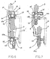
- the pump is schematically shown in sectioned view in Figures 6 , 9 and 10 as a whole body, since it is known per se. Obviously, the pump is provided with a connection for the fluid between the first outlet 15b and the third inlet 19a, and with known means for pushing the fluid in the desired direction.
- the first body 14 and the second body 18 are suitably arranged on different levels, the first body 14 corresponding to the level of the intake manifold 4 of the high-temperature circuit 2 and of the return manifold 12 of the low-temperature circuit 3, and the second body 18 corresponding to the level of the return manifold 5 of the high-temperature circuit 2 and of the intake manifold 11 of the low-temperature circuit 3.
- the first outlet 15b and the third inlet 19a are advantageously coplanar and therefore protrude from their respective bodies 14, 18, so as that the pump 22 can be easily mounted.
- the device 1 further comprises means 23 for varying the amount of water flowing from the second path 16 to the first path 15, which are operatively associated to the first body 14 on the re-circulation opening 17.
- Said means 23 are advantageously adjustable so as to vary the flow rate of the return low-temperature water to be mixed with the high-temperature water coming from the first inlet 15a, so as to send to the third path 19 of the second body 18 and to the intake manifold 11 of the low-temperature circuit 3 water suitably pre-mixed according to heating needs.
- Said means 23 can for instance comprise a manually adjustable holder 23 so as to define the maximum potentiality of the low-temperature heating circuit 3.
- the device 1 further comprises means 24 for regulating the water flow through the first inlet 15a, which are associated to the first body 14 within the first path 15.
- Said flow-regulating means 24 comprise a thermostatic head 24a, operatively active so as to actuate a shutter 24b placed in the first path 15 so as to vary the flow of high-temperature water entering the device 1.
- Said regulating means further comprise a sensor 24c placed within the third path 19 and operatively connected to the thermostatic head 14a, which can suitably regulate the amount of high-temperature hot water which is introduced into the device 1 and therefore into the low-temperature circuit 3 according to the temperature detected in the pre-mixed water entering the low-temperature circuit 3.
- said flow-regulating means 24 can comprise an electric motor provided with suitable sensors and operatively active so as to actuate a holder arranged within the first path 15 so as to vary the flow of intake high-temperature water.
- the device 1 can further comprise means for controlling the working of the device 1 (not shown in the figures because of their conventional shape), operatively connected to the means 24 for regulating the intake flow.
- Such means can be conventional electromechanical or electronic control systems and can be connected to suitable means for controlling the working of the general heating system.
- the device 1 further comprises a bypass duct 25, as can be seen in Figures 5 and 7 , connecting the second path 16 and the third path 19, which houses a bypass valve 26 allowing water to flow from the third to the second path 16 when water pressure in the device 1 is above a pre-established value.
- a bypass duct 25 enables for instance to prevent the system and the pump from being damaged in case the circulation of water within the low-temperature circuit 3 should be prevented, for instance due to the temporary shutting of all regulating heads 13a for the various heating elements 13.
- it can be provided for a stop of the pump 22 controlled by a global control system of the device 1.
- the device 1 further comprises a safety thermostatic switch (not shown in the figures) operatively connected to said device 1 and in particular to the flow-regulating means 24 so as to stop the flow of high-temperature water in the first inlet 15a when the temperature within the third path 19 is above a pre-established threshold level, for instance 50 degrees centigrade.
- a safety thermostatic switch is a further safety device against the damage of the low-temperature circuit 3 and of the structures in contact with the latter.
- the device 1 is further provided with thermometers 27 placed in some water paths so as to indicate water temperature in the concerned path.
- the device 1 further comprises an adjustable closing element 28, for instance a holder or a ball valve, so as to block the flow of fluid in the device 1, and an outlet tap 8 so as to empty the device 1.
- stopping elements are provided on the first outlet 15b and on the third inlet 19a, so as to insulate the pump 22, and on the fourth outlet 20b.
- the device 1 further comprises some automatic relief valves 9 expelling air bubbles that might form in
- the heating system is further equipped with known means for controlling the working of said system, which comprise a system for regulating temperature in the room, either with manual or automatic control and controlling the intake of high-temperature water into the device 1 when room temperature detected in the room is bellow a pre-established value.
- the working of a regulating device for heating system according to the present invention is the following.
- the adjustable holder 23 on the re-circulation opening 17 is adjusted while installing the device 1, so as to obtain the maximum potentiality of the low-temperature heating circuit 3.
- the thermostatic head 24a automatically regulates on the basis of the temperatures detected by the sensor 24c placed in the third path 19, the flow of high-temperature water, which is introduced into the device 1 and mixed with a given amount of low-temperature return water in the second path 16.
- Such mixed water then goes out of the first outlet 15b and is pushed by the pump 22 through the third path 19 of the second body 18, and then into the intake manifold 11 of the low-temperature circuit 3.
- the water coming back from the low-temperature circuit 3 gets into the second inlet 16a and is partly sent through the re-circulation opening 17 and partly gets out of the second outlet 16b and reaches the fourth path 20 of the second body 18, from where it is re-introduced into the high-temperature circuit 2 through the fourth outlet 20b.
- these are closed circuits given a certain flow of high-temperature water entering the device 1, there is a corresponding flow of low-temperature water getting out of the second outlet 16b and then from the fourth outlet 20b.
- the thermostatic head 24a wholly closes the first inlet 15a, all low-temperature water is recirculated in the low-temperature circuit 3.
- Reference values for water operating temperatures in the various parts of the device 1 can be for instance the following: in the first inlet 15a water is at about 70-80°C, in the first outlet 15b, after pre-mixing, at about 40-42°C, as in the third outlet 19b and therefore in the low-temperature intake manifold 11, whereas in the second inlet 16a and in the low-temperature return manifold 12 water is at about 30-32°C.
- a regulating device for heating systems according to the invention has a highly simple and rational structure. Moreover, it should be pointed out that such regulating device has a very small size and a global compact structure. Furthermore, the invention can be easily carried out and rapidly and easily installed. A device according to the invention is further reliable and efficient and ensures a high operating safety. Said device enables an optimal regulation of temperature both in single domestic systems and in central heating systems. Finally, it should be noted that a regulating device according to the present invention has extremely low manufacturing, installation and maintenance costs.
Landscapes
- Engineering & Computer Science (AREA)
- Physics & Mathematics (AREA)
- Thermal Sciences (AREA)
- Chemical & Material Sciences (AREA)
- Combustion & Propulsion (AREA)
- Mechanical Engineering (AREA)
- General Engineering & Computer Science (AREA)
- Steam Or Hot-Water Central Heating Systems (AREA)
Claims (23)
- Dispositif de régulation (1) pour systèmes de chauffage comprenant :un premier corps (14) définissant un premier passage (15) pour un liquide, qui s'étend depuis un premier orifice d'entrée (15a) jusqu'à un premier orifice de sortie (15b), et un second passage (16) pour le liquide s'étendant depuis un second orifice d'entrée (16a) jusqu'à un second orifice de sortie (16b) ;un second corps (18) définissant un troisième passage (19) pour le liquide, qui s'étend depuis un troisième orifice d'entrée (19a), fonctionnellement connecté audit premier orifice de sortie (15b), jusqu'à un troisième orifice de sortie (19b) ; etune pompe (22) pour la circulation du liquide, qui est fonctionnellement disposée entre ledit premier orifice de sortie (15b) et ledit troisième orifice d'entrée (19a) ;ledit premier corps (14) étant mis en oeuvre en une seule pièce et ledit premier passage (15) étant fonctionnellement connecté audit second passage (16) à l'aide d'une ouverture de re-circulation (17) afin de mélanger une quantité préétablie du liquide s'écoulant dans le second passage (16) au liquide s'écoulant dans le premier passage (15) ;le dispositif (1) comprenant en outre des moyens (23) de faire varier la quantité de liquide s'écoulant depuis ledit second passage (16) vers ledit premier passage (15), qui sont fonctionnellement associés au premier corps (14) sur ladite ouverture de re-circulation (17) etdes moyens (24) de régulation de l'écoulement du liquide à travers ledit premier orifice d'entrée (15a), qui sont associés audit premier corps (14) dans ledit premier passage (15).
- Dispositif selon la revendication 1, caractérisé en ce que ledit second orifice de sortie (16b) est placé entre ledit second orifice d'entrée (16a) et ladite ouverture de re-circulation (17).
- Dispositif selon les revendications 1 ou 2, caractérisé en ce que ledit premier orifice d'entrée (15a) et ledit second orifice de sortie (16b) peuvent être fonctionnellement connectés à un chauffe-eau ou à un circuit de chauffage (2) avec de l'eau à haute température, et en ce que ledit second orifice d'entrée (16a) et ledit troisième orifice de sortie (19b) peuvent être fonctionnellement connectés à un circuit de chauffage (3) avec de l'eau à basse température.
- Dispositif selon la revendication 3, caractérisé en ce que ledit second corps (18) définit en outre un quatrième passage (20) pour le liquide s'étendant depuis un quatrième orifice d'entrée (20a), fonctionnellement connecté audit second orifice de sortie (16b), à un quatrième orifice de sortie (20b) pouvant être fonctionnellement connecté au chauffe-eau ou au circuit de chauffage (2) avec de l'eau à haute température.
- Dispositif selon la revendication 4, caractérisé en ce que le quatrième orifice d'entrée (20a) est connecté au second orifice de sortie (16b) à l'aide d'un conduit de connexion (21).
- Dispositif selon l'une quelconque des revendications précédentes, caractérisé en ce que ledit second corps (18) est mis en oeuvre en une seule pièce.
- Dispositif selon l'une quelconque des revendications 1 à 5, caractérisé en ce que ledit second corps (18) est constitué de plusieurs parties montées ensemble.
- Dispositif selon l'une quelconque des revendications précédentes, caractérisé en ce que lesdits moyens de variation (23) comprennent un dispositif de maintien ajustable.
- Dispositif selon l'une quelconque des revendications précédentes, caractérisé en ce que ledit premier corps (14) et/ou ledit second corps (18) sont mis en oeuvre par métal coulé.
- Dispositif selon l'une quelconque des revendications précédentes, caractérisé en ce que ledit premier orifice de sortie (15b) et ledit troisième orifice d'entrée (19a) sont coplanaires et font respectivement saillie depuis le premier et le second corps.
- Dispositif selon l'une quelconque des revendications précédentes, caractérisé en ce que ledit premier orifice d'entrée (15a) et ledit second orifice d'entrée (16a) sont placés dans des positions opposées par rapport au premier corps (14) et sont substantiellement alignés.
- Dispositif selon la revendication 11, caractérisé en ce que ledit premier orifice de sortie (15b) présente un axe longitudinal substantiellement perpendiculaire aux axes dudit premier orifice d'entrée (15a) et dudit second orifice d'entrée (16a).
- Dispositif selon l'une quelconque des revendications 4 à 12, caractérisé en ce que ledit troisième orifice de sortie (19b) et ledit quatrième orifice de sortie (20b) sont placés dans des positions opposées par rapport au second corps (18) et sont substantiellement alignés.
- Dispositif selon la revendication 13, caractérisé en ce que ledit troisième orifice d'entrée (19a) présente un axe longitudinal substantiellement perpendiculaire aux axes dudit troisième (19b) et dudit quatrième orifices de sortie (20b).
- Dispositif selon l'une quelconque des revendications précédentes, caractérisé en ce que lesdits moyens de régulation d'écoulement (24) comprennent une tête thermostatique (24a) fonctionnellement active afin d'actionner un obturateur (24b) placé dans le premier passage (15) afin de faire varier l'écoulement du liquide d'entrée, et un détecteur (24c) placé dans ledit troisième passage (19) et fonctionnellement connecté à ladite tête thermostatique (24a).
- Dispositif selon l'une quelconque des revendications 1 à 14, caractérisé en ce que lesdits moyens de régulation d'écoulement (24) comprennent un moteur électrique fonctionnellement actif afin d'actionner un dispositif de maintien placé dans le premier passage (15) afin de faire varier l'écoulement du liquide d'entrée.
- Dispositif selon l'une quelconque des revendications précédentes, caractérisé en ce qu'il comprend des moyens de contrôle du fonctionnement du dispositif (1) fonctionnellement connecté auxdits moyens de régulation d'écoulement (24).
- Dispositif selon l'une quelconque des revendications précédentes, caractérisé en ce qu'il comprend en outre une conduite de dérivation (25) connectant ledit second passage (16) et ledit troisième passage (19), et une vanne de dérivation (26) placée dans la conduite de dérivation (25) afin de permettre l'écoulement du liquide depuis le troisième (19) vers le second passage (16) lorsque la pression du liquide dans le dispositif (1) est située au-dessus d'une valeur préétablie.
- Dispositif selon l'une quelconque des revendications précédentes, caractérisé en ce qu'il comprend en outre un commutateur thermostatique de sécurité fonctionnellement connecté au dispositif (1) afin de bloquer l'écoulement du liquide dans le premier orifice d'entrée (15a) lorsque la température dans le troisième passage (19) est située au-dessus d'une valeur seuil préétablie.
- Dispositif selon l'une quelconque des revendications précédentes, caractérisé en ce qu'il comprend en outre un thermomètre (27) placé dans l'un desdits passages de liquide afin d'indiquer la température du liquide dans son passage respectif.
- Dispositif selon l'une quelconque des revendications précédentes, caractérisé en ce qu'il comprend en outre un élément de fermeture ajustable (28) pour bloquer l'écoulement du liquide dans le dispositif, et un robinet d'orifice de sortie (8) pour vider le dispositif (1).
- Dispositif selon l'une quelconque des revendications précédentes, caractérisé en ce qu'il comprend en outre un clapet de sécurité pneumatique automatique (9).
- Système de chauffage de pièces caractérisé en ce qu'il comprend un dispositif (1) selon l'une quelconque des revendications précédentes.
Applications Claiming Priority (1)
| Application Number | Priority Date | Filing Date | Title |
|---|---|---|---|
| PCT/IT2003/000054 WO2004070280A1 (fr) | 2003-02-04 | 2003-02-04 | Dispositif de regulation pour installation de chauffage |
Publications (2)
| Publication Number | Publication Date |
|---|---|
| EP1590607A1 EP1590607A1 (fr) | 2005-11-02 |
| EP1590607B1 true EP1590607B1 (fr) | 2016-09-14 |
Family
ID=32843860
Family Applications (1)
| Application Number | Title | Priority Date | Filing Date |
|---|---|---|---|
| EP03815723.6A Expired - Lifetime EP1590607B1 (fr) | 2003-02-04 | 2003-02-04 | Dispositif de régulation pour installation de chauffage |
Country Status (7)
| Country | Link |
|---|---|
| EP (1) | EP1590607B1 (fr) |
| CN (1) | CN100441961C (fr) |
| AU (1) | AU2003215889A1 (fr) |
| ES (1) | ES2606777T3 (fr) |
| HU (1) | HUE030743T2 (fr) |
| PT (1) | PT1590607T (fr) |
| WO (1) | WO2004070280A1 (fr) |
Families Citing this family (5)
| Publication number | Priority date | Publication date | Assignee | Title |
|---|---|---|---|---|
| CN102016739B (zh) * | 2008-04-23 | 2013-04-24 | I.V.A.R.股份公司 | 用于朝向使用者供给和控制水流的液压装置 |
| IT1396314B1 (it) * | 2009-09-29 | 2012-11-16 | Trezeta Srl | Struttura di modulo di distribuzione perfezionato, particolarmente per la distribuzione di acqua di riscaldamento o raffrescamento. |
| ITMI20100077U1 (it) * | 2010-03-19 | 2011-09-20 | Ivar Spa | Dispositivo per la distribuzione di acqua di riscaldamento |
| DK2871420T3 (en) * | 2013-11-07 | 2016-12-19 | Grundfos Holding As | Cirkulationspumpeaggregat to a heating and / or cooling system |
| ITBS20140015U1 (it) * | 2014-09-23 | 2016-03-23 | Ivar Spa | Dispositivo di regolazione per impianti termici |
Family Cites Families (4)
| Publication number | Priority date | Publication date | Assignee | Title |
|---|---|---|---|---|
| NL6708548A (fr) * | 1966-06-28 | 1967-12-29 | ||
| FR2740863B3 (fr) * | 1995-11-08 | 1998-02-20 | Axterm | Dispositif d'alimentation a partir d'une meme chaudiere de deux circuits d'eau chaude a des temperatures differentes |
| DE29820945U1 (de) * | 1998-11-17 | 1999-04-22 | Schöttler, Frank, 14089 Berlin | Einrichtung zur Regelung der Vorlauftemperatur (bei Warmwasser-Fußbodenheizungen) für kombinierte Fußbodenheizungs- und Heizkörperanlagen |
| IT1309348B1 (it) * | 1999-03-02 | 2002-01-22 | Luigi Castelletti | Collettore modulare provvisto di sistema di termoregolazione, perimpianti di riscaldamento a pannelli radianti o simili. |
-
2003
- 2003-02-04 ES ES03815723.6T patent/ES2606777T3/es not_active Expired - Lifetime
- 2003-02-04 WO PCT/IT2003/000054 patent/WO2004070280A1/fr not_active Ceased
- 2003-02-04 HU HUE03815723A patent/HUE030743T2/en unknown
- 2003-02-04 CN CNB038259117A patent/CN100441961C/zh not_active Expired - Fee Related
- 2003-02-04 PT PT38157236T patent/PT1590607T/pt unknown
- 2003-02-04 AU AU2003215889A patent/AU2003215889A1/en not_active Abandoned
- 2003-02-04 EP EP03815723.6A patent/EP1590607B1/fr not_active Expired - Lifetime
Also Published As
| Publication number | Publication date |
|---|---|
| PT1590607T (pt) | 2016-12-14 |
| WO2004070280A1 (fr) | 2004-08-19 |
| AU2003215889A1 (en) | 2004-08-30 |
| EP1590607A1 (fr) | 2005-11-02 |
| CN1738994A (zh) | 2006-02-22 |
| CN100441961C (zh) | 2008-12-10 |
| HUE030743T2 (en) | 2017-05-29 |
| ES2606777T3 (es) | 2017-03-27 |
Similar Documents
| Publication | Publication Date | Title |
|---|---|---|
| EP2672190B1 (fr) | Unité de conditionnement d'air ambiant à usage résidentiel | |
| CN105705867A (zh) | 用于液压供热和/或冷却系统的液压分配器 | |
| US20090178717A1 (en) | Mixing and pumping system for use with installed hydronic radiant floor heating systems and the like | |
| CN113124559A (zh) | 一种便于洗浴和采暖同时运行的壁挂炉控制系统 | |
| EP1590607B1 (fr) | Dispositif de régulation pour installation de chauffage | |
| CA3054111C (fr) | Procede et dispositif pour economiser l'energie calorifique et l'eau dans une installation sanitaire | |
| IT202100011261A1 (it) | Impianto di condizionamento e/o riscaldamento e processo di controllo di detto impianto | |
| US20080156281A1 (en) | Heating Control System | |
| KR19980018617A (ko) | 온수·위생수겸용설비용 수압식 어셈블리 | |
| KR200484019Y1 (ko) | 난방용 온수 분배장치 | |
| CN210425217U (zh) | 一种蓄能装置 | |
| KR200263677Y1 (ko) | 온수분배 시스템 | |
| ITTO20070012A1 (it) | Unita di distribuzione di fluidi, e metodo per distribuire fluidi. | |
| EP0048517A1 (fr) | Système de chauffage urbain ou de chauffage de groupes d'immeubles | |
| US20040104281A1 (en) | Fitting-assembly and fitting-block for a central heating system | |
| CN110397978B (zh) | 一种蓄能装置及其控制方法 | |
| KR200482921Y1 (ko) | 난방용 온수 분배장치 | |
| JP4822051B2 (ja) | ミスト発生装置及びこれを備えたミスト機能付き浴室乾燥機 | |
| RU2188359C1 (ru) | Квартирная система отопления | |
| EP0048518A1 (fr) | Système de chauffage urbain ou de chauffage de groupes d'immeubles | |
| KR101876515B1 (ko) | 난방수 순환 제어 시스템 및 이를 이용한 난방수 공급방법 | |
| KR20180000640U (ko) | 바이패스관을 갖는 온수 분배장치 | |
| CN224080276U (zh) | 一种混水装置及供暖系统 | |
| RU2487302C2 (ru) | Система управления приточной вентиляционной установкой с переключателем на режим экономичного теплопотребления | |
| EA030320B1 (ru) | Регулирующее устройство для систем отопления |
Legal Events
| Date | Code | Title | Description |
|---|---|---|---|
| PUAI | Public reference made under article 153(3) epc to a published international application that has entered the european phase |
Free format text: ORIGINAL CODE: 0009012 |
|
| 17P | Request for examination filed |
Effective date: 20050701 |
|
| AK | Designated contracting states |
Kind code of ref document: A1 Designated state(s): AT BE BG CH CY CZ DE DK EE ES FI FR GB GR HU IE IT LI LU MC NL PT SE SI SK TR |
|
| AX | Request for extension of the european patent |
Extension state: AL LT LV MK RO |
|
| RAX | Requested extension states of the european patent have changed |
Extension state: LV Payment date: 20050701 Extension state: AL Payment date: 20050701 |
|
| 17Q | First examination report despatched |
Effective date: 20060822 |
|
| GRAP | Despatch of communication of intention to grant a patent |
Free format text: ORIGINAL CODE: EPIDOSNIGR1 |
|
| INTG | Intention to grant announced |
Effective date: 20160509 |
|
| GRAS | Grant fee paid |
Free format text: ORIGINAL CODE: EPIDOSNIGR3 |
|
| GRAA | (expected) grant |
Free format text: ORIGINAL CODE: 0009210 |
|
| AK | Designated contracting states |
Kind code of ref document: B1 Designated state(s): AT BE BG CH CY CZ DE DK EE ES FI FR GB GR HU IE IT LI LU MC NL PT SE SI SK TR |
|
| AX | Request for extension of the european patent |
Extension state: AL LV |
|
| REG | Reference to a national code |
Ref country code: GB Ref legal event code: FG4D |
|
| REG | Reference to a national code |
Ref country code: CH Ref legal event code: EP |
|
| REG | Reference to a national code |
Ref country code: IE Ref legal event code: FG4D |
|
| REG | Reference to a national code |
Ref country code: AT Ref legal event code: REF Ref document number: 829438 Country of ref document: AT Kind code of ref document: T Effective date: 20161015 |
|
| REG | Reference to a national code |
Ref country code: DE Ref legal event code: R096 Ref document number: 60349399 Country of ref document: DE |
|
| REG | Reference to a national code |
Ref country code: CH Ref legal event code: NV Representative=s name: ING. ALESSANDRO GALASSI C/O PGA SRL, MILANO, S, CH |
|
| REG | Reference to a national code |
Ref country code: NL Ref legal event code: FP Ref country code: PT Ref legal event code: SC4A Ref document number: 1590607 Country of ref document: PT Date of ref document: 20161214 Kind code of ref document: T Free format text: AVAILABILITY OF NATIONAL TRANSLATION Effective date: 20161206 |
|
| REG | Reference to a national code |
Ref country code: SE Ref legal event code: TRGR |
|
| REG | Reference to a national code |
Ref country code: FR Ref legal event code: PLFP Year of fee payment: 15 |
|
| REG | Reference to a national code |
Ref country code: EE Ref legal event code: FG4A Ref document number: E013045 Country of ref document: EE Effective date: 20161206 |
|
| REG | Reference to a national code |
Ref country code: HU Ref legal event code: AG4A Ref document number: E030743 Country of ref document: HU |
|
| PG25 | Lapsed in a contracting state [announced via postgrant information from national office to epo] |
Ref country code: BG Free format text: LAPSE BECAUSE OF FAILURE TO SUBMIT A TRANSLATION OF THE DESCRIPTION OR TO PAY THE FEE WITHIN THE PRESCRIBED TIME-LIMIT Effective date: 20161214 |
|
| REG | Reference to a national code |
Ref country code: SK Ref legal event code: T3 Ref document number: E 22868 Country of ref document: SK |
|
| REG | Reference to a national code |
Ref country code: DE Ref legal event code: R097 Ref document number: 60349399 Country of ref document: DE |
|
| REG | Reference to a national code |
Ref country code: GR Ref legal event code: EP Ref document number: 20160403024 Country of ref document: GR Effective date: 20170410 |
|
| PLBE | No opposition filed within time limit |
Free format text: ORIGINAL CODE: 0009261 |
|
| STAA | Information on the status of an ep patent application or granted ep patent |
Free format text: STATUS: NO OPPOSITION FILED WITHIN TIME LIMIT |
|
| PG25 | Lapsed in a contracting state [announced via postgrant information from national office to epo] |
Ref country code: DK Free format text: LAPSE BECAUSE OF FAILURE TO SUBMIT A TRANSLATION OF THE DESCRIPTION OR TO PAY THE FEE WITHIN THE PRESCRIBED TIME-LIMIT Effective date: 20160914 |
|
| 26N | No opposition filed |
Effective date: 20170615 |
|
| PG25 | Lapsed in a contracting state [announced via postgrant information from national office to epo] |
Ref country code: MC Free format text: LAPSE BECAUSE OF FAILURE TO SUBMIT A TRANSLATION OF THE DESCRIPTION OR TO PAY THE FEE WITHIN THE PRESCRIBED TIME-LIMIT Effective date: 20160914 |
|
| REG | Reference to a national code |
Ref country code: FR Ref legal event code: PLFP Year of fee payment: 16 |
|
| PG25 | Lapsed in a contracting state [announced via postgrant information from national office to epo] |
Ref country code: LU Free format text: LAPSE BECAUSE OF NON-PAYMENT OF DUE FEES Effective date: 20170204 |
|
| PGFP | Annual fee paid to national office [announced via postgrant information from national office to epo] |
Ref country code: FR Payment date: 20171221 Year of fee payment: 16 |
|
| PGFP | Annual fee paid to national office [announced via postgrant information from national office to epo] |
Ref country code: NL Payment date: 20180115 Year of fee payment: 16 |
|
| PGFP | Annual fee paid to national office [announced via postgrant information from national office to epo] |
Ref country code: GB Payment date: 20180103 Year of fee payment: 16 Ref country code: FI Payment date: 20180209 Year of fee payment: 16 Ref country code: CH Payment date: 20180213 Year of fee payment: 16 |
|
| PGFP | Annual fee paid to national office [announced via postgrant information from national office to epo] |
Ref country code: PT Payment date: 20180202 Year of fee payment: 16 Ref country code: GR Payment date: 20180116 Year of fee payment: 16 Ref country code: SE Payment date: 20180213 Year of fee payment: 16 Ref country code: EE Payment date: 20180126 Year of fee payment: 16 Ref country code: HU Payment date: 20180108 Year of fee payment: 16 Ref country code: AT Payment date: 20180125 Year of fee payment: 16 Ref country code: SI Payment date: 20180110 Year of fee payment: 16 |
|
| REG | Reference to a national code |
Ref country code: IE Ref legal event code: MM4A |
|
| PG25 | Lapsed in a contracting state [announced via postgrant information from national office to epo] |
Ref country code: IE Free format text: LAPSE BECAUSE OF NON-PAYMENT OF DUE FEES Effective date: 20170204 |
|
| REG | Reference to a national code |
Ref country code: AT Ref legal event code: UEP Ref document number: 829438 Country of ref document: AT Kind code of ref document: T Effective date: 20160914 |
|
| REG | Reference to a national code |
Ref country code: EE Ref legal event code: MM4A Ref document number: E013045 Country of ref document: EE Effective date: 20190228 |
|
| REG | Reference to a national code |
Ref country code: CH Ref legal event code: PL |
|
| REG | Reference to a national code |
Ref country code: SE Ref legal event code: EUG |
|
| REG | Reference to a national code |
Ref country code: NL Ref legal event code: MM Effective date: 20190301 |
|
| REG | Reference to a national code |
Ref country code: AT Ref legal event code: MM01 Ref document number: 829438 Country of ref document: AT Kind code of ref document: T Effective date: 20190204 |
|
| GBPC | Gb: european patent ceased through non-payment of renewal fee |
Effective date: 20190204 |
|
| REG | Reference to a national code |
Ref country code: SI Ref legal event code: KO00 Effective date: 20190927 |
|
| PG25 | Lapsed in a contracting state [announced via postgrant information from national office to epo] |
Ref country code: SI Free format text: LAPSE BECAUSE OF NON-PAYMENT OF DUE FEES Effective date: 20190205 Ref country code: EE Free format text: LAPSE BECAUSE OF NON-PAYMENT OF DUE FEES Effective date: 20190228 Ref country code: SE Free format text: LAPSE BECAUSE OF NON-PAYMENT OF DUE FEES Effective date: 20190205 Ref country code: CY Free format text: LAPSE BECAUSE OF NON-PAYMENT OF DUE FEES Effective date: 20160914 Ref country code: FI Free format text: LAPSE BECAUSE OF NON-PAYMENT OF DUE FEES Effective date: 20190204 Ref country code: PT Free format text: LAPSE BECAUSE OF NON-PAYMENT OF DUE FEES Effective date: 20190805 |
|
| PG25 | Lapsed in a contracting state [announced via postgrant information from national office to epo] |
Ref country code: GR Free format text: LAPSE BECAUSE OF NON-PAYMENT OF DUE FEES Effective date: 20190904 Ref country code: HU Free format text: LAPSE BECAUSE OF NON-PAYMENT OF DUE FEES Effective date: 20190205 |
|
| PG25 | Lapsed in a contracting state [announced via postgrant information from national office to epo] |
Ref country code: CH Free format text: LAPSE BECAUSE OF NON-PAYMENT OF DUE FEES Effective date: 20190228 Ref country code: AT Free format text: LAPSE BECAUSE OF NON-PAYMENT OF DUE FEES Effective date: 20190204 Ref country code: LI Free format text: LAPSE BECAUSE OF NON-PAYMENT OF DUE FEES Effective date: 20190228 |
|
| PG25 | Lapsed in a contracting state [announced via postgrant information from national office to epo] |
Ref country code: GB Free format text: LAPSE BECAUSE OF NON-PAYMENT OF DUE FEES Effective date: 20190204 Ref country code: NL Free format text: LAPSE BECAUSE OF NON-PAYMENT OF DUE FEES Effective date: 20190301 |
|
| PG25 | Lapsed in a contracting state [announced via postgrant information from national office to epo] |
Ref country code: FR Free format text: LAPSE BECAUSE OF NON-PAYMENT OF DUE FEES Effective date: 20190228 |
|
| PGFP | Annual fee paid to national office [announced via postgrant information from national office to epo] |
Ref country code: DE Payment date: 20200228 Year of fee payment: 18 Ref country code: IT Payment date: 20200221 Year of fee payment: 18 Ref country code: ES Payment date: 20200323 Year of fee payment: 18 |
|
| PGFP | Annual fee paid to national office [announced via postgrant information from national office to epo] |
Ref country code: CZ Payment date: 20200130 Year of fee payment: 18 Ref country code: SK Payment date: 20200115 Year of fee payment: 18 Ref country code: BE Payment date: 20200225 Year of fee payment: 18 |
|
| PGFP | Annual fee paid to national office [announced via postgrant information from national office to epo] |
Ref country code: TR Payment date: 20200130 Year of fee payment: 18 |
|
| REG | Reference to a national code |
Ref country code: DE Ref legal event code: R119 Ref document number: 60349399 Country of ref document: DE |
|
| REG | Reference to a national code |
Ref country code: BE Ref legal event code: MM Effective date: 20210228 Ref country code: SK Ref legal event code: MM4A Ref document number: E 22868 Country of ref document: SK Effective date: 20210204 |
|
| PG25 | Lapsed in a contracting state [announced via postgrant information from national office to epo] |
Ref country code: CZ Free format text: LAPSE BECAUSE OF NON-PAYMENT OF DUE FEES Effective date: 20210204 |
|
| PG25 | Lapsed in a contracting state [announced via postgrant information from national office to epo] |
Ref country code: SK Free format text: LAPSE BECAUSE OF NON-PAYMENT OF DUE FEES Effective date: 20210204 |
|
| PG25 | Lapsed in a contracting state [announced via postgrant information from national office to epo] |
Ref country code: DE Free format text: LAPSE BECAUSE OF NON-PAYMENT OF DUE FEES Effective date: 20210901 |
|
| PG25 | Lapsed in a contracting state [announced via postgrant information from national office to epo] |
Ref country code: IT Free format text: LAPSE BECAUSE OF NON-PAYMENT OF DUE FEES Effective date: 20210204 |
|
| REG | Reference to a national code |
Ref country code: ES Ref legal event code: FD2A Effective date: 20220510 |
|
| PG25 | Lapsed in a contracting state [announced via postgrant information from national office to epo] |
Ref country code: ES Free format text: LAPSE BECAUSE OF NON-PAYMENT OF DUE FEES Effective date: 20210205 Ref country code: BE Free format text: LAPSE BECAUSE OF NON-PAYMENT OF DUE FEES Effective date: 20210228 |
|
| PG25 | Lapsed in a contracting state [announced via postgrant information from national office to epo] |
Ref country code: TR Free format text: LAPSE BECAUSE OF NON-PAYMENT OF DUE FEES Effective date: 20210204 |