EP1590621B1 - Warmetauscher eines belüftungssystems - Google Patents
Warmetauscher eines belüftungssystems Download PDFInfo
- Publication number
- EP1590621B1 EP1590621B1 EP03703497A EP03703497A EP1590621B1 EP 1590621 B1 EP1590621 B1 EP 1590621B1 EP 03703497 A EP03703497 A EP 03703497A EP 03703497 A EP03703497 A EP 03703497A EP 1590621 B1 EP1590621 B1 EP 1590621B1
- Authority
- EP
- European Patent Office
- Prior art keywords
- heat exchanger
- air
- corrugation
- plates
- building
- Prior art date
- Legal status (The legal status is an assumption and is not a legal conclusion. Google has not performed a legal analysis and makes no representation as to the accuracy of the status listed.)
- Expired - Lifetime
Links
- 239000000463 material Substances 0.000 claims abstract description 38
- 238000004140 cleaning Methods 0.000 claims abstract description 10
- 239000003610 charcoal Substances 0.000 claims description 21
- 229910052799 carbon Inorganic materials 0.000 claims description 19
- OKTJSMMVPCPJKN-UHFFFAOYSA-N Carbon Chemical compound [C] OKTJSMMVPCPJKN-UHFFFAOYSA-N 0.000 claims description 18
- 239000000835 fiber Substances 0.000 claims description 12
- 150000002500 ions Chemical class 0.000 claims description 9
- 235000008733 Citrus aurantifolia Nutrition 0.000 claims description 7
- 235000011941 Tilia x europaea Nutrition 0.000 claims description 7
- XAGFODPZIPBFFR-UHFFFAOYSA-N aluminium Chemical compound [Al] XAGFODPZIPBFFR-UHFFFAOYSA-N 0.000 claims description 7
- 229910052782 aluminium Inorganic materials 0.000 claims description 7
- 239000004571 lime Substances 0.000 claims description 7
- XEEYBQQBJWHFJM-UHFFFAOYSA-N Iron Chemical compound [Fe] XEEYBQQBJWHFJM-UHFFFAOYSA-N 0.000 claims description 6
- NBIIXXVUZAFLBC-UHFFFAOYSA-N Phosphoric acid Chemical compound OP(O)(O)=O NBIIXXVUZAFLBC-UHFFFAOYSA-N 0.000 claims description 6
- BWHMMNNQKKPAPP-UHFFFAOYSA-L potassium carbonate Chemical compound [K+].[K+].[O-]C([O-])=O BWHMMNNQKKPAPP-UHFFFAOYSA-L 0.000 claims description 6
- 239000002023 wood Substances 0.000 claims description 6
- JIAARYAFYJHUJI-UHFFFAOYSA-L zinc dichloride Chemical compound [Cl-].[Cl-].[Zn+2] JIAARYAFYJHUJI-UHFFFAOYSA-L 0.000 claims description 6
- 239000001913 cellulose Substances 0.000 claims description 5
- 229920002678 cellulose Polymers 0.000 claims description 5
- VYPSYNLAJGMNEJ-UHFFFAOYSA-N Silicium dioxide Chemical compound O=[Si]=O VYPSYNLAJGMNEJ-UHFFFAOYSA-N 0.000 claims description 4
- PNEYBMLMFCGWSK-UHFFFAOYSA-N aluminium oxide Inorganic materials [O-2].[O-2].[O-2].[Al+3].[Al+3] PNEYBMLMFCGWSK-UHFFFAOYSA-N 0.000 claims description 4
- 238000001035 drying Methods 0.000 claims description 4
- 229920005610 lignin Polymers 0.000 claims description 4
- 239000000126 substance Substances 0.000 claims description 4
- FYYHWMGAXLPEAU-UHFFFAOYSA-N Magnesium Chemical compound [Mg] FYYHWMGAXLPEAU-UHFFFAOYSA-N 0.000 claims description 3
- 230000003213 activating effect Effects 0.000 claims description 3
- 230000004913 activation Effects 0.000 claims description 3
- 229910000147 aluminium phosphate Inorganic materials 0.000 claims description 3
- 238000010000 carbonizing Methods 0.000 claims description 3
- 239000003795 chemical substances by application Substances 0.000 claims description 3
- 229910052742 iron Inorganic materials 0.000 claims description 3
- 239000003077 lignite Substances 0.000 claims description 3
- 239000011777 magnesium Substances 0.000 claims description 3
- 229910052749 magnesium Inorganic materials 0.000 claims description 3
- 239000002245 particle Substances 0.000 claims description 3
- 229910000027 potassium carbonate Inorganic materials 0.000 claims description 3
- 239000011592 zinc chloride Substances 0.000 claims description 3
- 235000005074 zinc chloride Nutrition 0.000 claims description 3
- 240000006248 Broussonetia kazinoki Species 0.000 claims 1
- 229910052593 corundum Inorganic materials 0.000 claims 1
- 229910001845 yogo sapphire Inorganic materials 0.000 claims 1
- 238000002156 mixing Methods 0.000 description 10
- 241000933832 Broussonetia Species 0.000 description 6
- 230000008859 change Effects 0.000 description 6
- 238000010276 construction Methods 0.000 description 6
- 230000008901 benefit Effects 0.000 description 5
- 238000007599 discharging Methods 0.000 description 5
- 238000000034 method Methods 0.000 description 5
- 238000010521 absorption reaction Methods 0.000 description 4
- 238000004519 manufacturing process Methods 0.000 description 4
- 238000000746 purification Methods 0.000 description 4
- HEMHJVSKTPXQMS-UHFFFAOYSA-M Sodium hydroxide Chemical compound [OH-].[Na+] HEMHJVSKTPXQMS-UHFFFAOYSA-M 0.000 description 3
- 230000003115 biocidal effect Effects 0.000 description 3
- 230000008569 process Effects 0.000 description 3
- XLYOFNOQVPJJNP-UHFFFAOYSA-N water Substances O XLYOFNOQVPJJNP-UHFFFAOYSA-N 0.000 description 3
- 230000015572 biosynthetic process Effects 0.000 description 2
- 238000009835 boiling Methods 0.000 description 2
- 238000004332 deodorization Methods 0.000 description 2
- 229910052500 inorganic mineral Inorganic materials 0.000 description 2
- 239000011707 mineral Substances 0.000 description 2
- 235000010755 mineral Nutrition 0.000 description 2
- 238000012986 modification Methods 0.000 description 2
- 230000004048 modification Effects 0.000 description 2
- 239000002689 soil Substances 0.000 description 2
- BVKZGUZCCUSVTD-UHFFFAOYSA-L Carbonate Chemical compound [O-]C([O-])=O BVKZGUZCCUSVTD-UHFFFAOYSA-L 0.000 description 1
- 239000010433 feldspar Substances 0.000 description 1
- 238000001914 filtration Methods 0.000 description 1
- 239000012535 impurity Substances 0.000 description 1
- 239000007788 liquid Substances 0.000 description 1
- 239000002075 main ingredient Substances 0.000 description 1
- 238000005360 mashing Methods 0.000 description 1
- 239000010445 mica Substances 0.000 description 1
- 229910052618 mica group Inorganic materials 0.000 description 1
- 230000000149 penetrating effect Effects 0.000 description 1
- 238000003825 pressing Methods 0.000 description 1
- 239000010453 quartz Substances 0.000 description 1
- 230000005855 radiation Effects 0.000 description 1
- 238000002791 soaking Methods 0.000 description 1
- 235000011121 sodium hydroxide Nutrition 0.000 description 1
- 238000001179 sorption measurement Methods 0.000 description 1
- 230000001954 sterilising effect Effects 0.000 description 1
- 238000004659 sterilization and disinfection Methods 0.000 description 1
Images



Classifications
-
- F—MECHANICAL ENGINEERING; LIGHTING; HEATING; WEAPONS; BLASTING
- F24—HEATING; RANGES; VENTILATING
- F24F—AIR-CONDITIONING; AIR-HUMIDIFICATION; VENTILATION; USE OF AIR CURRENTS FOR SCREENING
- F24F12/00—Use of energy recovery systems in air conditioning, ventilation or screening
- F24F12/001—Use of energy recovery systems in air conditioning, ventilation or screening with heat-exchange between supplied and exhausted air
- F24F12/006—Use of energy recovery systems in air conditioning, ventilation or screening with heat-exchange between supplied and exhausted air using an air-to-air heat exchanger
-
- F—MECHANICAL ENGINEERING; LIGHTING; HEATING; WEAPONS; BLASTING
- F24—HEATING; RANGES; VENTILATING
- F24F—AIR-CONDITIONING; AIR-HUMIDIFICATION; VENTILATION; USE OF AIR CURRENTS FOR SCREENING
- F24F3/00—Air-conditioning systems in which conditioned primary air is supplied from one or more central stations to distributing units in the rooms or spaces where it may receive secondary treatment; Apparatus specially designed for such systems
- F24F3/12—Air-conditioning systems in which conditioned primary air is supplied from one or more central stations to distributing units in the rooms or spaces where it may receive secondary treatment; Apparatus specially designed for such systems characterised by the treatment of the air otherwise than by heating and cooling
- F24F3/14—Air-conditioning systems in which conditioned primary air is supplied from one or more central stations to distributing units in the rooms or spaces where it may receive secondary treatment; Apparatus specially designed for such systems characterised by the treatment of the air otherwise than by heating and cooling by humidification; by dehumidification
- F24F3/147—Air-conditioning systems in which conditioned primary air is supplied from one or more central stations to distributing units in the rooms or spaces where it may receive secondary treatment; Apparatus specially designed for such systems characterised by the treatment of the air otherwise than by heating and cooling by humidification; by dehumidification with both heat and humidity transfer between supplied and exhausted air
-
- F—MECHANICAL ENGINEERING; LIGHTING; HEATING; WEAPONS; BLASTING
- F28—HEAT EXCHANGE IN GENERAL
- F28D—HEAT-EXCHANGE APPARATUS, NOT PROVIDED FOR IN ANOTHER SUBCLASS, IN WHICH THE HEAT-EXCHANGE MEDIA DO NOT COME INTO DIRECT CONTACT
- F28D21/00—Heat-exchange apparatus not covered by any of the groups F28D1/00 - F28D20/00
- F28D21/0015—Heat and mass exchangers, e.g. with permeable walls
-
- F—MECHANICAL ENGINEERING; LIGHTING; HEATING; WEAPONS; BLASTING
- F28—HEAT EXCHANGE IN GENERAL
- F28D—HEAT-EXCHANGE APPARATUS, NOT PROVIDED FOR IN ANOTHER SUBCLASS, IN WHICH THE HEAT-EXCHANGE MEDIA DO NOT COME INTO DIRECT CONTACT
- F28D9/00—Heat-exchange apparatus having stationary plate-like or laminated conduit assemblies for both heat-exchange media, the media being in contact with different sides of a conduit wall
- F28D9/0062—Heat-exchange apparatus having stationary plate-like or laminated conduit assemblies for both heat-exchange media, the media being in contact with different sides of a conduit wall the conduits for one heat-exchange medium being formed by spaced plates with inserted elements
-
- F—MECHANICAL ENGINEERING; LIGHTING; HEATING; WEAPONS; BLASTING
- F28—HEAT EXCHANGE IN GENERAL
- F28F—DETAILS OF HEAT-EXCHANGE AND HEAT-TRANSFER APPARATUS, OF GENERAL APPLICATION
- F28F21/00—Constructions of heat-exchange apparatus characterised by the selection of particular materials
-
- F—MECHANICAL ENGINEERING; LIGHTING; HEATING; WEAPONS; BLASTING
- F28—HEAT EXCHANGE IN GENERAL
- F28F—DETAILS OF HEAT-EXCHANGE AND HEAT-TRANSFER APPARATUS, OF GENERAL APPLICATION
- F28F2255/00—Heat exchanger elements made of materials having special features or resulting from particular manufacturing processes
-
- Y—GENERAL TAGGING OF NEW TECHNOLOGICAL DEVELOPMENTS; GENERAL TAGGING OF CROSS-SECTIONAL TECHNOLOGIES SPANNING OVER SEVERAL SECTIONS OF THE IPC; TECHNICAL SUBJECTS COVERED BY FORMER USPC CROSS-REFERENCE ART COLLECTIONS [XRACs] AND DIGESTS
- Y02—TECHNOLOGIES OR APPLICATIONS FOR MITIGATION OR ADAPTATION AGAINST CLIMATE CHANGE
- Y02B—CLIMATE CHANGE MITIGATION TECHNOLOGIES RELATED TO BUILDINGS, e.g. HOUSING, HOUSE APPLIANCES OR RELATED END-USER APPLICATIONS
- Y02B30/00—Energy efficient heating, ventilation or air conditioning [HVAC]
- Y02B30/56—Heat recovery units
-
- Y—GENERAL TAGGING OF NEW TECHNOLOGICAL DEVELOPMENTS; GENERAL TAGGING OF CROSS-SECTIONAL TECHNOLOGIES SPANNING OVER SEVERAL SECTIONS OF THE IPC; TECHNICAL SUBJECTS COVERED BY FORMER USPC CROSS-REFERENCE ART COLLECTIONS [XRACs] AND DIGESTS
- Y10—TECHNICAL SUBJECTS COVERED BY FORMER USPC
- Y10S—TECHNICAL SUBJECTS COVERED BY FORMER USPC CROSS-REFERENCE ART COLLECTIONS [XRACs] AND DIGESTS
- Y10S165/00—Heat exchange
- Y10S165/905—Materials of manufacture
Definitions
- the present invention relates to a heat exchanger for exchanging indoor air and outdoor air and, more particularly, to a heat exchanger of a ventilating system that is capable of exchanging sensible heat and latent heat between indoor air and outdoor air.
- a ventilating system a device intended for discharging foul indoor air to outside a building and sucking outdoor fresh air into the interior of the building, includes an air cleaner for removing dusts and foreign materials contained in indoor air and a heat exchanger for transferring heat of indoor air being discharged to outdoor air being sucked.
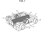
- Figure 1 is a perspective view of a general ventilating system.
- the ventilating system includes a case 2 mounted in a wall of a building which sections an outdoor side and an indoor side; blast fans 4 and 6 inserted in the case 2 and performing a ventilating operation on air being sucked and discharged, an air cleaner (not shown) installed at a portion in the case where outdoor air is sucked and cleaning outdoor air being sucked, and a heat exchanger 8 disposed inside the case 2 and performing heat exchanging between indoor air being discharged to the exterior of the building and outdoor air being sucked to the interior of the building
- the case 2 is mounted penetrating the wall sectioning the indoor side and the outdoor side. Thus, one side of the case is positioned at the interior of the building while the other side is positioned at the exterior of the building.
- An outdoor suction opening 10 through which outdoor air is sucked and an outdoor discharge opening 12 through which indoor air is discharged are formed at the outdoor side of the case 2.
- An indoor discharge opening 14 through which outdoor air is supplied and an indoor suction opening 16 through which indoor air is sucked are formed at the indoor side of the case 2.
- the discharging blast fans 4 is installed at one side of the outdoor discharge opening 12 and provides a blast pressure to discharge indoor air to outside of the building
- the sucking blast fan 6 is installed at one side of the indoor discharge opening 14 and provides a blast pressure to suck outdoor air to the interior of the building.
- FIG 2 is a perspective view of a heat exchanger for a ventilating system in accordance with a conventional art
- Figure 3 is a partial perspective view of the heat exchanger.
- a heat exchanger 8 in accordance with the conventional art includes: heat exchange plates 20 laminated with regular intervals so that a first air passage 26 through which indoor air passes and a second air passage 28 through which outdoor air passes are sequentially formed; first corrugation plates 22 attached to the first air passages 26 between the heat exchange plates 20 and obtaining a space for allowing indoor air to pass through; and second corrugation plates 24 attached to the second air passage 28 between the heat exchange plates 20 and obtaining a space to allow outdoor air to pass through.
- the heat exchange plates 20 are formed in a flat type, made of an aluminum material and carries out a heat exchanging operation between indoor air flowing through the first air passage 26 and outdoor air flowing through the second air passage 28.
- the first and second corrugation plates 22 and 24 are made of the same aluminum material as that of the heat exchange plates 20, and bent several times in a triangular form to obtain the space through which indoor air and outdoor air can pass.
- the heat exchanger 8 is constructed overall in a rectangular form as the first corrugation plates 22, the heat exchange plates 20 and the second corrugation plates 24 are sequentially laminated.
- the outdoor air being sucked absorbs heat contained in indoor air being discharged and is discharged to the interior of the building, so that a rapid change in an indoor temperature is prevented in a ventilating operation.
- the heat exchanging plate 20, the first corrugation plate 22 and the second corrugation plate 24 are made of the aluminum material, heat transfer is possible that heat of indoor air is transferred to outdoor air in terms of the properties of the aluminum material. But since moisture contained in indoor air fails to be transferred to outdoor air, although the change in the indoor temperature can be reduced after the ventilating operation, a humidity changes.
- Another object of the present invention is to provide a heat exchanger of a ventilating system that is capable of improving an indoor environment by radiating negative ions to outdoor air being supplied to the interior of a building.
- a heat exchanger of a ventilating system including: heat exchange plates laminated with regular intervals so that a first air passage through which indoor air being discharged to outside of a building passes and a second air passage through which outdoor air being introduced into the interior of the building passes are sequentially formed; first corrugation plates attached to the first air passage and obtaining a space to allow outdoor air to pass therethrough; and second corrugation plates attached to the second air passage and obtaining a space to allow outdoor air to pass therethrough, wherein the heat exchange plates are made of a Korean paper material with numerous fine holes that are able to generate a capillary phenomenon and one of: loess which radiates far infrared rays; charcoal which radiates negative ions; and active carbon that has an air cleaning function, wherein the Korean paper is fabricated with bast fiber of the paper mulberry as a key component.
- the heat exchange plate is fabricated by mixing a Korean paper made of bast fiber of the paper mulberry as a key component and loess radiating far infrared ray.
- the Korean paper contains 60 ⁇ 70% of holo cellulose, 10 ⁇ 20% of lignin and 5 ⁇ 10% of lime.
- the loess has particles with a size of 0.02 ⁇ 0.05mm.
- the loess has a composition of 60 ⁇ 65% silica (SiO 2 ), 10 ⁇ 13% alumina (Al 2 O 3 ), 5 ⁇ 6% iron content, 1 ⁇ 3% of magnesium, 2 ⁇ 3% of potassium carbonate, and 6 ⁇ 9% lime.
- the first corrugation plate and the second corrugation plate are made of an aluminum material.
- the first corrugation plate and the second corrugation plate are made of a paper material with numerous fine holes that are able to generate a capillary phenomenon and loess which radiates far infrared ray.
- the charcoal is fabricated by carbonizing a wood material at a temperature of 600 ⁇ 900°C and has carbon as a key component.
- the charcoal contains carbon of some 85%.
- the first corrugation plate and the second corrugation plate are fabricated with a Korean paper with numerous fine holes that are able to generate a capillary phenomenon and charcoal which radiates negative ions.
- the active carbon is fabricated by processing wood or brown coal with chemicals such as zinc chloride or phosphoric acid, an activation agent and drying it, or by activating charcoal with steam.
- the first corrugation plate and the second corrugation plate are fabricated with a paper material with numerous fine holes that are able to generate a capillary phenomenon and active carbon which has an air cleaning function.
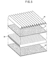
- Figure 4 is a perspective view of a heat exchanger of a ventilating system in accordance with one embodiment of the present invention.
- a ventilating system of the present invention includes a case 2 mounted penetratingly in a wall of a building which sections an outdoor side and an indoor side of the building. That is, one side of the case 2 is positioned at the exterior of the building while the other side of the case 2 is positioned at the interior of the building.
- the outdoor suction opening 10 through which outdoor air is sucked and an outdoor discharge opening 12 through which indoor air is discharged are respectively connected at the outdoor side of the case 2, while an indoor suction opening 14 through which indoor air is sucked and an indoor discharge opening 16 through which outdoor air is supplied to the interior of the building are connected at the indoor side of the case 2.
- a discharging blast fan 4 is installed to at one side of the outdoor discharge opening 12 to give a blast pressure to indoor air to discharge it to the exterior of the building, and a sucking blast fan 6 is installed at one side of the indoor discharge opening 14 to give outdoor air to suck it into the interior of the building.
- An air cleaner (not shown) is installed on a suction passage inside the case 2 to remove various impurities and dusts contained in outdoor air being sucked to the interior of the building, and a heat exchanger 8 is installed inside the case 2 to carry out a heat exchanging operation between indoor air being discharge to the exterior of the building and outdoor air being sucked to the interior of the building.
- the heat exchanger 8 includes heat exchange plates 54 laminated with predetermined intervals so that a first air passage 50 through which indoor air passes and a second air passage 52 through which outdoor air passes are sequentially formed; a first corrugation plate 56 attached on the first air passage 50 to obtain a space through which the indoor air passes; and a second corrugation plate 58 attached on the second air passage 52 to obtain a space through which the outdoor air passes.
- the heat exchanger 8 has a rectangular form in an overall shape, and the first corrugation plate 56 and the second corrugation plate 58 are arranged to be crossed, so that indoor air and outdoor air flow in the crossing manner, during which heat exchange is carried out through the heat exchange plates 54.
- the heat exchange plate 54 has a thin flat type and is made of a material which is able to pass moisture therethrough so that moisture contained in the indoor air flowing in the first air passage 50 can be transferred to outdoor air flowing in the second air passage 52, and which also has a cleaning function as well such as antibiosis and deodorization.
- the heat exchange plate is fabricated by mixing a Korean paper material with an excellent moisture absorption rate and loess which performs a purification function of removing various harmful materials contained in the outdoor air as well as antibiotic and mothproof functions by radiating far infrared ray to outdoor air being sucked to the interior of the building.
- the Korean paper is fabricated by a Korean particular method, of which main ingredient is the bast fiber of paper mulberry.
- the fabrication process of the Korean paper includes the steps of: bundling the paper mulberry, putting it in a container with water, boiling it to a degree that its skin is easily peeled off, peeling and drying them; soaking the dried skin of the paper mulberry in the water, sorting out only the bast fiber portion, putting the bast fiber portion in caustic soda and boiling it more than three hours, and wringing it with a compressor; putting the moisture-removed bast fiber in a liquid which has been prepared by mashing roots of the paper mulberry and pressing them out, and mixing them evenly, and filtering the resulting paper solution by using a sieve.
- the Korean paper completed by the fabrication process contains 60 ⁇ 70% of holo cellulose, 10 ⁇ 20% of lignin and 5 ⁇ 10% of lime. More specifically, it is preferred that the Korean paper comprises 67.5% of holo cellulose, 14.7% of lignin and 6.22% of lime.
- the Korean paper since its fibers are long in length, narrower in width, fibers are combined tightly, and in addition, since fibrils forming the fiber of cellulose are oriented in an axial direction, the fibers have a high strength. Thus, compared to the general paper, the Korean paper has such an advantage that it can be preserved for a long period. In addition, the numerous fine holes formed between fibers generate the capillary phenomenon, resulting in an excellent moisture absorption capacity.
- fabricating the heat exchange plate 54 with the Korean material ensures a latent heat function as moisture contained in indoor air is absorbed to the heat exchange plate 54, which is then transferred to outdoor air.
- the loess is a sort of soil that can be easily collected from soil and has particles with a size of 0.02-0.05 mm and chemical components of 60 ⁇ 65% silica (SiO 2 ), 10 ⁇ 13% alumina (Al 2 O 3 ), 5 ⁇ 6% of iron content, 1 ⁇ 3% of magnesium, 2 ⁇ 3% of potassium carbonate, and 6 ⁇ 9% lime, etc.
- the loess has a mineral composition comprising 60 ⁇ 70% quartz, 10 ⁇ 20% feldspar and mica, 5 ⁇ 25% carbonate, 2 ⁇ 5% of other minerals.
- the loess is mixed in water to have a certain viscosity, which is then applied to the heat exchanging plate, thereby completing formation of the heat exchange plate.
- the loess and the Korean paper can be mixed in other various methods.
- the first corrugation plate 56 and the second corrugation plate 58 can be fabricated with an aluminum material.
- the heat exchange plate 56 is made of the Korean paper material, so that a heat transfer performance of transferring heat of indoor air to outdoor air betters. And thanks to the capillary phenomenon occurring by the numerous fine holes formed in the heat exchange plate 54, moisture contained in the indoor air is absorbed to the heat transfer plate 56, which is then transferred to the outdoor air, according to which the outdoor air sucked to the interior of the building contains heat with a temperature as high as the indoor air being discharged to outside the building and moisture as much as that of the indoor air. Therefore, the temperature and moisture change in the indoor environment can be minimized in the ventilating operation.
- loess is contained in the heat exchange plate 54, far infrared ray is radiated to outdoor air being passed through the second air passage 52, performing a sterilization function and performing a purification function to remove harmful materials contained in the outdoor air. Therefore, clean air is supplied to the interior of the building.
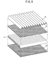
- Figure 6 is a perspective view of a heat exchanger in accordance with a second embodiment of the present invention.
- a heat exchanger in accordance with a second embodiment of the present invention has the same construction as that of the first embodiment of the present invention except that the heat exchange plate 70 is fabricated with a different material.
- the heat exchange plate 70 is made by mixing the Korean paper material with an excellent moisture absorption rate in transferring moisture contained in indoor air being discharged to outside the building to outdoor air being sucked to the interior of the building and charcoal which radiates negative ions to outdoor air being sucked to the interior of the building.
- the Korean paper in this connection has the same construction and is fabricated in the same manner as those in the first embodiment of the present invention, descriptions of which are thus omitted.
- Charcoal is made by primarily carbonizing wood at a temperature of 600 ⁇ 900°C, in which carbon accounts for as much as 85% as a major component.
- charcoal In the fabrication process of charcoal, numerous fine holes are formed in charcoal, so that various harmful materials can be adsorbed therethrough, and charcoal has an excellent air cleaning performance with its function of radiating negative ions.
- the heat exchanger in accordance with the second embodiment of the present invention has such an advantage that since the heat exchange plate 70 is fabricated by mixing the Korean paper and charcoal, the sensible heat exchange and the latent heat exchange can be simultaneously carried out, which is a property of the Korean paper, and indoor air can be purified by radiating negative ions, a property of charcoal, to outdoor air being supplied to the interior of the building.
- Figure 7 is an exploded perspective view of the heat exchanger of a ventilating system in accordance with a third embodiment of the present invention.
- a heat exchanger in accordance with a third embodiment of the present invention has the same construction as that of the first embodiment of the present invention except that the heat exchange plate 70 is fabricated with a different material.
- the heat exchange plate 80 is made by mixing the Korean paper material with an excellent moisture absorption rate in transferring moisture contained in indoor air being discharged to outside the building to outdoor air being sucked to the interior of the building and an active carbon which removes a harmful material contained in the air.
- the Korean paper in this connection has the same construction and is fabricated in the same manner as those in the first embodiment of the present invention, descriptions of which are thus omitted.
- the active carbon has a strong adsorption and mostly made of carbon and is fabricated by processing wood or brown coal with chemicals such as zinc chloride or phosphoric acid, an activation agent and drying it, or by activating charcoal with steam.
- the heat exchanger in accordance with the second embodiment of the present invention has such an advantage that since the heat exchange plate 80 is fabricated by mixing the Korean paper and active carbon, the sensible heat exchange and the latent heat exchange can be simultaneously carried out, which is the property of the Korean paper, and a harmful material contained in outdoor air being supplied to the interior of the building can be removed, which is the property of the active carbon.
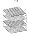
- Figure 8 is an exploded perspective view of the heat exchanger of a ventilating system in accordance with a fourth embodiment of the present invention.
- a heat exchanger in accordance with a fourth embodiment of the present invention has the same construction as that of the first embodiment of the present invention except that the heat exchange plate 80, the first corrugation plate 92 and the second corrugation plate 94 are fabricated with a different material.
- the heat exchange plate, the first corrugation plate and the second corrugation plate can be fabricated with a material obtained by mixing the Korean paper and loess, with a material obtained by mixing the Korean paper and charcoal, or with a material obtained by mixing the Korean paper and active carbon.
- the heat exchanger of a ventilating system in accordance with the present invention has the following advantages.
- the sensible heat exchange that heat contained in indoor air being discharged to outside a building is transferred to outdoor air being sucked to the interior of the building and a latent heat exchange that moisture contained in indoor air being discharged to outside the building is transferred to outdoor air being sucked to the interior of the building are simultaneously carried out.
- the far infrared ray radiated from loess performs a cleaning function of removing a harmful material contained in outdoor air, so that a change in temperature and humidity in the interior of the building can be minimized after a ventilating operation and air being supplied into the interior of the building can be cleaned.
- the sensible heat exchange that heat contained in indoor air being discharged to outside a building is transferred to outdoor air being sucked to the interior of the building and a latent heat exchange that moisture contained in indoor air being discharged to outside the building is transferred to outdoor air being sucked to the interior of the building are simultaneously carried out.
- the negative ions radiated from charcoal performs a cleaning function of removing a harmful material contained in outdoor air, so that a change in temperature and humidity in the interior of the building can be minimized after a ventilating operation and a clean air can be supplied into the interior of the building.
- the sensible heat transfer and the latent heat transfer are simultaneously carried out, so that air being supplied to the interior of the building can be purified.
Landscapes
- Engineering & Computer Science (AREA)
- Mechanical Engineering (AREA)
- General Engineering & Computer Science (AREA)
- Physics & Mathematics (AREA)
- Thermal Sciences (AREA)
- Chemical & Material Sciences (AREA)
- Combustion & Propulsion (AREA)
- Heat-Exchange Devices With Radiators And Conduit Assemblies (AREA)
- Building Environments (AREA)
- Drying Of Gases (AREA)
- Central Air Conditioning (AREA)
Claims (11)
- Wärmetauscher (8) eines Lüftungssystems, umfassend:mit regelmäßigen Abständen derart geschichtete Wärmetauschplatten (54), dass aufeinander folgend ein erster Luftdurchlass (50), durch den nach außerhalb eines Gebäudes abgeführte Innenluft verläuft, und ein zweiter Luftdurchlass (52), durch den in das Gebäudeinnere eingeführte Außenluft verläuft, ausgebildet sind;erste, dem ersten Luftdurchlass (50) zugeordnete Wellplatten (56), die Raum schaffen, um das Hindurchlaufen von Außenluft zu ermöglichen; undzweite, dem zweiten Luftdurchlass (52) zugeordnete Wellplatten (58), die Raum schaffen, um das Hindurchlaufen von Außenluft zu ermöglichen,wobei die Wärmetauschplatten (54) aus einem Koreanischen Papiermaterial mit zahlreichen feinen, zum Erzeugen eines Kapillarphänomens geeigneten Löchern undentweder Löss, der Ferninfrarotstrahlung abstrahlt; oder künstliche Kohle, die negative Ionen abstrahlt; oder Aktivkohle, die eine Luftreinigungsfunktion aufweist, hergestellt sind,wobei das Koreanische Papier aus Bastfaser der Papiermaulbeere als Hauptbestandteil hergestellt ist.
- Wärmetauscher nach Anspruch 1, bei dem das Koreanische Papier 60 bis 70% an Holozellulose, 10 bis 20% an Lignin und 5 bis 10% an Kalk enthält.
- Wärmetauscher nach Anspruch 1, bei dem der Löss Partikel mit einer Größe von 0,02 bis 0,05 mm aufweist.
- Wärmetauscher nach Anspruch 3, bei dem der Löss ein Zusammensetzungsverhältnis von 60 bis 65% Siliziumdioxid (BiO2), 10 bis 13% Aluminiumoxid (Al2O3), 5 bis 6% Eisengehalt, 1 bis 3% Magnesium, 2 bis 3% Kaliumkarbonat und 6 bis 9% Kalk aufweist.
- Wärmetauscher nach Anspruch 1, bei dem die erste Wellplatte (56) und die zweite Wellplatte (58) aus einem Aluminiummaterial hergestellt sind.
- Wärmetauscher nach Anspruch 1, bei dem die ersten (56) und zweiten (58) Wellplatten aus einem Papiermaterial mit zahlreichen feinen, zum Erzeugen eines Kapillarphänomens geeigneten Löchern und Löss, der Ferninfrarotstrahlung abstrahlt, hergestellt sind.
- Wärmetauscher nach Anspruch 1, bei dem die künstliche Kohle durch Verkoken von Holzmaterial bei einer Temperatur von 600 bis 900°C hergestellt wird und Kohlenstoff als Hauptbestandteil aufweist.
- Wärmetauscher nach Anspruch 7, bei dem die künstliche Kohle etwa 85% Kohlenstoff enthält.
- Wärmetauscher nach Anspruch 1, bei dem die ersten Wellplatten (56) und die zweiten Wellplatten (58) aus Koreanischem Papier mit zahlreichen feinen, zum Erzeugen eines Kapillarphänomens geeigneten Löchern und künstlicher Kohle, die negative Ionen abstrahlt, hergestellt sind.
- Wärmetauscher nach Anspruch 1, bei dem die Aktivkohle durch Bearbeiten von Holz oder Braunkohle mit Chemikalien, wie Zinkchlorid oder Phosphorsäure, einem Aktivierungsmittel und Trocknen, oder durch Aktivieren von künstlicher Kohle durch Dampf hergestellt wird.
- Wärmetauscher nach Anspruch 1, bei dem die ersten Wellplatten (56) und die zweiten Wellplatten (58) aus einem Papiermaterial mit zahlreichen feinen, zum Erzeugen eines Kapillarphänomens geeigneten Löchern und eine luftreinigende Funktion aufweisender Aktivkohle hergestellt sind.
Applications Claiming Priority (1)
| Application Number | Priority Date | Filing Date | Title |
|---|---|---|---|
| PCT/KR2003/000245 WO2004070312A1 (en) | 2003-02-04 | 2003-02-04 | Heat exchanger of ventilating system |
Publications (2)
| Publication Number | Publication Date |
|---|---|
| EP1590621A1 EP1590621A1 (de) | 2005-11-02 |
| EP1590621B1 true EP1590621B1 (de) | 2008-07-09 |
Family
ID=32844740
Family Applications (1)
| Application Number | Title | Priority Date | Filing Date |
|---|---|---|---|
| EP03703497A Expired - Lifetime EP1590621B1 (de) | 2003-02-04 | 2003-02-04 | Warmetauscher eines belüftungssystems |
Country Status (8)
| Country | Link |
|---|---|
| US (1) | US7188666B2 (de) |
| EP (1) | EP1590621B1 (de) |
| CN (1) | CN100526733C (de) |
| AT (1) | ATE400789T1 (de) |
| AU (1) | AU2003206235B2 (de) |
| DE (1) | DE60322118D1 (de) |
| ES (1) | ES2307897T3 (de) |
| WO (1) | WO2004070312A1 (de) |
Families Citing this family (25)
| Publication number | Priority date | Publication date | Assignee | Title |
|---|---|---|---|---|
| NO321435B1 (no) * | 2003-08-12 | 2006-05-08 | Volstad Energy As | Anordning for a regulere temperatur og damptrykk i en konstruksjon |
| KR100630393B1 (ko) | 2004-09-01 | 2006-09-29 | 주식회사 벤토피아 | 한지를 이용한 열교환부재를 구비한 전열교환기 |
| TWI326691B (en) | 2005-07-22 | 2010-07-01 | Kraton Polymers Res Bv | Sulfonated block copolymers, method for making same, and various uses for such block copolymers |
| JP4994450B2 (ja) | 2007-06-18 | 2012-08-08 | 三菱電機株式会社 | 熱交換素子およびその製造方法ならびに熱交換器および熱交換換気装置 |
| US7877929B2 (en) | 2007-08-04 | 2011-02-01 | Rezzorb, Llc | Method and apparatus for reducing fertilizer use in agricultural operations |
| LT5511B (lt) | 2007-08-21 | 2008-08-25 | Edvardas RAČKAUSKAS | Šilumokaitis |
| KR20100120313A (ko) * | 2008-04-16 | 2010-11-15 | 미쓰비시덴키 가부시키가이샤 | 열교환 환기장치 |
| US8012539B2 (en) | 2008-05-09 | 2011-09-06 | Kraton Polymers U.S. Llc | Method for making sulfonated block copolymers, method for making membranes from such block copolymers and membrane structures |
| KR100938802B1 (ko) * | 2009-06-11 | 2010-01-27 | 국방과학연구소 | 마이크로채널 열교환기 |
| DE102009027879A1 (de) * | 2009-07-21 | 2011-01-27 | BSH Bosch und Siemens Hausgeräte GmbH | Haltevorrichtung für Flaschen insbesondere zur Anordnung in einem Kältegerät |
| US8445631B2 (en) | 2009-10-13 | 2013-05-21 | Kraton Polymers U.S. Llc | Metal-neutralized sulfonated block copolymers, process for making them and their use |
| US8263713B2 (en) * | 2009-10-13 | 2012-09-11 | Kraton Polymers U.S. Llc | Amine neutralized sulfonated block copolymers and method for making same |
| BE1019687A3 (fr) | 2010-06-11 | 2012-10-02 | Greencom Dev Scrl | Corps d'echange thermique et echangeur comprenant un tel corps d'echange. |
| US9394414B2 (en) | 2010-09-29 | 2016-07-19 | Kraton Polymers U.S. Llc | Elastic, moisture-vapor permeable films, their preparation and their use |
| US9429366B2 (en) * | 2010-09-29 | 2016-08-30 | Kraton Polymers U.S. Llc | Energy recovery ventilation sulfonated block copolymer laminate membrane |
| BR112013007705A2 (pt) | 2010-10-18 | 2016-08-09 | Kraton Polymers Us Llc | solução tendo uma composição de copolímero em bloco sulfonado, película ou membrana, dispersão aquosa, compósito, composição de copolímeto em bloco sulfonado, processo, método para formar uma composição de copolímero em bloco sulfonado, e, célula eletrodialítica |
| JP5845388B2 (ja) * | 2011-03-10 | 2016-01-20 | パナソニックIpマネジメント株式会社 | 熱交換形換気装置 |
| US9861941B2 (en) | 2011-07-12 | 2018-01-09 | Kraton Polymers U.S. Llc | Modified sulfonated block copolymers and the preparation thereof |
| US10041743B2 (en) * | 2013-01-07 | 2018-08-07 | Carrier Corporation | Energy recovery ventilator |
| TWI496918B (zh) * | 2013-02-05 | 2015-08-21 | Adpv Technology Ltd Intetrust | Gas release device for coating process |
| US9873547B2 (en) | 2013-03-15 | 2018-01-23 | Tippmann Companies Llc | Heat transfer system for warehoused goods |
| CN105651098B (zh) * | 2015-12-31 | 2018-12-18 | 上海交通大学 | 一种全热换热器功能层材料的改进方法 |
| CN110686394A (zh) * | 2019-09-18 | 2020-01-14 | 珠海格力电器股份有限公司 | 一种全热交换芯体和空调机 |
| US11391487B2 (en) | 2020-09-17 | 2022-07-19 | Bradford D Wallace | Air to air cross flow heat and moisture exchanger |
| CN113218060B (zh) * | 2021-03-26 | 2022-04-15 | 深圳通利机电工程有限公司 | 节能式中央空调系统的多级热回收新风处理装置 |
Family Cites Families (10)
| Publication number | Priority date | Publication date | Assignee | Title |
|---|---|---|---|---|
| US4051898A (en) * | 1969-03-20 | 1977-10-04 | Mitsubishi Denki Kabushiki Kaisha | Static heat-and-moisture exchanger |
| US3666007A (en) * | 1970-03-17 | 1972-05-30 | Mitsubishi Electric Corp | Apparatus for effecting continuous and simultaneous transfer of heat and moisture between two air streams |
| JPS5579996A (en) * | 1978-12-14 | 1980-06-16 | Teijin Ltd | Wet heat exchanger |
| JPS563900A (en) * | 1979-06-26 | 1981-01-16 | Daikin Ind Ltd | Total heat exchange-type heat exchanger |
| JPS5782694A (en) * | 1980-11-11 | 1982-05-24 | Nippon Soken Inc | Air ventilation heat exchanger |
| JPS6065199A (ja) * | 1983-09-21 | 1985-04-13 | 株式会社興人 | 繊維状チタン酸アルカリ金属塩の抄造方法 |
| CA2059195C (en) * | 1992-01-10 | 1995-01-31 | Rene Morissette | Defrostable ventilation system |
| US6182747B1 (en) * | 1995-09-13 | 2001-02-06 | Nautica Dehumidifiers, Inc. | Plate-type crossflow air-to-air heat-exchanger comprising side-by-side-multiple small-plates |
| JP3977514B2 (ja) * | 1998-05-26 | 2007-09-19 | 高砂熱学工業株式会社 | 空気浄化フィルタ及びその製造方法及び高度清浄装置 |
| CA2283089C (en) * | 1999-05-10 | 2004-05-25 | Mitsubishi Denki Kabushiki Kaisha | Heat exchanger and method for preparing it |
-
2003
- 2003-02-04 ES ES03703497T patent/ES2307897T3/es not_active Expired - Lifetime
- 2003-02-04 WO PCT/KR2003/000245 patent/WO2004070312A1/en not_active Ceased
- 2003-02-04 EP EP03703497A patent/EP1590621B1/de not_active Expired - Lifetime
- 2003-02-04 CN CNB038258560A patent/CN100526733C/zh not_active Expired - Fee Related
- 2003-02-04 DE DE60322118T patent/DE60322118D1/de not_active Expired - Lifetime
- 2003-02-04 US US10/538,070 patent/US7188666B2/en not_active Expired - Fee Related
- 2003-02-04 AU AU2003206235A patent/AU2003206235B2/en not_active Ceased
- 2003-02-04 AT AT03703497T patent/ATE400789T1/de not_active IP Right Cessation
Also Published As
| Publication number | Publication date |
|---|---|
| WO2004070312A1 (en) | 2004-08-19 |
| ATE400789T1 (de) | 2008-07-15 |
| ES2307897T3 (es) | 2008-12-01 |
| CN100526733C (zh) | 2009-08-12 |
| US20060113070A1 (en) | 2006-06-01 |
| AU2003206235A1 (en) | 2004-08-30 |
| US7188666B2 (en) | 2007-03-13 |
| EP1590621A1 (de) | 2005-11-02 |
| CN1735771A (zh) | 2006-02-15 |
| AU2003206235B2 (en) | 2007-09-06 |
| DE60322118D1 (de) | 2008-08-21 |
Similar Documents
| Publication | Publication Date | Title |
|---|---|---|
| US7188666B2 (en) | Heat exchanger of ventilating system | |
| US7168482B2 (en) | Heat exchanger of ventilating system | |
| EP1975523A1 (de) | Entfeuchter und Entfeuchtungsverfahren | |
| CN111928355A (zh) | 用于湿度调节的装置 | |
| CN107166531A (zh) | 一种带除湿功能的新风交换机 | |
| CN208253739U (zh) | 一种具有清洁空气作用的空调净化装置 | |
| AU2003206227B2 (en) | Heat exchanger of ventilating system | |
| KR101017574B1 (ko) | 점착 및 접착식 공기여과필터 | |
| CN113566321A (zh) | 除湿装置 | |
| EP1702182B1 (de) | Im wärmetauscher eines ventilators verwendetes funktionales papier | |
| CN116950185A (zh) | 一种制水装置 | |
| CN210448388U (zh) | 一种过滤装置及空气净化器 | |
| CN220083179U (zh) | 风管式空调机 | |
| CN220319425U (zh) | 一种新型净化门 | |
| KR101922628B1 (ko) | 파티션 | |
| CN222715653U (zh) | 加热模块、烘干模组与衣物处理设备 | |
| CN223826427U (zh) | 一种节能型的洁净式空调机组 | |
| CN220958831U (zh) | 一种新型高效热回收新风机 | |
| CN223630657U (zh) | 一种玻璃切割设备的吸尘装置 | |
| CN104791928A (zh) | 一种非绝热型除湿设备 | |
| CN221648625U (zh) | 泳池除湿热泵 | |
| CN102309908B (zh) | 除湿机 | |
| CN218922100U (zh) | 一种节能型石墨烯家具 | |
| CN203571937U (zh) | 一种新风换气机 | |
| CN214619881U (zh) | 一种多模块冷热水泳池除湿热泵机组 |
Legal Events
| Date | Code | Title | Description |
|---|---|---|---|
| PUAI | Public reference made under article 153(3) epc to a published international application that has entered the european phase |
Free format text: ORIGINAL CODE: 0009012 |
|
| 17P | Request for examination filed |
Effective date: 20050609 |
|
| AK | Designated contracting states |
Kind code of ref document: A1 Designated state(s): AT BE BG CH CY CZ DE DK EE ES FI FR GB GR IE IT LI LU MC NL PT SE SI SK TR |
|
| AX | Request for extension of the european patent |
Extension state: AL LT LV MK RO |
|
| DAX | Request for extension of the european patent (deleted) | ||
| 17Q | First examination report despatched |
Effective date: 20070316 |
|
| GRAP | Despatch of communication of intention to grant a patent |
Free format text: ORIGINAL CODE: EPIDOSNIGR1 |
|
| GRAS | Grant fee paid |
Free format text: ORIGINAL CODE: EPIDOSNIGR3 |
|
| GRAA | (expected) grant |
Free format text: ORIGINAL CODE: 0009210 |
|
| AK | Designated contracting states |
Kind code of ref document: B1 Designated state(s): AT BE BG CH CY CZ DE DK EE ES FI FR GB GR IE IT LI LU MC NL PT SE SI SK TR |
|
| REG | Reference to a national code |
Ref country code: GB Ref legal event code: FG4D |
|
| REG | Reference to a national code |
Ref country code: CH Ref legal event code: EP |
|
| REF | Corresponds to: |
Ref document number: 60322118 Country of ref document: DE Date of ref document: 20080821 Kind code of ref document: P |
|
| REG | Reference to a national code |
Ref country code: IE Ref legal event code: FG4D |
|
| REG | Reference to a national code |
Ref country code: ES Ref legal event code: FG2A Ref document number: 2307897 Country of ref document: ES Kind code of ref document: T3 |
|
| NLV1 | Nl: lapsed or annulled due to failure to fulfill the requirements of art. 29p and 29m of the patents act | ||
| PG25 | Lapsed in a contracting state [announced via postgrant information from national office to epo] |
Ref country code: PT Free format text: LAPSE BECAUSE OF FAILURE TO SUBMIT A TRANSLATION OF THE DESCRIPTION OR TO PAY THE FEE WITHIN THE PRESCRIBED TIME-LIMIT Effective date: 20081209 Ref country code: NL Free format text: LAPSE BECAUSE OF FAILURE TO SUBMIT A TRANSLATION OF THE DESCRIPTION OR TO PAY THE FEE WITHIN THE PRESCRIBED TIME-LIMIT Effective date: 20080709 |
|
| PG25 | Lapsed in a contracting state [announced via postgrant information from national office to epo] |
Ref country code: SI Free format text: LAPSE BECAUSE OF FAILURE TO SUBMIT A TRANSLATION OF THE DESCRIPTION OR TO PAY THE FEE WITHIN THE PRESCRIBED TIME-LIMIT Effective date: 20080709 Ref country code: FI Free format text: LAPSE BECAUSE OF FAILURE TO SUBMIT A TRANSLATION OF THE DESCRIPTION OR TO PAY THE FEE WITHIN THE PRESCRIBED TIME-LIMIT Effective date: 20080709 Ref country code: BG Free format text: LAPSE BECAUSE OF FAILURE TO SUBMIT A TRANSLATION OF THE DESCRIPTION OR TO PAY THE FEE WITHIN THE PRESCRIBED TIME-LIMIT Effective date: 20081009 Ref country code: AT Free format text: LAPSE BECAUSE OF FAILURE TO SUBMIT A TRANSLATION OF THE DESCRIPTION OR TO PAY THE FEE WITHIN THE PRESCRIBED TIME-LIMIT Effective date: 20080709 |
|
| PG25 | Lapsed in a contracting state [announced via postgrant information from national office to epo] |
Ref country code: BE Free format text: LAPSE BECAUSE OF FAILURE TO SUBMIT A TRANSLATION OF THE DESCRIPTION OR TO PAY THE FEE WITHIN THE PRESCRIBED TIME-LIMIT Effective date: 20080709 |
|
| PG25 | Lapsed in a contracting state [announced via postgrant information from national office to epo] |
Ref country code: DK Free format text: LAPSE BECAUSE OF FAILURE TO SUBMIT A TRANSLATION OF THE DESCRIPTION OR TO PAY THE FEE WITHIN THE PRESCRIBED TIME-LIMIT Effective date: 20080709 Ref country code: EE Free format text: LAPSE BECAUSE OF FAILURE TO SUBMIT A TRANSLATION OF THE DESCRIPTION OR TO PAY THE FEE WITHIN THE PRESCRIBED TIME-LIMIT Effective date: 20080709 |
|
| PLBE | No opposition filed within time limit |
Free format text: ORIGINAL CODE: 0009261 |
|
| STAA | Information on the status of an ep patent application or granted ep patent |
Free format text: STATUS: NO OPPOSITION FILED WITHIN TIME LIMIT |
|
| PG25 | Lapsed in a contracting state [announced via postgrant information from national office to epo] |
Ref country code: SK Free format text: LAPSE BECAUSE OF FAILURE TO SUBMIT A TRANSLATION OF THE DESCRIPTION OR TO PAY THE FEE WITHIN THE PRESCRIBED TIME-LIMIT Effective date: 20080709 Ref country code: CZ Free format text: LAPSE BECAUSE OF FAILURE TO SUBMIT A TRANSLATION OF THE DESCRIPTION OR TO PAY THE FEE WITHIN THE PRESCRIBED TIME-LIMIT Effective date: 20080709 |
|
| 26N | No opposition filed |
Effective date: 20090414 |
|
| PG25 | Lapsed in a contracting state [announced via postgrant information from national office to epo] |
Ref country code: MC Free format text: LAPSE BECAUSE OF NON-PAYMENT OF DUE FEES Effective date: 20090228 |
|
| REG | Reference to a national code |
Ref country code: CH Ref legal event code: PL |
|
| GBPC | Gb: european patent ceased through non-payment of renewal fee |
Effective date: 20090204 |
|
| PG25 | Lapsed in a contracting state [announced via postgrant information from national office to epo] |
Ref country code: LI Free format text: LAPSE BECAUSE OF NON-PAYMENT OF DUE FEES Effective date: 20090228 Ref country code: CH Free format text: LAPSE BECAUSE OF NON-PAYMENT OF DUE FEES Effective date: 20090228 |
|
| REG | Reference to a national code |
Ref country code: FR Ref legal event code: ST Effective date: 20091030 |
|
| PG25 | Lapsed in a contracting state [announced via postgrant information from national office to epo] |
Ref country code: SE Free format text: LAPSE BECAUSE OF FAILURE TO SUBMIT A TRANSLATION OF THE DESCRIPTION OR TO PAY THE FEE WITHIN THE PRESCRIBED TIME-LIMIT Effective date: 20081009 Ref country code: IE Free format text: LAPSE BECAUSE OF NON-PAYMENT OF DUE FEES Effective date: 20090204 |
|
| PG25 | Lapsed in a contracting state [announced via postgrant information from national office to epo] |
Ref country code: FR Free format text: LAPSE BECAUSE OF NON-PAYMENT OF DUE FEES Effective date: 20090302 Ref country code: GB Free format text: LAPSE BECAUSE OF NON-PAYMENT OF DUE FEES Effective date: 20090204 |
|
| PGFP | Annual fee paid to national office [announced via postgrant information from national office to epo] |
Ref country code: ES Payment date: 20100216 Year of fee payment: 8 |
|
| PG25 | Lapsed in a contracting state [announced via postgrant information from national office to epo] |
Ref country code: GR Free format text: LAPSE BECAUSE OF FAILURE TO SUBMIT A TRANSLATION OF THE DESCRIPTION OR TO PAY THE FEE WITHIN THE PRESCRIBED TIME-LIMIT Effective date: 20081010 |
|
| PG25 | Lapsed in a contracting state [announced via postgrant information from national office to epo] |
Ref country code: LU Free format text: LAPSE BECAUSE OF NON-PAYMENT OF DUE FEES Effective date: 20090204 |
|
| PG25 | Lapsed in a contracting state [announced via postgrant information from national office to epo] |
Ref country code: TR Free format text: LAPSE BECAUSE OF FAILURE TO SUBMIT A TRANSLATION OF THE DESCRIPTION OR TO PAY THE FEE WITHIN THE PRESCRIBED TIME-LIMIT Effective date: 20080709 |
|
| PG25 | Lapsed in a contracting state [announced via postgrant information from national office to epo] |
Ref country code: CY Free format text: LAPSE BECAUSE OF FAILURE TO SUBMIT A TRANSLATION OF THE DESCRIPTION OR TO PAY THE FEE WITHIN THE PRESCRIBED TIME-LIMIT Effective date: 20080709 |
|
| REG | Reference to a national code |
Ref country code: ES Ref legal event code: FD2A Effective date: 20120411 |
|
| PG25 | Lapsed in a contracting state [announced via postgrant information from national office to epo] |
Ref country code: ES Free format text: LAPSE BECAUSE OF NON-PAYMENT OF DUE FEES Effective date: 20110205 |
|
| PGFP | Annual fee paid to national office [announced via postgrant information from national office to epo] |
Ref country code: DE Payment date: 20150113 Year of fee payment: 13 Ref country code: IT Payment date: 20150225 Year of fee payment: 13 |
|
| REG | Reference to a national code |
Ref country code: DE Ref legal event code: R119 Ref document number: 60322118 Country of ref document: DE |
|
| PG25 | Lapsed in a contracting state [announced via postgrant information from national office to epo] |
Ref country code: IT Free format text: LAPSE BECAUSE OF NON-PAYMENT OF DUE FEES Effective date: 20160204 |
|
| PG25 | Lapsed in a contracting state [announced via postgrant information from national office to epo] |
Ref country code: DE Free format text: LAPSE BECAUSE OF NON-PAYMENT OF DUE FEES Effective date: 20160901 |