EP1591004B1 - Presse à balles rondes - Google Patents
Presse à balles rondes Download PDFInfo
- Publication number
- EP1591004B1 EP1591004B1 EP04252515A EP04252515A EP1591004B1 EP 1591004 B1 EP1591004 B1 EP 1591004B1 EP 04252515 A EP04252515 A EP 04252515A EP 04252515 A EP04252515 A EP 04252515A EP 1591004 B1 EP1591004 B1 EP 1591004B1
- Authority
- EP
- European Patent Office
- Prior art keywords
- bale
- chamber
- baler according
- guide
- apron
- Prior art date
- Legal status (The legal status is an assumption and is not a legal conclusion. Google has not performed a legal analysis and makes no representation as to the accuracy of the status listed.)
- Expired - Lifetime
Links
Images


Classifications
-
- A—HUMAN NECESSITIES
- A01—AGRICULTURE; FORESTRY; ANIMAL HUSBANDRY; HUNTING; TRAPPING; FISHING
- A01F—PROCESSING OF HARVESTED PRODUCE; HAY OR STRAW PRESSES; DEVICES FOR STORING AGRICULTURAL OR HORTICULTURAL PRODUCE
- A01F15/00—Baling presses for straw, hay or the like
- A01F15/08—Details
-
- A—HUMAN NECESSITIES
- A01—AGRICULTURE; FORESTRY; ANIMAL HUSBANDRY; HUNTING; TRAPPING; FISHING
- A01F—PROCESSING OF HARVESTED PRODUCE; HAY OR STRAW PRESSES; DEVICES FOR STORING AGRICULTURAL OR HORTICULTURAL PRODUCE
- A01F15/00—Baling presses for straw, hay or the like
- A01F15/08—Details
- A01F15/18—Endless belts, rolls or the like
-
- A—HUMAN NECESSITIES
- A01—AGRICULTURE; FORESTRY; ANIMAL HUSBANDRY; HUNTING; TRAPPING; FISHING
- A01F—PROCESSING OF HARVESTED PRODUCE; HAY OR STRAW PRESSES; DEVICES FOR STORING AGRICULTURAL OR HORTICULTURAL PRODUCE
- A01F15/00—Baling presses for straw, hay or the like
- A01F15/07—Rotobalers, i.e. machines for forming cylindrical bales by winding and pressing
- A01F2015/077—Pressing chamber formed by belts and rollers
Definitions
- This invention relates to a baler for forming a cylindrical bale of agricultural crop material.
- balers for forming cylindrical bales of agricultural crop material are well known, and such bales are usually referred to as "round" bales.
- the baler has a bale-forming chamber, means for feeding crop material into the chamber, and an endless belt arrangement (apron) and possibly a series of circumferentially spaced rollers which define a part-cylindrical surface of the chamber and within which a cylindrical bale can be formed.
- balers can be of the "fixed chamber” or "variable chamber type", and the present invention is applicable to both types.
- the invention is concerned with a baler of the type having an apron formed by at least one endless belt which is arranged to define a part-cylindrical surface of the chamber and within which a cylindrical bale can be formed.
- the bale-forming chamber is therefore formed partly by the apron, which is formed by at least one endless belt, and also by an opposed pair of side surfaces which co-operate with the apron to define the bale-forming chamber, with each side surface facing a respective circular end face of the bale as it is formed.
- a guide path is provided for the endless belt which include at least two guide rollers arranged to be substantially shielded from the chamber by the belt, i.e. the two guide rollers are located internally of the apron, in the sense of being located internally of the endless guide path along which the endless belt is guided.
- balers It is an inevitable technical problem with existing balers that, from time to time, some of the material which is being fed into the chamber becomes entangled with, or wraps itself around or otherwise attaches to some of the guide rollers which define the endless path for the belt. Also, some of this material also collects loosely in the internal space, enclosed by the path of travel of the endless belt (apron).
- a disadvantage of the known arrangements is that the material which is scraped-off and leaves the belts falls onto the ground, and is therefore spoiled or the material that is leaving falls onto the pick-up device, or is lead otherwise onto it, and therefore the material has to travel a long way, with risk of material building up and risk of blockages. Also, other devices present might block the way between the belt outlet and the pick-up device. A disadvantage of leading the material through the side wall is spoilage, or the long and complicated route to the pick-up device, causing the risk of blockage along this route. Also, in case of material which accumulates in the internal space of the apron and leaves this space suffers from the same disadvantages.
- baler of the invention are set out in dependent Claims 2 to 14.
- the bale-forming chamber is defined by one or more apron consisting of an endless belt, or set of side-by-side arranged endless belts, running over at least two rollers; the chamber is also defined by two opposed side walls, and preferably also alongside the circumference of the compressed bale are provided one or more compression rollers.
- Material to be fed to the chamber may be picked-up by a pick-up device and, if available, such material may also be chopped-up prior to being fed into the chamber.
- the material Upon entry into the chamber, the material is compressed against the apron, and also against the preferred additional compression rollers.
- the cylindrical shape of the bale is maintained by applying twine or netting around the cylindrical surface of the bale, to maintain the compression of the bale.
- the bale is then ejected by opening a tailgate.
- scraped-off material can be led into a channel or duct in a side plate, thereby communicating the material (scraped-off from internally of the belts) with the bale chamber.
- the rotation of the bale is such as to pull the scraped-off material (by frictional contact) out of the channel and into the bale chamber. Therefore, there is no risk of spoilage of the material, in that there is direct transfer of the scraped-off material into the bale chamber, and also no risk of blockage.
- the outlet end of the channel where it opens into the bale chamber is wedge shaped (and preferably in the turning sense of the turning top end of the bale) to support the pulling of the material into the bale chamber via frictional contact with the turning upper end of the bale.
- the wedge is formed by the circumferential surface of a cylindrical or conical roller, having a surface which runs at the same turning speed and/or the same turning sense as the top end of the co-operating top end of the bale.
- the roller can be power driven. This is to support the transfer of material into the bale chamber.
- the material scraped-off the roller is preferably transported in a direction transversely of the direction of travel of the baler, i.e. generally parallel to the axis of the roller. This may be by employing a conveyor as disclosed in EPA 510499, EPA 201898, or by other means.
- a baler according to the invention is designated generally by reference 10, and as shown in Figure 3 is a wheeled trailed machine intended to be towed behind a tractor or other propelling vehicle via towbar 11.
- the baler will normally pick-up crop material which has already been cut or mown, and which is lying on the ground.
- a pick-up device 12 picks up the crop material, and feeds it to a rotary feeding device 13, which is preferably also a chopping device, and the chopped material is then fed to an inlet 14 to a bale-forming chamber 15 as shown by the arrow 16.
- An apron 17 is formed by at least one endless belt, and which is arranged to define a part-cylindrical surface of the chamber 15 and within which a progressively increasing size of cylindrical bale can be formed, in the case of a variable chamber type baler.
- the invention is, however, also applicable to a fixed chamber type of baler, although no detailed example is disclosed herein.
- a number of separate endless belts 18 are arranged side-by-side, and follow a usual path of travel, as shown in Figure 3, passing over a series of guide rollers.
- guide roller 19 which applies motion reversal substantially to the belts 18, and such a roller is particularly susceptible to crop material migrating to it and becoming wrapped around the roller, or otherwise attached to it.
- guide roller 19 is located internally of the endless path defined by the belts 18, i.e. internally of the apron. In other words, roller 19 is shielded from direct contact with the material in the chamber 15 by the belts themselves.
- the preferred embodiment of the invention provides a unique arrangement of scraper device, and co-operating guide passage, to remove any crop material which becomes wound on or attached to one of the rollers e.g. roller 19, of the endless belts, and provides a guide passage which receives the material scraped-off by the scraper device and guides such material into the bale-forming chamber 15.
- the bale-forming chamber 15 is defined partly by the part cylindrical surface defined by the movement of the endless belts 18, but also by a pair of opposed side surfaces each facing a respective circular end face of the bale as it is formed.
- One of the side surfaces is formed by a side face 20 of a housing of the baler designated generally by reference 21.
- a scraper device is therefore arranged to scrape-off any crop material which becomes attached to roller 19, and in the illustrated embodiment takes the form of a flighted auger type conveyor 22.
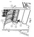
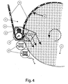
- the cooperation between the cylindrical surface of roller 19 and the auger 22 can be seen also in Figures 1, 2 and 4, as well as schematically in Figure 3.
- a guide passage is arranged to receive material scraped-off by the auger 22, and to guide such material into the bale-forming chamber.
- the guide passage is formed by a channel or duct 23 located at or in the end surface 20, and which guides scraped-off material from one axial end of the auger 22 (the auger 22 moves the material transversely and generally parallel to the axis of the roller 19), and the material then is guided rearwardly from its inlet end 24 adjacent to the auger 22, to an outlet end 25 via which the material is led into the chamber 15, in an upper portion thereof.
- the rotating mass of material forming the bale makes frictional contact with the scraped-off material as it moves along the channel 23, and this promotes pulling action on the scraped-off material.
- the outlet end 25 of the channel 23 is therefore wedge shaped, and preferably in the turning sense of the turning upper end of the bale, to support the pulling of the material into the bale chamber.
- the "wedge" may be formed by the circumferential surface of a cylindrical or conical roller, such surface running at the same turning speed and/or in the same turning sense as the upper end of the cooperating upper end of the bale.
- the roller can be power driven, in order to support the transfer of material into the bale chamber.
- the preferred embodiment of the invention therefore provides a unique arrangement of scraper device to remove material attaching itself to one of the guide rollers of the endless guide path for the belt(s), plus a unique cooperating guide passage to lead the scraped-off material directly into the bale-forming chamber, thereby minimising risk of spoilage.
- the preferred embodiment shows the scraper device associated with guide roller 19, but it should be understood that the invention may be applied to other guide rollers, and that more than one guide roller may have its own associated scraper device.
- At least one compression roller 26 is arranged adjacent to the outer periphery of the bale-forming chamber 15, in a region circumferentially spaced from the apron 17 and engageable directly with the outer periphery of the bale as it is being formed in the chamber.
- the scraper device (auger 22) may be omitted, but the guide passage (channel 23) remains and in operation can serve to feed any material which accumulates in the internal space 27 (defined internally of the path of travel of the endless belts 18) to the bale-forming chamber 15.
- This material is pulled and/or drawn-in by suction through the channel inlet 24 and moves along the channel 23 before entering the bale-forming chamber 15 via the channel outlet 25.
- This movement of the material may be generated and/or assisted by the pulling action of the rotating mass of the bale as it is being formed.
Landscapes
- Life Sciences & Earth Sciences (AREA)
- Environmental Sciences (AREA)
- Storage Of Harvested Produce (AREA)
- Toys (AREA)
- Finger-Pressure Massage (AREA)
- Food-Manufacturing Devices (AREA)
Claims (14)
- Presse à balles (10) pour former une balle cylindrique d'une matière de récolte agricole et comportant :une chambre de formation de balle (15) :une entrée d'alimentation (14) vers la chambre (15) ;des moyens (12, 13) pour alimenter de la matière de récolte vers l'entrée (14) et dans la chambre (15) ;un tablier (17) formé par au moins une courroie sans fin (18) qui est agencée pour définir une surface de partie cylindrique de la chambre (15) et dans lequel une balle cylindrique peut être formée ;un trajet de guidage pour la courroie sans fin (18) qui comporte au moins un rouleau de guidage (19) agencé pour être sensiblement protégé de la chambre (15) par la courroie (18), ledit trajet de guidage définissant un espace interne (27) dans lequel de la matière peut s'accumuler ; etdes surfaces latérales opposées (20) pour coopérer avec le tablier (17) pour définir la chambre de formation de balle (15) et chaque surface (20) étant dirigée vers une face d'extrémité circulaire respective de la balle lorsqu'elle est formée ;caractérisée en ce qu'un passage de guidage (23) est agencé pour recevoir de la matière qui s'accumule dans ledit espace interne (27) et pour guider une telle matière dans la chambre de formation de balle (15).
- Presse à balles selon la revendication 1, caractérisée en ce que le passage de guidage est formé par un canal (23) agencé dans l'une des surfaces latérales (20) de la chambre de formation de balle (15).
- Presse à balles selon la revendication 2, caractérisée en ce que le canal (23) a une extrémité d'entrée (24) agencée à l'intérieur du trajet de déplacement suivi par la courroie sans fin (18), et une extrémité de sortie (25) communiquant avec la chambre (15).
- Presse à balles selon la revendication 3, caractérisée en ce que l'extrémité de sortie (25) du canal (23) est en forme de coin de manière à aider la matière qui est tirée dans le canal (23) par la masse rotative de matière située dans la chambre (15).
- Presse à balles selon la revendication 4, caractérisée en ce que la forme de coin de l'extrémité de sortie (25) du canal (23) est dans la direction de rotation de la balle.
- Presse à balles selon la revendication 4 ou 5, caractérisée en ce que le coin est formé par le côté circonférentiel d'un rouleau conique ou cylindrique ayant une surface qui s'étend dans le même sens et/ou à la même vitesse que l'extrémité supérieure coopérante de la balle, lorsque cette dernière est formée.
- Presse à balles selon l'une quelconque des revendications précédentes, caractérisée par un dispositif de raclage (22) agencé pour racler toute matière de récolte qui devient enroulée ou fixée sur ledit un rouleau de guidage (19), et pour alimenter une telle matière vers ledit passage de guidage (23).
- Presse à balles selon l'une quelconque des revendications précédentes, caractérisée en ce que les moyens de transport (22) sont agencés à l'intérieur du trajet sans fin du tablier (17) et sont opérationnels pour alimenter de la matière raclée dans une direction transversale de manière générale parallèle à l'axe dudit un rouleau (19).
- Presse à balles selon la revendication 8, caractérisée en ce que les moyens de transport (22) comportent une vis sans fin.
- Presse à balles selon la revendication 9, caractérisée en ce que la vis sans fin (22) est agencée latéralement et de manière générale parallèlement audit un rouleau de guidage (19) et est opérationnelle pour fonctionner en tant que dispositif de raclage et aussi pour alimenter la matière raclée dans ladite direction transversale.
- Presse à balles selon la revendication 6, caractérisée en ce que ledit rouleau est un rouleau à entraînement mécanique.
- Presse à balles selon l'une quelconque des revendications précédentes, caractérisée en ce que lesdits moyens d'alimentation comportent un dispositif de prélèvement (12) pour prélever une matière de récolte située sur le sol.
- Presse à balles selon la revendication 12, caractérisée en ce que les moyens d'alimentation comportent aussi un dispositif de découpage rotatif (13).
- Presse à balles selon l'une quelconque des revendications précédentes, caractérisée par au moins un rouleau de compression (26) agencé adjacent à la périphérie extérieure de la chambre de formation de balle (15), dans une zone circonférentiellement espacée du tablier (17), et pouvant être directement en contact avec la périphérie extérieure de la balle formée dans la chambre (15).
Priority Applications (3)
| Application Number | Priority Date | Filing Date | Title |
|---|---|---|---|
| DE602004003338T DE602004003338T2 (de) | 2004-04-29 | 2004-04-29 | Ballenpresse zum Ausbilden eines zylindrischen Ballens |
| AT04252515T ATE345672T1 (de) | 2004-04-29 | 2004-04-29 | Rundballenpresse |
| EP04252515A EP1591004B1 (fr) | 2004-04-29 | 2004-04-29 | Presse à balles rondes |
Applications Claiming Priority (1)
| Application Number | Priority Date | Filing Date | Title |
|---|---|---|---|
| EP04252515A EP1591004B1 (fr) | 2004-04-29 | 2004-04-29 | Presse à balles rondes |
Publications (2)
| Publication Number | Publication Date |
|---|---|
| EP1591004A1 EP1591004A1 (fr) | 2005-11-02 |
| EP1591004B1 true EP1591004B1 (fr) | 2006-11-22 |
Family
ID=34930276
Family Applications (1)
| Application Number | Title | Priority Date | Filing Date |
|---|---|---|---|
| EP04252515A Expired - Lifetime EP1591004B1 (fr) | 2004-04-29 | 2004-04-29 | Presse à balles rondes |
Country Status (3)
| Country | Link |
|---|---|
| EP (1) | EP1591004B1 (fr) |
| AT (1) | ATE345672T1 (fr) |
| DE (1) | DE602004003338T2 (fr) |
Families Citing this family (2)
| Publication number | Priority date | Publication date | Assignee | Title |
|---|---|---|---|---|
| GB2475849A (en) | 2009-12-01 | 2011-06-08 | Kuhn Geldrop Bv | Binding apparatus and method for binding a bale |
| DE102021112210A1 (de) * | 2021-05-11 | 2022-11-17 | Deere & Company | Schneckenförderer und Presse |
Family Cites Families (8)
| Publication number | Priority date | Publication date | Assignee | Title |
|---|---|---|---|---|
| US4266390A (en) * | 1978-01-03 | 1981-05-12 | Sperry Corporation | Method for collecting and recycling crop material particles in a roll forming machine |
| EP0151665B1 (fr) | 1984-02-15 | 1987-05-27 | Deere & Company | Presse à balles rondes |
| DE4112968A1 (de) | 1991-04-20 | 1992-10-22 | Hoechst Ag | Saeurespaltbare verbindungen, diese enthaltendes positiv arbeitendes strahlungsempfindliches gemisch und daraus hergestelltes strahlungsempfindliches aufzeichnungsmaterial |
| DE4112971A1 (de) | 1991-04-20 | 1992-10-22 | Hoechst Ag | Sulfonsaeureester von 2,4,6-tris-(2-hydroxy-ethoxy)-(1,3,5)triazin, ein damit hergestelltes positiv arbeitendes strahlungsempfindliches gemisch und aufzeichnungsmaterial |
| DE4113311A1 (de) * | 1991-04-24 | 1992-10-29 | Deere & Co | Vorrichtung zum verhindern eines materialaufbaus |
| NL1000487C2 (nl) | 1995-06-02 | 1996-12-03 | Greenland Geldrop Bv | Oogstmachine. |
| US6094899A (en) * | 1998-07-21 | 2000-08-01 | Gehl Company | Separating arrangement for adjacent belts in a round baler |
| DE202007016320U1 (de) | 2007-07-25 | 2008-02-28 | Bos Gmbh & Co. Kg | Schutzvorrichtung mit einer flexiblen Schutzplane |
-
2004
- 2004-04-29 AT AT04252515T patent/ATE345672T1/de not_active IP Right Cessation
- 2004-04-29 DE DE602004003338T patent/DE602004003338T2/de not_active Expired - Lifetime
- 2004-04-29 EP EP04252515A patent/EP1591004B1/fr not_active Expired - Lifetime
Also Published As
| Publication number | Publication date |
|---|---|
| EP1591004A1 (fr) | 2005-11-02 |
| ATE345672T1 (de) | 2006-12-15 |
| DE602004003338T2 (de) | 2007-06-21 |
| DE602004003338D1 (de) | 2007-01-04 |
Similar Documents
| Publication | Publication Date | Title |
|---|---|---|
| US6651418B1 (en) | Modular pickup, stuffer, and rotor | |
| EP0754403B1 (fr) | Dispositif de ramassage pour un dispositif collecteur | |
| US5519990A (en) | Round baling press | |
| CA2917138C (fr) | Presse a balles | |
| US8959883B2 (en) | Hook rotor stripper | |
| EP0566204B1 (fr) | Appareil à racler le rouleau d'une presse à balles rondes | |
| US7617653B2 (en) | Baling press | |
| RU2667737C2 (ru) | Пресс-подборщик | |
| CA2479611C (fr) | Grande presse enrouleuse | |
| KR101061920B1 (ko) | 목초 및 볏짚 수거용 원형베일러 로터의 목초 및 볏짚 감김 방지 장치 | |
| US5913805A (en) | Trash baffle for round baler apparatus | |
| EP2901846B1 (fr) | Ramasseuse-presse agricole avec un couvercle de fente de logement de piston | |
| EP1591004B1 (fr) | Presse à balles rondes | |
| US5080009A (en) | Round baler having trash discharge mechanism | |
| US9497904B2 (en) | Plunger slot cover assembly for an agricultural baler | |
| US6094899A (en) | Separating arrangement for adjacent belts in a round baler | |
| US7311040B2 (en) | Cylindrical baling press | |
| KR100927671B1 (ko) | 목초 및 볏짚 수거용 원형베일러 로터의 목초 및 볏짚 감김 방지 장치 | |
| EP3289855B1 (fr) | Système d'embout pour un rouleau déplisseur | |
| KR101712257B1 (ko) | 부분 교체가 가능한 스크래퍼를 구비한 회전이송장치 및 이를 부착한 원형베일러 | |
| US5408925A (en) | Trash removal apparatus for a round baler | |
| KR20110011906A (ko) | 목초 및 볏짚 수거용 원형베일러 로터의 목초 및 볏짚 감김 방지 장치 | |
| CN210008239U (zh) | 连续作业式秸秆捡拾打捆机 | |
| US5417043A (en) | Notched belts for a baler of large cylindrical bales | |
| JP4648864B2 (ja) | ロールベーラ |
Legal Events
| Date | Code | Title | Description |
|---|---|---|---|
| PUAI | Public reference made under article 153(3) epc to a published international application that has entered the european phase |
Free format text: ORIGINAL CODE: 0009012 |
|
| AK | Designated contracting states |
Kind code of ref document: A1 Designated state(s): AT BE BG CH CY CZ DE DK EE ES FI FR GB GR HU IE IT LI LU MC NL PL PT RO SE SI SK TR |
|
| AX | Request for extension of the european patent |
Extension state: AL HR LT LV MK |
|
| 17P | Request for examination filed |
Effective date: 20060222 |
|
| GRAP | Despatch of communication of intention to grant a patent |
Free format text: ORIGINAL CODE: EPIDOSNIGR1 |
|
| AKX | Designation fees paid |
Designated state(s): AT BE BG CH CY CZ DE DK EE ES FI FR GB GR HU IE IT LI LU MC NL PL PT RO SE SI SK TR |
|
| GRAS | Grant fee paid |
Free format text: ORIGINAL CODE: EPIDOSNIGR3 |
|
| GRAA | (expected) grant |
Free format text: ORIGINAL CODE: 0009210 |
|
| AK | Designated contracting states |
Kind code of ref document: B1 Designated state(s): AT BE BG CH CY CZ DE DK EE ES FI FR GB GR HU IE IT LI LU MC NL PL PT RO SE SI SK TR |
|
| PG25 | Lapsed in a contracting state [announced via postgrant information from national office to epo] |
Ref country code: AT Free format text: LAPSE BECAUSE OF FAILURE TO SUBMIT A TRANSLATION OF THE DESCRIPTION OR TO PAY THE FEE WITHIN THE PRESCRIBED TIME-LIMIT Effective date: 20061122 Ref country code: SI Free format text: LAPSE BECAUSE OF FAILURE TO SUBMIT A TRANSLATION OF THE DESCRIPTION OR TO PAY THE FEE WITHIN THE PRESCRIBED TIME-LIMIT Effective date: 20061122 Ref country code: LI Free format text: LAPSE BECAUSE OF FAILURE TO SUBMIT A TRANSLATION OF THE DESCRIPTION OR TO PAY THE FEE WITHIN THE PRESCRIBED TIME-LIMIT Effective date: 20061122 Ref country code: SK Free format text: LAPSE BECAUSE OF FAILURE TO SUBMIT A TRANSLATION OF THE DESCRIPTION OR TO PAY THE FEE WITHIN THE PRESCRIBED TIME-LIMIT Effective date: 20061122 Ref country code: IT Free format text: LAPSE BECAUSE OF FAILURE TO SUBMIT A TRANSLATION OF THE DESCRIPTION OR TO PAY THE FEE WITHIN THE PRESCRIBED TIME-LIMIT;WARNING: LAPSES OF ITALIAN PATENTS WITH EFFECTIVE DATE BEFORE 2007 MAY HAVE OCCURRED AT ANY TIME BEFORE 2007. THE CORRECT EFFECTIVE DATE MAY BE DIFFERENT FROM THE ONE RECORDED. Effective date: 20061122 Ref country code: NL Free format text: LAPSE BECAUSE OF FAILURE TO SUBMIT A TRANSLATION OF THE DESCRIPTION OR TO PAY THE FEE WITHIN THE PRESCRIBED TIME-LIMIT Effective date: 20061122 Ref country code: CH Free format text: LAPSE BECAUSE OF FAILURE TO SUBMIT A TRANSLATION OF THE DESCRIPTION OR TO PAY THE FEE WITHIN THE PRESCRIBED TIME-LIMIT Effective date: 20061122 Ref country code: FI Free format text: LAPSE BECAUSE OF FAILURE TO SUBMIT A TRANSLATION OF THE DESCRIPTION OR TO PAY THE FEE WITHIN THE PRESCRIBED TIME-LIMIT Effective date: 20061122 Ref country code: PL Free format text: LAPSE BECAUSE OF FAILURE TO SUBMIT A TRANSLATION OF THE DESCRIPTION OR TO PAY THE FEE WITHIN THE PRESCRIBED TIME-LIMIT Effective date: 20061122 Ref country code: BE Free format text: LAPSE BECAUSE OF FAILURE TO SUBMIT A TRANSLATION OF THE DESCRIPTION OR TO PAY THE FEE WITHIN THE PRESCRIBED TIME-LIMIT Effective date: 20061122 Ref country code: CZ Free format text: LAPSE BECAUSE OF FAILURE TO SUBMIT A TRANSLATION OF THE DESCRIPTION OR TO PAY THE FEE WITHIN THE PRESCRIBED TIME-LIMIT Effective date: 20061122 Ref country code: RO Free format text: LAPSE BECAUSE OF FAILURE TO SUBMIT A TRANSLATION OF THE DESCRIPTION OR TO PAY THE FEE WITHIN THE PRESCRIBED TIME-LIMIT Effective date: 20061122 |
|
| REG | Reference to a national code |
Ref country code: GB Ref legal event code: FG4D |
|
| REG | Reference to a national code |
Ref country code: CH Ref legal event code: EP |
|
| REG | Reference to a national code |
Ref country code: IE Ref legal event code: FG4D |
|
| REF | Corresponds to: |
Ref document number: 602004003338 Country of ref document: DE Date of ref document: 20070104 Kind code of ref document: P |
|
| REG | Reference to a national code |
Ref country code: DE Ref legal event code: R096 Ref document number: 602004003338 Country of ref document: DE Effective date: 20070104 |
|
| PG25 | Lapsed in a contracting state [announced via postgrant information from national office to epo] |
Ref country code: BG Free format text: LAPSE BECAUSE OF FAILURE TO SUBMIT A TRANSLATION OF THE DESCRIPTION OR TO PAY THE FEE WITHIN THE PRESCRIBED TIME-LIMIT Effective date: 20070222 Ref country code: SE Free format text: LAPSE BECAUSE OF FAILURE TO SUBMIT A TRANSLATION OF THE DESCRIPTION OR TO PAY THE FEE WITHIN THE PRESCRIBED TIME-LIMIT Effective date: 20070222 Ref country code: DK Free format text: LAPSE BECAUSE OF FAILURE TO SUBMIT A TRANSLATION OF THE DESCRIPTION OR TO PAY THE FEE WITHIN THE PRESCRIBED TIME-LIMIT Effective date: 20070222 |
|
| PG25 | Lapsed in a contracting state [announced via postgrant information from national office to epo] |
Ref country code: ES Free format text: LAPSE BECAUSE OF FAILURE TO SUBMIT A TRANSLATION OF THE DESCRIPTION OR TO PAY THE FEE WITHIN THE PRESCRIBED TIME-LIMIT Effective date: 20070305 |
|
| PG25 | Lapsed in a contracting state [announced via postgrant information from national office to epo] |
Ref country code: PT Free format text: LAPSE BECAUSE OF FAILURE TO SUBMIT A TRANSLATION OF THE DESCRIPTION OR TO PAY THE FEE WITHIN THE PRESCRIBED TIME-LIMIT Effective date: 20070423 |
|
| NLV1 | Nl: lapsed or annulled due to failure to fulfill the requirements of art. 29p and 29m of the patents act | ||
| ET | Fr: translation filed | ||
| REG | Reference to a national code |
Ref country code: CH Ref legal event code: PL |
|
| PLBE | No opposition filed within time limit |
Free format text: ORIGINAL CODE: 0009261 |
|
| STAA | Information on the status of an ep patent application or granted ep patent |
Free format text: STATUS: NO OPPOSITION FILED WITHIN TIME LIMIT |
|
| 26N | No opposition filed |
Effective date: 20070823 |
|
| REG | Reference to a national code |
Ref country code: DE Ref legal event code: R097 Ref document number: 602004003338 Country of ref document: DE Effective date: 20070823 |
|
| PG25 | Lapsed in a contracting state [announced via postgrant information from national office to epo] |
Ref country code: GR Free format text: LAPSE BECAUSE OF FAILURE TO SUBMIT A TRANSLATION OF THE DESCRIPTION OR TO PAY THE FEE WITHIN THE PRESCRIBED TIME-LIMIT Effective date: 20070223 |
|
| PG25 | Lapsed in a contracting state [announced via postgrant information from national office to epo] |
Ref country code: IE Free format text: LAPSE BECAUSE OF NON-PAYMENT OF DUE FEES Effective date: 20070430 |
|
| PG25 | Lapsed in a contracting state [announced via postgrant information from national office to epo] |
Ref country code: EE Free format text: LAPSE BECAUSE OF FAILURE TO SUBMIT A TRANSLATION OF THE DESCRIPTION OR TO PAY THE FEE WITHIN THE PRESCRIBED TIME-LIMIT Effective date: 20061122 |
|
| PG25 | Lapsed in a contracting state [announced via postgrant information from national office to epo] |
Ref country code: MC Free format text: LAPSE BECAUSE OF NON-PAYMENT OF DUE FEES Effective date: 20070430 |
|
| PG25 | Lapsed in a contracting state [announced via postgrant information from national office to epo] |
Ref country code: CY Free format text: LAPSE BECAUSE OF FAILURE TO SUBMIT A TRANSLATION OF THE DESCRIPTION OR TO PAY THE FEE WITHIN THE PRESCRIBED TIME-LIMIT Effective date: 20061122 Ref country code: LU Free format text: LAPSE BECAUSE OF NON-PAYMENT OF DUE FEES Effective date: 20070429 |
|
| PG25 | Lapsed in a contracting state [announced via postgrant information from national office to epo] |
Ref country code: HU Free format text: LAPSE BECAUSE OF FAILURE TO SUBMIT A TRANSLATION OF THE DESCRIPTION OR TO PAY THE FEE WITHIN THE PRESCRIBED TIME-LIMIT Effective date: 20070523 Ref country code: TR Free format text: LAPSE BECAUSE OF FAILURE TO SUBMIT A TRANSLATION OF THE DESCRIPTION OR TO PAY THE FEE WITHIN THE PRESCRIBED TIME-LIMIT Effective date: 20061122 |
|
| REG | Reference to a national code |
Ref country code: FR Ref legal event code: TP |
|
| REG | Reference to a national code |
Ref country code: GB Ref legal event code: 732E Free format text: REGISTERED BETWEEN 20091217 AND 20091223 |
|
| REG | Reference to a national code |
Ref country code: DE Ref legal event code: R081 Ref document number: 602004003338 Country of ref document: DE Owner name: KUHN-GELDROP B.V., NL Free format text: FORMER OWNER: KVERNELAND GROUP GELDROP B.V., GELDROP, NL Effective date: 20100208 Ref country code: DE Ref legal event code: R081 Ref document number: 602004003338 Country of ref document: DE Owner name: KUHN-GELDROP B.V., NL Free format text: FORMER OWNER: KVERNELAND ASA, KVERNALAND, NO Effective date: 20100112 |
|
| REG | Reference to a national code |
Ref country code: FR Ref legal event code: CD |
|
| REG | Reference to a national code |
Ref country code: FR Ref legal event code: PLFP Year of fee payment: 13 |
|
| REG | Reference to a national code |
Ref country code: FR Ref legal event code: PLFP Year of fee payment: 14 |
|
| REG | Reference to a national code |
Ref country code: FR Ref legal event code: PLFP Year of fee payment: 15 |
|
| PGFP | Annual fee paid to national office [announced via postgrant information from national office to epo] |
Ref country code: FR Payment date: 20230425 Year of fee payment: 20 Ref country code: DE Payment date: 20230427 Year of fee payment: 20 |
|
| P01 | Opt-out of the competence of the unified patent court (upc) registered |
Effective date: 20230622 |
|
| PGFP | Annual fee paid to national office [announced via postgrant information from national office to epo] |
Ref country code: GB Payment date: 20230427 Year of fee payment: 20 |
|
| REG | Reference to a national code |
Ref country code: DE Ref legal event code: R071 Ref document number: 602004003338 Country of ref document: DE |
|
| REG | Reference to a national code |
Ref country code: GB Ref legal event code: PE20 Expiry date: 20240428 |
|
| PG25 | Lapsed in a contracting state [announced via postgrant information from national office to epo] |
Ref country code: GB Free format text: LAPSE BECAUSE OF EXPIRATION OF PROTECTION Effective date: 20240428 |
|
| PG25 | Lapsed in a contracting state [announced via postgrant information from national office to epo] |
Ref country code: GB Free format text: LAPSE BECAUSE OF EXPIRATION OF PROTECTION Effective date: 20240428 |