EP1591152A1 - Kupplung für ein Spielzeugmodell-Fahrzeug - Google Patents
Kupplung für ein Spielzeugmodell-Fahrzeug Download PDFInfo
- Publication number
- EP1591152A1 EP1591152A1 EP05006433A EP05006433A EP1591152A1 EP 1591152 A1 EP1591152 A1 EP 1591152A1 EP 05006433 A EP05006433 A EP 05006433A EP 05006433 A EP05006433 A EP 05006433A EP 1591152 A1 EP1591152 A1 EP 1591152A1
- Authority
- EP
- European Patent Office
- Prior art keywords
- coupling
- holder
- slide
- clutch
- slider
- Prior art date
- Legal status (The legal status is an assumption and is not a legal conclusion. Google has not performed a legal analysis and makes no representation as to the accuracy of the status listed.)
- Granted
Links
- 230000008878 coupling Effects 0.000 title claims abstract description 78
- 238000010168 coupling process Methods 0.000 title claims abstract description 78
- 238000005859 coupling reaction Methods 0.000 title claims abstract description 78
- 230000004048 modification Effects 0.000 description 3
- 238000012986 modification Methods 0.000 description 3
- 230000006378 damage Effects 0.000 description 1
- 238000011161 development Methods 0.000 description 1
- 230000018109 developmental process Effects 0.000 description 1
- 238000000034 method Methods 0.000 description 1
- NJPPVKZQTLUDBO-UHFFFAOYSA-N novaluron Chemical compound C1=C(Cl)C(OC(F)(F)C(OC(F)(F)F)F)=CC=C1NC(=O)NC(=O)C1=C(F)C=CC=C1F NJPPVKZQTLUDBO-UHFFFAOYSA-N 0.000 description 1
- 230000001960 triggered effect Effects 0.000 description 1
Images

Classifications
-
- A—HUMAN NECESSITIES
- A63—SPORTS; GAMES; AMUSEMENTS
- A63H—TOYS, e.g. TOPS, DOLLS, HOOPS OR BUILDING BLOCKS
- A63H17/00—Toy vehicles, e.g. with self-drive; ; Cranes, winches or the like; Accessories therefor
- A63H17/26—Details; Accessories
- A63H17/264—Coupling mechanisms
Definitions
- the invention relates to a coupling for a toy model vehicle and a Toy model vehicle with such a clutch.
- Couplings for toy model vehicles in particular for toy model tractors, are already known. They generally comprise a coupling pin, which can be brought into a coupling position and into a release position. In the Coupling position passes through the coupling pin an opening, in general a circular cylindrical passage opening, a drawbar of a trailer. In the release position, the opening of the drawbar is released from the coupling pin.
- Model vehicle which has a coupling which has a coupling pin comprises, which is provided on a pivotally mounted holder.
- the holder is by a drive, namely an electric motor, pivotable, wherein the electric motor is remotely controllable.
- the object of the invention is an improved coupling for a toy model vehicle propose.
- the coupling for a toy model vehicle includes a socket attached to the Toy model vehicle is provided.
- a slide is mounted, which can be brought by a drive in a first position and a second position is.
- a drive in particular an electric motor drive. It is advantageous if the drive by a Remote control is actuated.
- a holder On the pedestal or on any other part of the toy model vehicle Furthermore, a holder is mounted, which has a coupling pin and a locking rod having.
- the holder is in a coupling position and in a release position brought.
- the release position the connector is released.
- the holder is by a manual operation in the coupling position and / or in the release position can be brought.
- the holder preferably has a Operating handle on.
- the slider has a latching recess for the locking rod of the holder. If the latching rod of the holder is located in the latching recess of the slide can the holder thereby brought into the coupling position and / or in the release position be that the slide by the drive in the first and / or in the second position is brought. It is also possible, the locking rod of the holder manually remove from the detent recess of the slider and / or the locking rod manually insert the holder in the locking recess of the slider. hereby it is possible, the holder manually in the coupling position and / or in the Release position.
- the invention provides a coupling for a toy model vehicle, which can be actuated both by a drive and manually, ie in the coupling position and / or can be brought into the release position.
- the slider has a run-up bevel running toward the detent recess having.
- a further advantageous embodiment is characterized in that the slide a recess extending towards the recess, the run-on slope opposite has further run-on slope.
- the slider is preferably mounted longitudinally displaceable.
- the holder is pivotally mounted.
- the holder is preferably pivotally mounted about a journal.
- journal is in a slot mounted longitudinally displaceable. This will be another way to move created for the holder. This further possibility of movement could however also by an elastic mounting of the holder, in particular a spring-elastic Storage or otherwise created.
- the slider is preferably movable by an actuating rod.
- actuating rod in turn by a drive, in particular a motor, in particular an electric motor is movable, wherein the drive preferably is remotely controllable.
- the invention is based Problem solved by a coupling according to the invention.
- the toy model tractor 1 shown in the figures comprises front wheels, rear wheels, a bonnet, a cab, a clutch 2 and other components.
- the clutch 2 serves as a trailer hitch, which allows a trailer optionally coupled or uncoupled.
- the trailer can be a drawbar include, which may be provided at its front end with an eye at it is generally a circular cylindrical opening or passage opening is.
- the coupling 2 comprises a base 3, which is attached to the tractor 1 or the is a part of the tractor 1.
- the base 3 is thus tractor-proof or fixed to the housing provided or mounted.
- a slider 4 mounted longitudinally displaceable.
- the upper end surface of the base 3 is flat. It runs horizontal.
- the slider is mounted longitudinally displaceable in the vehicle longitudinal direction.
- the operating lever 6 is connected to a drive shaft 8 of the Servomotor 7 connected.
- the drive shaft 8 extends horizontally and transversely to Vehicle longitudinal direction.
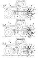
- the actuating lever 6 can by rotation of the Drive shaft 8 are brought into two positions, namely in a first, front Position shown in Fig. 1 and Fig. 6, and a second, rear position, the Fig. 3 and Fig. 4 is shown. In the first, forward position, the operating lever runs 6 at an angle of about 30 ° forward. In the second, rear Position, the actuating lever 6 extends substantially vertically upward.
- a holder 9 is pivotally mounted on the base 3.
- the holder 9 has journals 10, which are mounted in slots 11 pivotally and longitudinally displaceable.
- the base 3 in its lower front region down pointing projections 12, of which in the drawing figures only one is shown; the other is parallel and spaced apart from the drawing plane.
- a slot 11 is provided in each case, which has a slope in the direction from the front bottom to the back top.
- the holder 9 further comprises two longitudinal, horizontal, horizontal parallel, spaced longitudinal strips 13, which by a transverse bar 14 with each other are connected.
- the cross bar 14 has in its center a rear facing, essentially horizontal projection, at the end of a coupling pin 15 sticks up.
- the holder 9 comprises a substantially horizontal and transverse to the vehicle longitudinal direction locking rod 16.
- the holder 9 is also provided on one side with an upwardly facing operating handle 17.
- the holder 9 can be brought into a coupling position, for example, in Figures 4 to 6 and in which the upper end of the coupling pin 15 is very close to the lower end surface of the base 3 or touched. In this position passes through the coupling pin 15, the opening of the drawbar of the Trailer (not shown in the drawings) and holds them reliably.
- the holder 9 can also be brought into a release position, for example is shown in Figures 1 to 3 and in which the coupling pin 15 after is lowered down. In this position, the opening of the drawbar (in the drawing not shown) released. The distance between the top of the Hinge pin 15 and the lower end surface of the base 3 is so large that the Tiller (not shown in the drawing) are pulled backwards can.
- the slider 4 has at its upper side in the region of its rear end a Detent recess 18 for the locking rod 16 of the holder 9.
- the detent recess 18 is from a rear (in the representation of the figures: right) flank, which is essentially vertically, and from a front (in the illustration of the figures: left) edge, which runs approximately vertically.
- the clutch 2 can motor, so by the drive of the servo motor 7, operated become.
- the servo motor 7 can in turn be operated by a remote control.
- the starting position is shown in FIG. 3.
- the operating lever 6 of the servomotor 7 is located in the second, rear position. Accordingly, it is located above the operating rod 5 connected to the upper end of the operating lever 6 slide 4 in the second, rear position.
- the holder 9 is in the release position, in which the coupling pin 15 spaced from the lower surface of the base 3 is.
- the coupling position shown in Fig. 4 can by hand on the intermediate position shown in FIG. 5 in the release position shown in Fig. 3 be transferred.
- the clutch can also be seen from the manually achieved in FIG. 4 coupling position be transferred by the servo motor 7 in a release position. It is also possible, the clutch 2 from that shown in Fig. 1, reached manually Release position to be transferred by the servo motor 7 in a coupling position. This is done as follows:
- the coupling position according to FIG. 6 or the release position according to FIG. 3 independently it is achieved whether the locking rod 16 is located in the locking recess 18 or in one of the two further locking recesses, that is, regardless of whether the existing position of the holder 9 by an operation of the servo motor 7 or can be achieved by hand, the following procedure for the control of the servomotor 7, when the servo motor 7 contains a control command, who is to put him in a position that depends on his present position deviates, it is sufficient that the servo motor 7 is brought into the new position. However, if the servo motor 7 is to be brought into a position in which he is already located, it is first placed in the other position and then back to the position in which he first found himself.
- the Coupling position corresponds, and when it is brought into the release position is, it is sufficient if he carries out a movement that the operating lever 6 of the first, front position in the second, rear position brings.
- the release position achieved according to FIG. 3.
- the clutch 2 is in the position shown in FIG. 1 has, the release position shown in FIG. 3 is also achieved.
- the control proceeds in an analogous manner when the servomotor 7 in the in Fig. 3 shown position corresponding to the release position, and the command receives the release order. Then, the operation lever 6 first brought into the first, front position and then back into the second, rear position.
- the clutch 2 in the position shown in Fig. 3 has been found, first the position shown in FIG. 6 is taken and then again the release position according to FIG. 3.
- the clutch 2 in the hand-held position shown in Fig. 4 it first becomes transferred into the position shown in FIG. 6 and then in the position shown in Fig. 3 End position, namely the release position, brought.
- the servomotor 7 may be destroyed is when the toy model tractor 1 accidentally dropped and on the clutch falls.
- the coupling rod 16 has through the slot 11 a possibility of movement, the destruction of components of the clutch 2 or the Servomotor 7 can prevent.
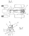
- Fig. 7 shows a modification in which the drive shaft 8 'of the servomotor 7 is not horizontally, but runs in a vertical direction.
- a Operating lever 6 ' is connected, which is horizontal and transverse to the vehicle longitudinal direction extends.
- the Operating lever 6 ' by a rotation of the drive shaft 8' in two positions brought into a first, forward position, which is shown in Fig. 7, and in a second, rear position (not shown in Fig. 7).
- the actuating rod 5 is connected, which in turn is connected to the slider 4 is.
- Fig. 8 shows a modified embodiment of the coupling.
- the Projections 12 of the base 3 bearing pin 10 ' which are aligned with each other and the facing each other.
- a slot 11 ' which has a slope in the direction from the front bottom to the rear has up.
- the pin 10 ' can also be used a clamping sleeve.
Landscapes
- Toys (AREA)
Abstract
Description
- Fig. 1
- einen Spielzeugmodell-Traktor mit einer Kupplung in einer Seitenansicht, teilweise im Schnitt, wobei sich der Halter der Kupplung in der Freigabestellung befindet,
- Fig. 2
- den Spielzeugmodell-Traktor gemäß Fig. 1, wobei sich die Kupplung in einer Zwischenstellung befindet,
- Fig. 3
- den Spielzeugmodell-Traktor gemäß Fig. 1 und 2, wobei sich die Kupplung in der Freigabestellung befindet,
- Fig. 4
- den Spielzeugmodell-Traktor gemäß Fig. 1 bis 3, wobei sich der Halter der Kupplung in der Kupplungsstellung befindet,
- Fig. 5
- den Spielzeugmodell-Traktor gemäß Fig. 1 bis 4, wobei sich die Kupplung in einer Zwischenstellung befindet,
- Fig. 6
- den Spielzeugmodell-Traktor gemäß Fig. 1 bis 5, wobei sich der Halter der Kupplung in der Kupplungsstellung befindet,
- Fig. 7
- eine Abwandlung des Spielzeugmodell-Traktors gemäß Fig. 1 bis 6 in einer Ansicht von oben und
- Fig. 8
- eine Abwandlung der Kupplung in einer Seitenansicht.
Claims (8)
- Kupplung für ein Spielzeugmodell-Fahrzeug
mit einem Sockel (3),
an dem ein Schieber (4) gelagert ist, der durch einen Antrieb (7, 8, 6, 5) in eine erste Stellung und in eine zweite Stellung bringbar ist,
und an dem ein Halter (9) gelagert ist, der einen Kupplungszapfen (15) und eine Raststange (16) aufweist und der in eine Kupplungsstellung und in eine Freigabestellung bringbar ist,
wobei der Schieber (4) eine Rastvertiefung (18) für die Raststange (16) des Halters (9) aufweist. - Kupplung nach Anspruch 1, dadurch gekennzeichnet, daß der Schieber (4) eine zur Rastvertiefung (18) hin verlaufende Anlaufschräge (19) aufweist.
- Kupplung nach Anspruch 1 oder 2, dadurch gekennzeichnet, daß der Schieber (4) eine zur Rastvertiefung (18) hin verlaufende, der Anlaufschräge (19) gegenüberliegende weitere Anlaufschräge (20) aufweist.
- Kupplung nach einem der vorhergehenden Ansprüche, dadurch gekennzeichnet, daß der Schieber (4) längsverschieblich gelagert ist.
- Kupplung nach einem der vorhergehenden Ansprüche, dadurch gekennzeichnet, daß der Halter (9) um einen Lagerzapfen (10, 10') schwenkbar gelagert ist.
- Kupplung nach Anspruch 5, dadurch gekennzeichnet, daß der Lagerzapfen (10, 10') in einem Langloch (11, 11') längsverschieblich gelagert ist.
- Kupplung nach einem der vorhergehenden Ansprüche, dadurch gekennzeichnet, daß der Schieber (4) durch eine Betätigungsstange (5) bewegbar ist.
- Spielzeugmodell-Fahrzeug, gekennzeichnet durch eine Kupplung nach einem der Ansprüche 1 bis 7.
Applications Claiming Priority (4)
| Application Number | Priority Date | Filing Date | Title |
|---|---|---|---|
| DE102004021383 | 2004-04-30 | ||
| DE102004021383 | 2004-04-30 | ||
| DE102004041190A DE102004041190B3 (de) | 2004-04-30 | 2004-08-25 | Kupplung für ein Spielzeugmodell-Fahrzeug |
| DE102004041190 | 2004-08-25 |
Publications (2)
| Publication Number | Publication Date |
|---|---|
| EP1591152A1 true EP1591152A1 (de) | 2005-11-02 |
| EP1591152B1 EP1591152B1 (de) | 2007-06-13 |
Family
ID=34934477
Family Applications (1)
| Application Number | Title | Priority Date | Filing Date |
|---|---|---|---|
| EP05006433A Expired - Lifetime EP1591152B1 (de) | 2004-04-30 | 2005-03-23 | Kupplung für ein Spielzeugmodell-Fahrzeug |
Country Status (5)
| Country | Link |
|---|---|
| EP (1) | EP1591152B1 (de) |
| AT (1) | ATE364430T1 (de) |
| DE (1) | DE502005000839D1 (de) |
| DK (1) | DK1591152T3 (de) |
| ES (1) | ES2287829T3 (de) |
Citations (4)
| Publication number | Priority date | Publication date | Assignee | Title |
|---|---|---|---|---|
| GB525046A (en) * | 1938-10-22 | 1940-08-20 | Ernst Voelk | Improvements in or connected with toy electric railways |
| US5423439A (en) * | 1993-02-03 | 1995-06-13 | Ernst Paul Lehmann Patentwerk | Remote-controlled uncoupling for electric toy and model trains |
| DE19851357A1 (de) * | 1997-11-06 | 1999-10-14 | Joachim Danger | Ferngesteuertes Fahrzeug, insbesondere funkferngesteuertes Modellfahrzeug |
| US6095351A (en) * | 1997-05-02 | 2000-08-01 | Roessler; Elfriede | Coupling device for model railway |
-
2005
- 2005-03-23 AT AT05006433T patent/ATE364430T1/de active
- 2005-03-23 EP EP05006433A patent/EP1591152B1/de not_active Expired - Lifetime
- 2005-03-23 DK DK05006433T patent/DK1591152T3/da active
- 2005-03-23 ES ES05006433T patent/ES2287829T3/es not_active Expired - Lifetime
- 2005-03-23 DE DE502005000839T patent/DE502005000839D1/de not_active Expired - Lifetime
Patent Citations (4)
| Publication number | Priority date | Publication date | Assignee | Title |
|---|---|---|---|---|
| GB525046A (en) * | 1938-10-22 | 1940-08-20 | Ernst Voelk | Improvements in or connected with toy electric railways |
| US5423439A (en) * | 1993-02-03 | 1995-06-13 | Ernst Paul Lehmann Patentwerk | Remote-controlled uncoupling for electric toy and model trains |
| US6095351A (en) * | 1997-05-02 | 2000-08-01 | Roessler; Elfriede | Coupling device for model railway |
| DE19851357A1 (de) * | 1997-11-06 | 1999-10-14 | Joachim Danger | Ferngesteuertes Fahrzeug, insbesondere funkferngesteuertes Modellfahrzeug |
Also Published As
| Publication number | Publication date |
|---|---|
| DK1591152T3 (da) | 2007-07-16 |
| ATE364430T1 (de) | 2007-07-15 |
| DE502005000839D1 (de) | 2007-07-26 |
| ES2287829T3 (es) | 2007-12-16 |
| EP1591152B1 (de) | 2007-06-13 |
Similar Documents
| Publication | Publication Date | Title |
|---|---|---|
| DE102006033899B4 (de) | Steckerkonsole für einen Auflieger eines Sattelzuges | |
| DE102014116000A1 (de) | Anhängevorrichtung für Kraftfahrzeuge | |
| EP1535765B1 (de) | Anhängerkupplung | |
| DE102010000786A1 (de) | Anhängekupplung | |
| EP3348762A1 (de) | Lösbare scharnieranordnung mit fehlbediensperre | |
| DE4135795A1 (de) | Sattelzug stichwort: multikupplung fuer sattelauflieger | |
| DE60213202T2 (de) | Öffnungsfähige Dachkonstruktion für ein Fahrzeug und Verfahren für die Betätigung eines zugehörigen Schliesselementes | |
| DE3239948C1 (de) | Vorrichtung zum Betaetigen eines Schieberverschlusses | |
| DE2931656A1 (de) | Zugkupplung fuer einen traktor | |
| DE3416485A1 (de) | Ausstelldach fuer ein fahrzeug | |
| DE10243433A1 (de) | Anhängerkupplung | |
| EP0529427A1 (de) | Anhängevorrichtung mit Zugpendel | |
| EP0210426B1 (de) | Fernbetätigungsvorrichtung | |
| EP2181868B1 (de) | Anhängekupplung | |
| DE102008018738A1 (de) | Fahrzeugseitige Kupplungsbaugruppe einer Anhängerkupplung | |
| DE102004041190B3 (de) | Kupplung für ein Spielzeugmodell-Fahrzeug | |
| EP1591152B1 (de) | Kupplung für ein Spielzeugmodell-Fahrzeug | |
| DE10105847B4 (de) | Mitnahmevorrichtung für ausziehbaren Möbelboden | |
| DE2638483C3 (de) | Vorrichtung zur Fernbedienung der Verriegelungseinrichtung einer selbsttätigen Anhangerkupplung | |
| DE4310742A1 (de) | Vorrichtung zum Ankuppeln landwirtschaftlicher, verfahrbarer Anbaumaschinen an Schlepper | |
| DE69707977T2 (de) | Automatische Anhängervorrichtung für Fahrzeuge, insbesondere für Landwirtschaftsfahrzeuge | |
| DE2710542C2 (de) | Absperrpfosten zum Absperren eines Abstellplatzes für Kraftfahrzeuge | |
| DE2263839B2 (de) | Verriegelungsvorrichtung zum lösbaren Verbinden des Mähtisches am Schrägförderkanal eines Mähdreschers | |
| DE2712960C3 (de) | Kupplungsvorrichtung für landwirtschaftliche Anhängegeräte | |
| EP0133637A1 (de) | Frontseitige Geräteanbauvorrichtung für ein frontverkleidetes land- und/oder bauwirtschaftlich nutzbares Kraftfahrzeug, insbesondere Ackerschlepper |
Legal Events
| Date | Code | Title | Description |
|---|---|---|---|
| PUAI | Public reference made under article 153(3) epc to a published international application that has entered the european phase |
Free format text: ORIGINAL CODE: 0009012 |
|
| AK | Designated contracting states |
Kind code of ref document: A1 Designated state(s): AT BE BG CH CY CZ DE DK EE ES FI FR GB GR HU IE IS IT LI LT LU MC NL PL PT RO SE SI SK TR |
|
| AX | Request for extension of the european patent |
Extension state: AL BA HR LV MK YU |
|
| 17P | Request for examination filed |
Effective date: 20051219 |
|
| AKX | Designation fees paid |
Designated state(s): AT BE BG CH CY CZ DE DK EE ES FI FR GB GR HU IE IS IT LI LT LU MC NL PL PT RO SE SI SK TR |
|
| GRAP | Despatch of communication of intention to grant a patent |
Free format text: ORIGINAL CODE: EPIDOSNIGR1 |
|
| GRAS | Grant fee paid |
Free format text: ORIGINAL CODE: EPIDOSNIGR3 |
|
| GRAA | (expected) grant |
Free format text: ORIGINAL CODE: 0009210 |
|
| AK | Designated contracting states |
Kind code of ref document: B1 Designated state(s): AT BE BG CH CY CZ DE DK EE ES FI FR GB GR HU IE IS IT LI LT LU MC NL PL PT RO SE SI SK TR |
|
| REG | Reference to a national code |
Ref country code: GB Ref legal event code: FG4D Free format text: NOT ENGLISH |
|
| REG | Reference to a national code |
Ref country code: CH Ref legal event code: EP Ref country code: CH Ref legal event code: NV Representative=s name: BOVARD AG PATENTANWAELTE |
|
| REG | Reference to a national code |
Ref country code: SE Ref legal event code: TRGR |
|
| REG | Reference to a national code |
Ref country code: IE Ref legal event code: FG4D Free format text: LANGUAGE OF EP DOCUMENT: GERMAN |
|
| REG | Reference to a national code |
Ref country code: DK Ref legal event code: T3 |
|
| REF | Corresponds to: |
Ref document number: 502005000839 Country of ref document: DE Date of ref document: 20070726 Kind code of ref document: P |
|
| REG | Reference to a national code |
Ref country code: HU Ref legal event code: AG4A Ref document number: E001815 Country of ref document: HU |
|
| GBT | Gb: translation of ep patent filed (gb section 77(6)(a)/1977) |
Effective date: 20070829 |
|
| ET | Fr: translation filed | ||
| PG25 | Lapsed in a contracting state [announced via postgrant information from national office to epo] |
Ref country code: PL Free format text: LAPSE BECAUSE OF FAILURE TO SUBMIT A TRANSLATION OF THE DESCRIPTION OR TO PAY THE FEE WITHIN THE PRESCRIBED TIME-LIMIT Effective date: 20070613 |
|
| REG | Reference to a national code |
Ref country code: ES Ref legal event code: FG2A Ref document number: 2287829 Country of ref document: ES Kind code of ref document: T3 |
|
| PG25 | Lapsed in a contracting state [announced via postgrant information from national office to epo] |
Ref country code: SI Free format text: LAPSE BECAUSE OF FAILURE TO SUBMIT A TRANSLATION OF THE DESCRIPTION OR TO PAY THE FEE WITHIN THE PRESCRIBED TIME-LIMIT Effective date: 20070613 Ref country code: PT Free format text: LAPSE BECAUSE OF FAILURE TO SUBMIT A TRANSLATION OF THE DESCRIPTION OR TO PAY THE FEE WITHIN THE PRESCRIBED TIME-LIMIT Effective date: 20071113 Ref country code: BG Free format text: LAPSE BECAUSE OF FAILURE TO SUBMIT A TRANSLATION OF THE DESCRIPTION OR TO PAY THE FEE WITHIN THE PRESCRIBED TIME-LIMIT Effective date: 20070913 Ref country code: IS Free format text: LAPSE BECAUSE OF FAILURE TO SUBMIT A TRANSLATION OF THE DESCRIPTION OR TO PAY THE FEE WITHIN THE PRESCRIBED TIME-LIMIT Effective date: 20071013 |
|
| PG25 | Lapsed in a contracting state [announced via postgrant information from national office to epo] |
Ref country code: SK Free format text: LAPSE BECAUSE OF FAILURE TO SUBMIT A TRANSLATION OF THE DESCRIPTION OR TO PAY THE FEE WITHIN THE PRESCRIBED TIME-LIMIT Effective date: 20070613 Ref country code: LT Free format text: LAPSE BECAUSE OF FAILURE TO SUBMIT A TRANSLATION OF THE DESCRIPTION OR TO PAY THE FEE WITHIN THE PRESCRIBED TIME-LIMIT Effective date: 20070613 |
|
| PLBE | No opposition filed within time limit |
Free format text: ORIGINAL CODE: 0009261 |
|
| STAA | Information on the status of an ep patent application or granted ep patent |
Free format text: STATUS: NO OPPOSITION FILED WITHIN TIME LIMIT |
|
| PG25 | Lapsed in a contracting state [announced via postgrant information from national office to epo] |
Ref country code: GR Free format text: LAPSE BECAUSE OF FAILURE TO SUBMIT A TRANSLATION OF THE DESCRIPTION OR TO PAY THE FEE WITHIN THE PRESCRIBED TIME-LIMIT Effective date: 20070914 |
|
| PGFP | Annual fee paid to national office [announced via postgrant information from national office to epo] |
Ref country code: DK Payment date: 20080325 Year of fee payment: 4 Ref country code: ES Payment date: 20080328 Year of fee payment: 4 |
|
| 26N | No opposition filed |
Effective date: 20080314 |
|
| PG25 | Lapsed in a contracting state [announced via postgrant information from national office to epo] |
Ref country code: RO Free format text: LAPSE BECAUSE OF FAILURE TO SUBMIT A TRANSLATION OF THE DESCRIPTION OR TO PAY THE FEE WITHIN THE PRESCRIBED TIME-LIMIT Effective date: 20070613 |
|
| PGFP | Annual fee paid to national office [announced via postgrant information from national office to epo] |
Ref country code: CZ Payment date: 20080303 Year of fee payment: 4 Ref country code: HU Payment date: 20080307 Year of fee payment: 4 Ref country code: IE Payment date: 20080326 Year of fee payment: 4 Ref country code: LU Payment date: 20080326 Year of fee payment: 4 Ref country code: SE Payment date: 20080320 Year of fee payment: 4 |
|
| PGFP | Annual fee paid to national office [announced via postgrant information from national office to epo] |
Ref country code: BE Payment date: 20080325 Year of fee payment: 4 |
|
| PG25 | Lapsed in a contracting state [announced via postgrant information from national office to epo] |
Ref country code: MC Free format text: LAPSE BECAUSE OF NON-PAYMENT OF DUE FEES Effective date: 20080331 |
|
| PG25 | Lapsed in a contracting state [announced via postgrant information from national office to epo] |
Ref country code: EE Free format text: LAPSE BECAUSE OF FAILURE TO SUBMIT A TRANSLATION OF THE DESCRIPTION OR TO PAY THE FEE WITHIN THE PRESCRIBED TIME-LIMIT Effective date: 20070613 |
|
| PG25 | Lapsed in a contracting state [announced via postgrant information from national office to epo] |
Ref country code: FI Free format text: LAPSE BECAUSE OF FAILURE TO SUBMIT A TRANSLATION OF THE DESCRIPTION OR TO PAY THE FEE WITHIN THE PRESCRIBED TIME-LIMIT Effective date: 20070613 |
|
| PG25 | Lapsed in a contracting state [announced via postgrant information from national office to epo] |
Ref country code: CY Free format text: LAPSE BECAUSE OF FAILURE TO SUBMIT A TRANSLATION OF THE DESCRIPTION OR TO PAY THE FEE WITHIN THE PRESCRIBED TIME-LIMIT Effective date: 20070613 |
|
| BERE | Be: lapsed |
Owner name: SIEPER WERKE G.M.B.H. Effective date: 20090331 |
|
| PG25 | Lapsed in a contracting state [announced via postgrant information from national office to epo] |
Ref country code: CZ Free format text: LAPSE BECAUSE OF NON-PAYMENT OF DUE FEES Effective date: 20090323 |
|
| REG | Reference to a national code |
Ref country code: CH Ref legal event code: PL |
|
| REG | Reference to a national code |
Ref country code: DK Ref legal event code: EBP |
|
| EUG | Se: european patent has lapsed | ||
| PG25 | Lapsed in a contracting state [announced via postgrant information from national office to epo] |
Ref country code: IE Free format text: LAPSE BECAUSE OF NON-PAYMENT OF DUE FEES Effective date: 20090323 Ref country code: HU Free format text: LAPSE BECAUSE OF NON-PAYMENT OF DUE FEES Effective date: 20090324 Ref country code: CH Free format text: LAPSE BECAUSE OF NON-PAYMENT OF DUE FEES Effective date: 20090331 Ref country code: LI Free format text: LAPSE BECAUSE OF NON-PAYMENT OF DUE FEES Effective date: 20090331 |
|
| PG25 | Lapsed in a contracting state [announced via postgrant information from national office to epo] |
Ref country code: BE Free format text: LAPSE BECAUSE OF NON-PAYMENT OF DUE FEES Effective date: 20090331 |
|
| PG25 | Lapsed in a contracting state [announced via postgrant information from national office to epo] |
Ref country code: DK Free format text: LAPSE BECAUSE OF NON-PAYMENT OF DUE FEES Effective date: 20090331 |
|
| REG | Reference to a national code |
Ref country code: ES Ref legal event code: FD2A Effective date: 20090324 |
|
| PG25 | Lapsed in a contracting state [announced via postgrant information from national office to epo] |
Ref country code: ES Free format text: LAPSE BECAUSE OF NON-PAYMENT OF DUE FEES Effective date: 20090324 |
|
| PG25 | Lapsed in a contracting state [announced via postgrant information from national office to epo] |
Ref country code: TR Free format text: LAPSE BECAUSE OF FAILURE TO SUBMIT A TRANSLATION OF THE DESCRIPTION OR TO PAY THE FEE WITHIN THE PRESCRIBED TIME-LIMIT Effective date: 20070613 |
|
| PG25 | Lapsed in a contracting state [announced via postgrant information from national office to epo] |
Ref country code: LU Free format text: LAPSE BECAUSE OF NON-PAYMENT OF DUE FEES Effective date: 20090323 |
|
| PG25 | Lapsed in a contracting state [announced via postgrant information from national office to epo] |
Ref country code: SE Free format text: LAPSE BECAUSE OF NON-PAYMENT OF DUE FEES Effective date: 20090324 |
|
| PGFP | Annual fee paid to national office [announced via postgrant information from national office to epo] |
Ref country code: IT Payment date: 20080331 Year of fee payment: 4 |
|
| REG | Reference to a national code |
Ref country code: DE Ref legal event code: R082 Ref document number: 502005000839 Country of ref document: DE Representative=s name: RECHTS- UND PATENTANWAELTE LORENZ SEIDLER GOSS, DE |
|
| REG | Reference to a national code |
Ref country code: DE Ref legal event code: R082 Ref document number: 502005000839 Country of ref document: DE Representative=s name: RECHTS- UND PATENTANWAELTE LORENZ SEIDLER GOSS, DE Effective date: 20121107 Ref country code: DE Ref legal event code: R081 Ref document number: 502005000839 Country of ref document: DE Owner name: SIEPER LUEDENSCHEID GMBH & CO. KG, DE Free format text: FORMER OWNER: SIEPER-WERKE GMBH, 58511 LUEDENSCHEID, DE Effective date: 20121107 Ref country code: DE Ref legal event code: R082 Ref document number: 502005000839 Country of ref document: DE Representative=s name: LORENZ SEIDLER GOSSEL RECHTSANWAELTE PATENTANW, DE Effective date: 20121107 |
|
| REG | Reference to a national code |
Ref country code: FR Ref legal event code: TP Owner name: SIEPER LUDENSCHEID GMBH & CO. KG, DE Effective date: 20130122 |
|
| REG | Reference to a national code |
Ref country code: GB Ref legal event code: 732E Free format text: REGISTERED BETWEEN 20130215 AND 20130220 |
|
| REG | Reference to a national code |
Ref country code: NL Ref legal event code: TD Effective date: 20130311 Ref country code: NL Ref legal event code: SD Effective date: 20130311 |
|
| REG | Reference to a national code |
Ref country code: AT Ref legal event code: PC Ref document number: 364430 Country of ref document: AT Kind code of ref document: T Owner name: SIEPER LUEDENSCHEID GMBH & CO. KG, DE Effective date: 20130920 |
|
| REG | Reference to a national code |
Ref country code: FR Ref legal event code: PLFP Year of fee payment: 12 |
|
| REG | Reference to a national code |
Ref country code: FR Ref legal event code: PLFP Year of fee payment: 13 |
|
| REG | Reference to a national code |
Ref country code: FR Ref legal event code: PLFP Year of fee payment: 14 |
|
| PGFP | Annual fee paid to national office [announced via postgrant information from national office to epo] |
Ref country code: NL Payment date: 20220630 Year of fee payment: 18 Ref country code: GB Payment date: 20220630 Year of fee payment: 18 |
|
| PGFP | Annual fee paid to national office [announced via postgrant information from national office to epo] |
Ref country code: AT Payment date: 20220706 Year of fee payment: 18 |
|
| PGFP | Annual fee paid to national office [announced via postgrant information from national office to epo] |
Ref country code: FR Payment date: 20220630 Year of fee payment: 18 |
|
| PGFP | Annual fee paid to national office [announced via postgrant information from national office to epo] |
Ref country code: DE Payment date: 20220714 Year of fee payment: 18 |
|
| REG | Reference to a national code |
Ref country code: DE Ref legal event code: R119 Ref document number: 502005000839 Country of ref document: DE |
|
| REG | Reference to a national code |
Ref country code: NL Ref legal event code: MM Effective date: 20230401 |
|
| REG | Reference to a national code |
Ref country code: AT Ref legal event code: MM01 Ref document number: 364430 Country of ref document: AT Kind code of ref document: T Effective date: 20230323 |
|
| GBPC | Gb: european patent ceased through non-payment of renewal fee |
Effective date: 20230323 |
|
| PG25 | Lapsed in a contracting state [announced via postgrant information from national office to epo] |
Ref country code: NL Free format text: LAPSE BECAUSE OF NON-PAYMENT OF DUE FEES Effective date: 20230401 |
|
| PG25 | Lapsed in a contracting state [announced via postgrant information from national office to epo] |
Ref country code: GB Free format text: LAPSE BECAUSE OF NON-PAYMENT OF DUE FEES Effective date: 20230323 |
|
| PG25 | Lapsed in a contracting state [announced via postgrant information from national office to epo] |
Ref country code: GB Free format text: LAPSE BECAUSE OF NON-PAYMENT OF DUE FEES Effective date: 20230323 Ref country code: FR Free format text: LAPSE BECAUSE OF NON-PAYMENT OF DUE FEES Effective date: 20230331 Ref country code: DE Free format text: LAPSE BECAUSE OF NON-PAYMENT OF DUE FEES Effective date: 20231003 Ref country code: AT Free format text: LAPSE BECAUSE OF NON-PAYMENT OF DUE FEES Effective date: 20230323 |