EP1591174A1 - Dispositif de pliage pour des pièces en forme de barre ou de tube - Google Patents
Dispositif de pliage pour des pièces en forme de barre ou de tube Download PDFInfo
- Publication number
- EP1591174A1 EP1591174A1 EP04007328A EP04007328A EP1591174A1 EP 1591174 A1 EP1591174 A1 EP 1591174A1 EP 04007328 A EP04007328 A EP 04007328A EP 04007328 A EP04007328 A EP 04007328A EP 1591174 A1 EP1591174 A1 EP 1591174A1
- Authority
- EP
- European Patent Office
- Prior art keywords
- bending
- mandrel
- clamping
- groove
- workpiece
- Prior art date
- Legal status (The legal status is an assumption and is not a legal conclusion. Google has not performed a legal analysis and makes no representation as to the accuracy of the status listed.)
- Granted
Links
- 238000005452 bending Methods 0.000 title claims abstract description 192
- 230000033001 locomotion Effects 0.000 claims description 33
- 238000011144 upstream manufacturing Methods 0.000 claims description 7
- 238000009499 grossing Methods 0.000 claims description 4
- 238000000465 moulding Methods 0.000 claims description 4
- 238000003825 pressing Methods 0.000 claims description 4
- 230000037303 wrinkles Effects 0.000 description 9
- 238000000034 method Methods 0.000 description 7
- 239000000463 material Substances 0.000 description 5
- 230000008569 process Effects 0.000 description 5
- 238000006073 displacement reaction Methods 0.000 description 4
- 230000005540 biological transmission Effects 0.000 description 3
- 238000005336 cracking Methods 0.000 description 3
- 238000003780 insertion Methods 0.000 description 3
- 230000037431 insertion Effects 0.000 description 3
- 230000003993 interaction Effects 0.000 description 3
- 244000089486 Phragmites australis subsp australis Species 0.000 description 2
- 230000008859 change Effects 0.000 description 2
- 238000006243 chemical reaction Methods 0.000 description 2
- 230000012447 hatching Effects 0.000 description 2
- 241000792859 Enema Species 0.000 description 1
- 230000008901 benefit Effects 0.000 description 1
- 230000015572 biosynthetic process Effects 0.000 description 1
- 230000003750 conditioning effect Effects 0.000 description 1
- 238000010276 construction Methods 0.000 description 1
- 238000005520 cutting process Methods 0.000 description 1
- 230000000694 effects Effects 0.000 description 1
- 239000007920 enema Substances 0.000 description 1
- 229940095399 enema Drugs 0.000 description 1
- 230000010354 integration Effects 0.000 description 1
- 238000003754 machining Methods 0.000 description 1
- 230000007246 mechanism Effects 0.000 description 1
- 238000013000 roll bending Methods 0.000 description 1
- 238000004804 winding Methods 0.000 description 1
Images





Classifications
-
- B—PERFORMING OPERATIONS; TRANSPORTING
- B21—MECHANICAL METAL-WORKING WITHOUT ESSENTIALLY REMOVING MATERIAL; PUNCHING METAL
- B21D—WORKING OR PROCESSING OF SHEET METAL OR METAL TUBES, RODS OR PROFILES WITHOUT ESSENTIALLY REMOVING MATERIAL; PUNCHING METAL
- B21D7/00—Bending rods, profiles, or tubes
- B21D7/02—Bending rods, profiles, or tubes over a stationary forming member; by use of a swinging forming member or abutment
- B21D7/024—Bending rods, profiles, or tubes over a stationary forming member; by use of a swinging forming member or abutment by a swinging forming member
Definitions
- the invention relates to a bending device for rod and tubular workpieces, wherein the bending device comprises a bending head with a mounted on a rotation axis, by means of a rotary drive rotatable mandrel and with a clamping device for Pressing of the workpiece to be bent against a forming groove on the mandrel comprises, wherein the Bending head further comprises a feed device for the workpiece to be machined and the Clamping device movable relative to the mandrel and 'concentric with the axis of rotation of the Bending mandrel is pivotable.
- Such bending devices are used in modern bending machines for rod-like workpieces and used for prefabricated cables with mainly larger cross sections.
- the bending device is composed of several units, which especially in tubular workpieces with thin wall thicknesses by their interaction a good Allow bending result.
- a bending device should ideally meet a number of specific requirements be able to perform the following functions: Left and Right bending, pull and roll bending, winding, a bend without intermediate straight Create piece directly after another bend, make different bending radii, bend different pipe diameters, prevent wrinkles, bend in three dimensions and allow easy conversion.
- Bending devices with bending heads are known which are suitable for changing over from left to right Legal winds z. B. must be rotated (see, EP 1 226 887 B1, EP 1 291 094 B1 and EP 1 350 578 A1) or which are constructed symmetrically (WO 03/053 606 A1). Likewise is too the possibility of changing a bending head for such a change known.
- WO 2004/000479 A1 describes a bending device of the type mentioned, which can be used for both left and right bending, without causing the Bending mandrel would have to be replaced. This is formed substantially circular and with two axially mutually offset from him, circular shape grooves one of which is used for left-hand bending and the other for right-hand bending.
- the tube becomes again between clamping device and bending mandrel (there again in one on the other Formnut appropriately attached fitting with a rectilinear, tangential from the forming groove of the bending mandrel outgoing Formnutabites) braced and then by a common rotation of the clamping device and mandrel around the Rotational axis of the mandrel, this time in the opposite direction of rotation, the new bend on Tube generated.
- the invention is based on the object, such a bending device to improve such that the clamping device with a particularly small footprint gets along and for the linear movement of the clamping device no separate linear adjustment motor is required.
- this is in a bending device of the type mentioned by achieved that the clamping device to two independent rotary actuators is connected, one of them to perform their pivoting movement about the axis of rotation the bending mandrel serves and over the other them with the interposition of a Implementation gear that converts a rotary motion in a linear motion, opposite the mandrel is movable, wherein the mandrel to transfer the drive of the three Rotary drives to the bending mandrel, to the transfer gear and the clamping device three comprises concentrically nested rotary shafts, each of which is connected to one of the rotary drives connected.
- the innermost rotary shaft is arranged at the very top of the bending head Bending mandrel, while, again preferred, the central rotating shaft that at the bending head below the Bending mandrel mounted transfer gear for generating the linear movement for the Clamping device drives, wherein preferably the outer rotary shaft with a below the transfer gear arranged holding plate is rotatably connected, on which the Clamping device is slidably mounted in one direction to the bending mandrel.
- the bending device according to the invention is characterized in that also the linear Adjusting movement of the clamping device of a rotary drive (with the interposition of a Transfer gear) is derived, the possibility created, the three rotary actuators over three concentric with each other to transmit rotary shafts to the desired parts and thereby achieving a particularly compact overall design for the bending head, wherein the Integration of such a transfer gear in the overall structure of the three intertwined Shafts in the context of the bending head can be easily realized. The need for Using a separate, extra outside to be arranged linear drive is avoided.
- the control of the motors for the three rotary actuators z. B.
- the setting is a desired one Pressing force with which the clamping device the wire against the forming groove in the mandrel presses, problem-free possible.
- the transfer gear comprises a grooved disc with a in this trained, eccentric to its axis of rotation groove into which a at the Clamping device fixed, the cross-sectional shape of the groove corresponding shaped body engages, which is displaceable in the groove and its distance from the axis of rotation of the Nutenusion is variable by a rotation of the Nutenusion.
- This can be done as part of a Art Slotted guide by the rotational movement of the grooved disc quickly a corresponding linear Adjusting movement of the clamping device can be effected, the drive not only very is ptatzquaintd, but the adjustment movements are also carried out very quickly can.
- the clamping device preferably has a non-rotatable on the Nutenin with this fastened mounting device and a clamping bracket, which in a on the Mounting device mounted linear guide slidably mounted and on which in the Groove in the Nutenin engaging moldings is attached.
- the clamping block with a replaceable attached to it Provided clamping jaws, in which one of the position of the forming groove in the bending head accordingly arranged, the shape of the workpiece to be clamped adapted shape groove is attached.
- the shape of the Form groove at a change of the workpiece to be bent whose changed Mold dimensions are adjusted.
- the clamping block is mounted on a support member, which carries the molded body and is above this in engagement with the linear guide, wherein, again Preferably, this support member in turn sits on a support member on which it is in a Direction perpendicular to the orientation of the linear guide adjustably mounted and on the Shaped body is mounted for sliding engagement with the linear guide. Particularly preferred while the support member on the support member to adjust against this to a Drive device connected.
- a bending device when the Clamping device, seen in the feed direction of the workpiece, nor a wrinkle smoother is immediately upstream, through which a wrinkling on the to be bent Workpiece just in the bend upstream workpiece area can be avoided. This prevents that to be bent z.
- a program control device For controlling the three different rotary drives and possibly further Drive devices (eg., For adjusting the support member on the support member) is advantageously provided a program control device.
- Another preferred embodiment of the bending device according to the invention consists also in that a further drive means is provided, through which the bending head in two mutually perpendicular, in each case to the feed direction of the workpiece to be bent in turn vertical directions is moved, which gives the possibility of the bending head under held by a chuck and projecting from this pipe (possibly already with a bend at its one end) down to below, below the same on its other side over and then back up to the workpiece bend in the other bending direction, in which case only the Tensioning device swung 180 ° and also the bending mandrel with the on his opposite side mounted mold groove in correct orientation to him then facing tube side must be spent.
- a further advantageous embodiment of the bending device according to the invention also exists in that on the side of the workpiece on which the clamping device is arranged, this instead of a Faltenglätters a stationary mounted guide roller for the workpiece upstream, which may be arranged so that they, if desired, with a can press against the corresponding side of the workpiece certain pressure.
- a preferred embodiment of the invention is also that the Bending mandrel as well as the clamping jaws of the clamping block each in the form of a roll with a Guide groove for abutment against the facing side of the workpiece to be bent is formed, resulting in a simplified design again the inventive bending device results in a particularly compact design.
- the wrinkle smoother at least two in the feed direction of the bending Workpiece has successively arranged pressure rollers (instead of the sliders), then is thus created a bending device according to the invention, with which it is possible, even in the Wind method to produce the desired bend.
- the bending radius produced on the workpiece by the Clamping device can be continuously changed, thus producing a elliptical, oval or spiral bends is possible.
- the bending device may be any suitable form of a bending mandrel be used, such. B. in the form of a circular roller with a corresponding circumferential Shaped groove.
- the bending mandrel is designed so that it, parallel to seen from its pivot axis, a non-rotationally symmetrical, but to a vertical lying to the axis of rotation and extending through this central axis symmetrical shape having, attached to the mandrel forming groove for abutment against one side of the bending workpiece, seen relative to this longitudinal central axis, on both sides of the bending mandrel also symmetrical to each other.
- Such a configuration gives a special preferably usable mandrel, which is not about when changing the bending direction 180 °, but only has to be rotated by a small angle.
- the inventive bending device of very compact and space-saving design can be readily used for a right as well as for a left bend, wherein always also the advantage is given that the rotary shafts for mandrel, transfer gear and Clamping the corresponding movements of these individual facilities by pure Rotary movements, in addition to an identical central axis (because of the concentric can cause transmission waves arranged to each other). This allows one especially fast and precise control of the individual movements independently from each other.
- the bending device according to the invention is very compact and allows a large Bend freedom, namely both small distances between successive bends as even small distances of the bends from the ends of the prefabricated pipe workpieces, whereby a gentle material treatment can be ensured.
- the many realized in the invention degrees of freedom Device allow optimal adjustability to the particular circumstances, such.
- Figures 1 to 12 relate to a first, particularly advantageous embodiment of a bending device, while in Fig. 13 (in oblique perspective view) another embodiment for a bending head in a Such a bending device and in Fig. 14 is a basic plan view of one another Embodiment for a bending head is shown. It will be in all figures, even so far they relate to modified embodiments, the same reference numerals for the same parts used.
- Figures 1 to 12 is a first embodiment of a Represent bending device.
- FIG. 1 shows a perspective view (obliquely from the top front) on a bending device 1 briefly before performing a right bending
- Fig. 12 the same perspective Oblique representation of the same bending device 1 is shown, but in the initial state before a left bend process.
- the bending device 1 comprises essentially three important Means, namely a bending head 2 (with a clamping device 3), further a Slide rail 4 (as feeder) and a fold smoother 5. These three devices serve for producing bends on pre-assembled lines or pipes 6, to a achieve good forming without wrinkling or cracking on the pipe 6.
- the bending device 1 can be moved in its entirety on a horizontal trajectory a and a vertical trajectory b , by means of a suitable (but not shown in the figures) corresponding drive.
- the bending head 2 initially consists of a supporting body 2A, on which a bending mandrel 7 rotatable about a central axis M is arranged on top.
- the side of the mandrel 7 is a tubular workpiece 6 (with relatively small wall thickness) in a bending mandrel mounted there, over three sides of the same extending groove 8, which is adapted in its groove shape of the shape of the tube 6.
- the tube 6 is fed in the direction c by a (not shown in the figures) transport device, from which it exits via a (also not shown in the figures) collet by means of which it can be kept fixed in position in a certain position at any time.
- a transport device from which it exits via a (also not shown in the figures) collet by means of which it can be kept fixed in position in a certain position at any time.
- FIG. 2 sectional view along a Sectional plane which is perpendicular to the longitudinal direction of the supplied pipe 6 and through the axis of rotation M of the bending mandrel 7 extends
- Fig. 2 surrounds in Fig. 2 only with a solid line shown in principle support body 2A an arrangement of three concentric nested rotary shafts 9 ', 10' and 11 ', which run as a running Hollow shafts are formed.
- the three different hatching in Fig. 2 serve to the individual power transmission paths of the three rotary actuators 9, 10, 11 via the associated Rotary shafts 9 ', 10', 11 'to represent the parts to be rotated, each hatching to a parts belonging to a drive train.
- the rotary drive 9 drives directly the rotary shaft 9 ', the tool holder 7' and the on this sitting bending mandrel 7 at.
- the central rotating shaft 10 'of the concentric rotary shaft assembly becomes at its lower End driven by a belt drive 13 by a rotary drive 10 and in turn serves for propelling a groove plate 25 via a rotary flange 10 "attached to it at its top, will be discussed in more detail below.
- the outer rotary shaft 11 'of the concentric rotary shaft assembly is connected via a Belt drive 14 driven by a rotary drive 11.
- a rotary drive 11 At her upper end is at her one rotatable mounting plate 15 is fixed on which a mounting device 16 is mounted and in the a linear guide 17 is formed, which - will be discussed below - the Guiding a linear movement in the direction of the position of the bending mandrel 7 out (or of this way) for a sliding in the linear guide 17 part allowed.
- the bending mandrel 7 is laterally associated with a clamping jaws 18 (cf., Fig. 1 and 2 and in particular the enlarged views of FIGS. 3 and 4), on its the bending mandrel. 7 facing side carries an interchangeable jaws 19, in which (in particular good from Fig. 3 can be seen) facing the tube to be bent 6, a forming groove 28 of the Shape of the tube 6 corresponding size is formed.
- the clamping block 18 with the clamping jaws 19 is mounted on a support member 20, z. B. not with shown screws attached.
- the support member 20 sits in turn on a support member 21 and that in the from Exploded view of Fig. 3 clearly visible manner: on the bottom of the Retaining element 20 is a T-shaped, downwardly open mold groove 22, transverse to Displacement direction of the clamping jaw 18 running, trained, in the one on top of the Support member 21 mounted nut 21 'with a corresponding T-shaped cross-section is positively inserted. This makes it possible, the support member 20 transverse to Move direction of the clamping block 18 on the support member to move laterally to a be able to adjust very specific relative position of the clamping block 18 to the rotary mandrel 7.
- a molded body in the form of a rotatable roller 23rd attached, which projects there and in a corresponding mold groove 27 (see Figures 1 to 4) intervenes.
- This roller 25 sits freely rotatable on an anchored in the support member 21 retaining bolts 26th
- the support member 21 is provided with a shape such that it, in particular the Fig. 2 and there partially cut Fig. 4 show, to its two sides by the there in the support device 16 mounted linear or longitudinal guide 17 is guided and in whose longitudinal direction is displaceable.
- a transfer gear 24 which serves the rotational movement of the rotary shaft 10 ', which serves for the displacement of the clamping device 3, in a linear adjustment movement of the holding part 21 (and thus of the attached thereto Holding element 20 and the clamping block 18 with clamping jaws 19) to effect.
- a fork-shaped cover plate 29 which consists of a front substantially circular Section with a circular inner opening for attachment to the upper end of the Turning flange 10 "and starting from this section with two in the longitudinal direction of Mounting device 16 is provided extending lateral fork legs 30, whose each rests on the top of a respective side part 33 of the support means 16 and about in this fork legs mounted holes 31, which correspond to holes 32nd are assigned on the top of the side parts 33, fixed by means of screws on this become.
- the lateral fork legs 30 of the cover plate 29 are slightly wider than the each underlying upper side of a side part 33 executed and form with the free Gap 30 'between them another longitudinal guide for a stepped upper mold area 21 "of the support member 21, so that the latter in its longitudinal movement in the direction of the Bending mandrel 7 back and from this back both through this gap 30 'between the Fork legs 30, as well as by the mounted in the support means 16 below Longitudinal strips of the linear guide 17 is guided.
- the mounting device 16 is at her from the Rotary mandrel 7 opposite end with a slightly upwards over the side parts 33 projecting Connection plate 34 is provided, which the interior 35, between the side legs 33 and the holding plate 15 is present, in the direction of the bending mandrel 7 off. At the same time, this connecting plate 34 also serves as an end stop for the supporting part 21 in FIG Meaning a maximum extended position.
- each side part 33 On the underside of each side part 33 is a recess 36 mounted, which makes it possible that through them the Nutenprint 25 with the on her formed eccentric groove 27 between the respective side part 33 and the outer Circumference of the rotary flange 10 "25 are passed during rotation of the grooved disc can, as can be seen in detail from Figs. 3 and 4, on the representation thereof is expressly referred to.
- Figures 5 to 7 show now, in a basic plan view of the bending head of the Figures 1 to 4, different processes for producing a 90 ° bend of a Pre-assembled tube 6 with thin wall thickness.
- Fig. 6 shows first the insertion position of the bending device 1, in which the Bending mandrel 7 with its mold groove 8 against the facing side of the supplied pipe. 6 is applied while the chuck 3 from the mandrel 7 and the tube 6 is removed. from Wrinkle smoother 4 are on the side on which the mandrel 7 is located, two guide jaws 38 with also formed on them forming grooves 41 (Fig. 12) in alignment with the mold groove 8 of the Bending mandrel 7 also applied to the workpiece 6, each guide jaw 38, as shown Fig. 1 can be seen, is attached by means of a screw 39 to an associated holder 40.
- a Sliding jaws 37 of the Faltenglätters 4 is provided, which, as shown in FIG. 5, in the loading position as well as the clamping device 3 is moved away from the wire 6.
- the slide rail 4 is mounted on the bending head 2 and contains two Spindle drives 60, 61, via which a plate 62 with the sliding block 37 in a plane can be positioned.
- the slide rail 4 with respect to the axis of the tube 6 is always positioned on the side of the tensioner 18.
- a sliding block 37 is located on the pipe 6.
- the slide 4 during the bending process different Perform functions: it runs z. B. with the tube 8, pulls it back or pushes it, for example, to avoid cracking in the pipe material.
- the slide rail 4 also for positioning the Support member 20 with the clamping block 18 and the clamping jaws 19 and the Pivoting the holder 40 with the guide jaws 38 of the Faltenglätters 5 used.
- the holder 40 of the Faltenglätters 5 with the attached guide jaws 38 is mounted by means of linear guide pairs 63 on the slide rail 4.
- the linear guide pairs 63 are connected to each other via a bridge 64.
- the wrinkle smoother 5 can be moved or adjusted via suitable means (not shown in detail) in the direction of the arrow F (FIG. 1), whereby it can also be rotated relative to the bending mandrel 7 (likewise not shown in detail). As a result, an optimal adjustment of the Faltenglätters 5 can ensure both left and right bending.
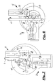
- Figs. 8 to 11 now show, also in a plan view as Figs. 5 to 7, a bend in opposite direction as in Figs. 5 to 7, namely a left turn.
- the bent tube 6 is first held in the position of a (not shown in Fig. 1) collet, which results from Fig. 7. Subsequently, 25 of the clamping jaws 19 is moved away from the mandrel 7 by rotating the Nutenmount; the sliding jaw 37 of the Faltenglätters 5 is also linearly moved away from the wire 6. Subsequently, the pipe section 6 is transported so much and simultaneously rotated by 90 ° upwards (in the direction of rotation d ) that the (previously already bent) pipe end has vertically upwards, as can be seen in the perspective view of FIG. 12 (there but already in the clamped state again).
- the bending head 2 When the tube 6 is released, the bending head 2 is moved away vertically downward (in the direction b ), so that the bending head 2 with the bending mandrel 7 is completely below the out of the collet protruding tube 6, after which, as shown in FIG. 8, the Bending mandrel 7 against the previous bending direction in the direction of rotation w (as indicated in Fig. 8) is pivoted.
- the covered by the pipe 6 parts of the underlying bending head 2 are shown in dashed lines in Figs. 8 to 10.
- FIG. 9 another actuating step is shown, in which now, still lying with the bending head 2 below the pipe section 6, by common, equally fast and rectified rotation of the support plate 15 (with arranged thereon mounting means 16 with the clamping device 3) and Grooved disk 25 by 90 ° (in the direction of rotation y 1 ) in one of the position of the clamping device 3 of FIG. 5 by 180 ° opposite position spent.
- Fig. 10 shows the position which is achieved when the sliding block 37 together with the Clamping device 3 is spent in a position corresponding to the position of Fig. 5, wherein However, the elements each on the opposite side of the position in FIG Tube 6 is present.
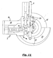
- FIG. 11 shows the starting position of tube 6, clamping device 3, bending mandrel 7 and folding smoother 5 relative to one another for left-hand bending, as corresponds in principle to the starting position for the bending process, corresponding to the position from FIG. 6 for right-hand bending.
- the sliding jaw 37 has been moved from the intermediate position shown in FIG. 10 a little further away from the tube 6, so that overall there is an open insertion position for the tube 6 again.
- the bending head 2 is raised again upward (in the direction of movement b (from FIG. 1)) and then with the bending mandrel 7 and the sliding jaw 37 of the Faltenglätters 5 against the one (in Fig.
- FIG. 11 The initial position reached in FIG. 11 before the bending operation (to the left) is still shown in FIG. 12 once shown in a perspective plan view of the bending device.
- the bending mandrel 7 is, in plan view, not rotationally symmetric, but mirror-symmetrical order one by its axis of rotation (corresponding to the axis of rotation M of the overall arrangement of the three in intersecting rotary shafts 9 ', 10' and 11 ') extending median plane X-X ( "Axis of symmetry").
- the formed on the bending mandrel 7 Formnut 8 extends along the both longitudinal sides of the bending mandrel 7 shown in Fig. 11 and in the region 46, in which the Ends are connected to each other via a circular path, so that a total of three sides of the Bending mandrel 7 throughout the mold groove 8 extends, their shape formation in turn again symmetrical to the median plane X-X.
- This means that the inserted mandrel 7 can work with only a single Formnut 8 and it is not necessary to different Form grooves, even at different axial heights of the mandrel 7, use.
- FIGS. 13 and 14 are again schematic perspective oblique views of two further embodiments of a bending head 2 shown:
- the sliding block 37 of the Faltenglätters 5 is in the embodiment of FIG. 13 by a Guide roller 42 replaced, which is arranged freely rotatable and the pipe to be bent before his Enema into the mold groove 8 of the mandrel 7 leads.
- the bending mandrel 7 consists in principle of a Bending roll, which is not executed over a full circumference, but in the one part of the circumference is cut off, as shown in FIG. 13, to which reference is made.
- the clamping device 3 comprises a clamping jaw 43, the over a holding device 44 shown only in principle in FIG. 13 (in FIG. 13 in the form of a Pin shown), which in a radially extending slot guide 45 (in the form of a Langloches) is formed in the holding plate 15.
- This holding device 44 is below the Retaining plate 15, z. B. in a (not visible) eccentric guide led to the Central axis M of the rotary head 2 for moving the clamping jaw 43 relative to the pipe 6 is guided.
- this eccentric in Fig. 13 not shown in detail
- FIG. 14 differs from FIG the other previously described embodiments in particular in that there instead of the sliding block 37 two guide rollers 47, 48 for lateral contact against the bending pipe 6 provided and the clamping block 3 (in the transport direction c of the pipe. 6 seen) are connected upstream.
- the clamping jaws 19 are no longer provided with a guide groove, such as in the embodiments of the preceding figures, but with a bending roller 49, with the desired deformation of the tube 6 can be performed.
- the mandrel is in this embodiment as a bending roller 50 with a circumferential Form groove designed to rest against the pipe section 6.
Landscapes
- Engineering & Computer Science (AREA)
- Mechanical Engineering (AREA)
- Bending Of Plates, Rods, And Pipes (AREA)
Priority Applications (4)
| Application Number | Priority Date | Filing Date | Title |
|---|---|---|---|
| DE502004007277T DE502004007277D1 (de) | 2004-03-26 | 2004-03-26 | Biegevorrichtung für stab- und rohrförmige Werkstücke |
| EP04007328A EP1591174B1 (fr) | 2004-03-26 | 2004-03-26 | Dispositif de pliage pour des pièces en forme de barre et de tube |
| AT04007328T ATE396799T1 (de) | 2004-03-26 | 2004-03-26 | Biegevorrichtung für stab- und rohrförmige werkstücke |
| US11/088,102 US7234333B2 (en) | 2004-03-26 | 2005-03-23 | Machine for bending rod-shaped or tubular workpieces |
Applications Claiming Priority (1)
| Application Number | Priority Date | Filing Date | Title |
|---|---|---|---|
| EP04007328A EP1591174B1 (fr) | 2004-03-26 | 2004-03-26 | Dispositif de pliage pour des pièces en forme de barre et de tube |
Publications (2)
| Publication Number | Publication Date |
|---|---|
| EP1591174A1 true EP1591174A1 (fr) | 2005-11-02 |
| EP1591174B1 EP1591174B1 (fr) | 2008-05-28 |
Family
ID=34924534
Family Applications (1)
| Application Number | Title | Priority Date | Filing Date |
|---|---|---|---|
| EP04007328A Expired - Lifetime EP1591174B1 (fr) | 2004-03-26 | 2004-03-26 | Dispositif de pliage pour des pièces en forme de barre et de tube |
Country Status (4)
| Country | Link |
|---|---|
| US (1) | US7234333B2 (fr) |
| EP (1) | EP1591174B1 (fr) |
| AT (1) | ATE396799T1 (fr) |
| DE (1) | DE502004007277D1 (fr) |
Cited By (14)
| Publication number | Priority date | Publication date | Assignee | Title |
|---|---|---|---|---|
| FR2922127A1 (fr) * | 2007-10-15 | 2009-04-17 | Jaubjaub Consulting Sarl | Machine a cintrer un profile et outillage de cintrage pour une telle machine |
| DE102010013688A1 (de) * | 2010-04-01 | 2011-11-24 | Wafios Ag | Biegevorrichtung für längliche Werkstücke |
| DE102004034638B4 (de) * | 2004-07-16 | 2014-03-20 | Volkswagen Ag | Biegevorrichtung für Rohre |
| CN103920761A (zh) * | 2014-05-04 | 2014-07-16 | 岳阳筑盛阀门管道有限责任公司 | 推拉式冷弯弯管机滑块活动托架 |
| EP2756892A1 (fr) | 2013-01-21 | 2014-07-23 | WAFIOS Aktiengesellschaft | Dispositif de pliage pour pièces usinées en forme de tige |
| CN106583517A (zh) * | 2016-12-28 | 2017-04-26 | 武汉思瑞法机器人制造有限公司 | 一种用于弯管机的弯曲杆 |
| CN106623538A (zh) * | 2016-12-28 | 2017-05-10 | 武汉思瑞法机器人制造有限公司 | 一种用于弯管机的弯管装置 |
| CN106799434A (zh) * | 2016-12-28 | 2017-06-06 | 武汉思瑞法机器人制造有限公司 | 一种多功能弯曲模结构 |
| CN106807809A (zh) * | 2016-12-28 | 2017-06-09 | 武汉思瑞法机器人制造有限公司 | 一种用于弯管机上的弯曲头结构 |
| DE102016101908A1 (de) | 2016-02-03 | 2017-08-03 | Dengler Tubetec Gmbh | Vorrichtung und Verfahren zum Biegen von Rohren |
| DE102016116159A1 (de) | 2016-08-30 | 2018-03-01 | Dengler Tubetec Gmbh | Verfahren und Vorrichtung zum Biegen von strangförmigen Werkstücken |
| CN109277443A (zh) * | 2018-11-28 | 2019-01-29 | 安徽德系重工科技有限公司 | 一种三维曲率弯管机及其使用方法 |
| FR3105034A1 (fr) * | 2019-12-23 | 2021-06-25 | Numalliance | Machine et procédé de cintrage |
| WO2023198539A1 (fr) | 2022-04-14 | 2023-10-19 | Numalliance | Dispositif de cintrage, dans deux sens de cintrage, d'un profile |
Families Citing this family (31)
| Publication number | Priority date | Publication date | Assignee | Title |
|---|---|---|---|---|
| FR2900077B1 (fr) * | 2006-04-21 | 2008-12-26 | Numalliance Soc Par Actions Si | Dispositif de cintrage de tubes ou profiles a structure symetrique pour double sens de cintrage et machine equipee du dispositif |
| EP2177287B1 (fr) | 2008-10-17 | 2011-11-30 | WAFIOS Aktiengesellschaft | Agencement de joues de support destiné au support latéral de coulissement de pièces usinées en forme de tiges ou de tubes sur des cintreuses |
| ATE528082T1 (de) | 2009-01-16 | 2011-10-15 | Wafios Ag | Rotationszugbiegewerkzeug mit exzenterklemmung |
| DE102009024075B4 (de) * | 2009-06-05 | 2012-11-29 | Wafios Ag | Biegevorrichtung für stabförmige Werkstücke |
| DE102009024406B4 (de) | 2009-06-09 | 2013-04-04 | Wafios Ag | Rotationsbiegewerkzeug mit Exzenterklemmung |
| ITRM20090534A1 (it) * | 2009-10-15 | 2011-04-16 | Cml Int Spa | Macchina curvaturbi per curvare a raggio fisso e variabile a sinistra e a destra un pezzo allungato |
| JP5530802B2 (ja) * | 2010-05-13 | 2014-06-25 | 三桜工業株式会社 | パイプの曲げ加工装置 |
| DE102011014953B4 (de) | 2011-03-24 | 2014-05-15 | Wafios Ag | Biegevorrichtung für stab- und rohrförmige Werkstücke |
| DE102011015570B4 (de) | 2011-03-30 | 2015-01-22 | Wafios Ag | Biegekopf zum Biegen stab- und rohrförmiger Werkstücke |
| USD667469S1 (en) * | 2012-04-02 | 2012-09-18 | Greenlee Textron Inc. | Portable bending table |
| CN102728670A (zh) * | 2012-06-29 | 2012-10-17 | 辽宁同力达科技有限公司 | U型换热管弯管机 |
| ITRM20120620A1 (it) * | 2012-12-06 | 2014-06-07 | Libero Angelo Massaro | Contromatrice ad inserti, per macchine di curvatura di tubi metallici. |
| US10150154B2 (en) | 2013-11-14 | 2018-12-11 | Robert Kyle Hughes, JR. | Tube bending machine with reversible clamp assembly |
| JP6682359B2 (ja) * | 2016-05-27 | 2020-04-15 | 株式会社大平製作所 | 線材曲げ装置 |
| DE102017210714A1 (de) | 2017-06-26 | 2018-12-27 | Wafios Aktiengesellschaft | Verfahren zur Herstellung eines Biegeteils und Biegemaschine zur Durchführung des Verfahrens |
| CN108543884B (zh) * | 2018-05-21 | 2024-11-19 | 上饶市仕高软件科技有限公司 | 一种电热管自动弯管装置 |
| CN109158509A (zh) * | 2018-10-29 | 2019-01-08 | 镇江科胜电子科技有限公司 | 一种自动折弯装置用折弯机构 |
| IT201800010409A1 (it) * | 2018-11-16 | 2020-05-16 | Cml Int S P A | Macchina per curvare un pezzo allungato senza formazione di grinze |
| JP7328004B2 (ja) * | 2019-05-23 | 2023-08-16 | 鹿島建設株式会社 | 鉄筋およびその製造方法 |
| CN110842061B (zh) * | 2019-11-22 | 2021-06-15 | 孟合力 | 一种冰箱铝管配件加工用的弯管机 |
| CN110842060B (zh) * | 2019-11-22 | 2021-06-15 | 深圳龙图腾创新设计有限公司 | 一种冰箱铝管配件加工用的弯管机的工作方法 |
| CN112092411B (zh) * | 2020-07-31 | 2022-03-04 | 北京卫星制造厂有限公司 | 一种小口径、长尺寸非等厚薄形矩形管件成型工装及方法 |
| JP7517646B2 (ja) | 2020-08-07 | 2024-07-17 | 浪速鉄工株式会社 | 揺動連結具の製造方法 |
| CN112058963A (zh) * | 2020-08-07 | 2020-12-11 | 秦素容 | 一种金属成型用可调节折弯角度的管状金属折弯设备 |
| CN113042630A (zh) * | 2021-04-30 | 2021-06-29 | 中山火炬职业技术学院 | 一种可调式三滚轮推弯模具 |
| CN114453467B (zh) * | 2021-12-28 | 2024-01-02 | 株洲兆源机电科技有限公司 | 一种适应于扁形导条的开环式涨型机 |
| CN114346013B (zh) * | 2022-01-10 | 2024-03-29 | 河南惠美装饰集团有限公司 | 一种钢结构安装工程用连接板折弯装置及折弯方法 |
| CN116851524A (zh) * | 2023-07-18 | 2023-10-10 | 日善电脑配件(嘉善)有限公司 | 一种手机中框的折弯组装设备及折弯方法 |
| CN116713749B (zh) * | 2023-07-18 | 2025-08-01 | 日善电脑配件(嘉善)有限公司 | 一种手机中框加工设备及加工方法 |
| CN117046937B (zh) * | 2023-08-02 | 2026-03-31 | 无锡市明成电器有限公司 | 用于多尺寸管径管件多重多向折弯的弯管系统及弯管方法 |
| CN120605980B (zh) * | 2025-08-11 | 2025-10-28 | 龙口市通达油管有限公司 | 发动机增压器回油管折弯成型加工设备 |
Citations (2)
| Publication number | Priority date | Publication date | Assignee | Title |
|---|---|---|---|---|
| US4760727A (en) * | 1987-06-29 | 1988-08-02 | Mcinerney Incorporated | Electric bend head for bending tubes |
| WO2004000479A1 (fr) * | 2002-06-25 | 2003-12-31 | Silfax | Support de reglette pour machine a cintrer |
-
2004
- 2004-03-26 AT AT04007328T patent/ATE396799T1/de not_active IP Right Cessation
- 2004-03-26 DE DE502004007277T patent/DE502004007277D1/de not_active Expired - Lifetime
- 2004-03-26 EP EP04007328A patent/EP1591174B1/fr not_active Expired - Lifetime
-
2005
- 2005-03-23 US US11/088,102 patent/US7234333B2/en not_active Expired - Fee Related
Patent Citations (2)
| Publication number | Priority date | Publication date | Assignee | Title |
|---|---|---|---|---|
| US4760727A (en) * | 1987-06-29 | 1988-08-02 | Mcinerney Incorporated | Electric bend head for bending tubes |
| WO2004000479A1 (fr) * | 2002-06-25 | 2003-12-31 | Silfax | Support de reglette pour machine a cintrer |
Cited By (25)
| Publication number | Priority date | Publication date | Assignee | Title |
|---|---|---|---|---|
| DE102004034638B4 (de) * | 2004-07-16 | 2014-03-20 | Volkswagen Ag | Biegevorrichtung für Rohre |
| FR2922127A1 (fr) * | 2007-10-15 | 2009-04-17 | Jaubjaub Consulting Sarl | Machine a cintrer un profile et outillage de cintrage pour une telle machine |
| WO2009087297A1 (fr) * | 2007-10-15 | 2009-07-16 | Jaubjaub Consulting | Machine a cintrer un profile selon deux sens de cintrage et outillage de cintrage |
| US8616036B2 (en) | 2007-10-15 | 2013-12-31 | Eaton Leonard Europe | Machine for bending a profile in two bending directions and bending tool |
| DE102010013688A1 (de) * | 2010-04-01 | 2011-11-24 | Wafios Ag | Biegevorrichtung für längliche Werkstücke |
| DE102010013688B4 (de) * | 2010-04-01 | 2013-09-26 | Wafios Ag | Biegevorrichtung für längliche Werkstücke |
| DE102013200851B4 (de) | 2013-01-21 | 2018-05-30 | Wafios Aktiengesellschaft | Biegevorrichtung für strangförmige Werkstücke |
| EP2756892A1 (fr) | 2013-01-21 | 2014-07-23 | WAFIOS Aktiengesellschaft | Dispositif de pliage pour pièces usinées en forme de tige |
| DE102013200851A1 (de) | 2013-01-21 | 2014-07-24 | Wafios Aktiengesellschaft | Biegevorrichtung für strangförmige Werkstücke |
| CN103920761A (zh) * | 2014-05-04 | 2014-07-16 | 岳阳筑盛阀门管道有限责任公司 | 推拉式冷弯弯管机滑块活动托架 |
| CN103920761B (zh) * | 2014-05-04 | 2015-08-12 | 岳阳筑盛阀门管道有限责任公司 | 推拉式冷弯弯管机滑块活动托架 |
| US10232424B2 (en) | 2016-02-03 | 2019-03-19 | DENGLERLANG TUBE TEC GmbH | Device and method for bending pipes |
| DE102016101908A1 (de) | 2016-02-03 | 2017-08-03 | Dengler Tubetec Gmbh | Vorrichtung und Verfahren zum Biegen von Rohren |
| DE102016101908B4 (de) * | 2016-02-03 | 2017-11-02 | Dengler Tubetec Gmbh | Vorrichtung und Verfahren zum Biegen von Rohren |
| DE102016116159B4 (de) | 2016-08-30 | 2018-08-09 | Dengler Tubetec Gmbh | Verfahren und Vorrichtung zum Biegen von strangförmigen Werkstücken |
| DE102016116159A1 (de) | 2016-08-30 | 2018-03-01 | Dengler Tubetec Gmbh | Verfahren und Vorrichtung zum Biegen von strangförmigen Werkstücken |
| CN106807809A (zh) * | 2016-12-28 | 2017-06-09 | 武汉思瑞法机器人制造有限公司 | 一种用于弯管机上的弯曲头结构 |
| CN106799434A (zh) * | 2016-12-28 | 2017-06-06 | 武汉思瑞法机器人制造有限公司 | 一种多功能弯曲模结构 |
| CN106623538A (zh) * | 2016-12-28 | 2017-05-10 | 武汉思瑞法机器人制造有限公司 | 一种用于弯管机的弯管装置 |
| CN106583517A (zh) * | 2016-12-28 | 2017-04-26 | 武汉思瑞法机器人制造有限公司 | 一种用于弯管机的弯曲杆 |
| CN109277443A (zh) * | 2018-11-28 | 2019-01-29 | 安徽德系重工科技有限公司 | 一种三维曲率弯管机及其使用方法 |
| FR3105034A1 (fr) * | 2019-12-23 | 2021-06-25 | Numalliance | Machine et procédé de cintrage |
| EP3842163A1 (fr) * | 2019-12-23 | 2021-06-30 | Numalliance | Machine et procede de cintrage |
| WO2023198539A1 (fr) | 2022-04-14 | 2023-10-19 | Numalliance | Dispositif de cintrage, dans deux sens de cintrage, d'un profile |
| FR3134526A1 (fr) * | 2022-04-14 | 2023-10-20 | Numalliance | Dispositif de cintrage, dans deux sens de cintrage, d’un profilé |
Also Published As
| Publication number | Publication date |
|---|---|
| DE502004007277D1 (de) | 2008-07-10 |
| EP1591174B1 (fr) | 2008-05-28 |
| US20050210945A1 (en) | 2005-09-29 |
| ATE396799T1 (de) | 2008-06-15 |
| US7234333B2 (en) | 2007-06-26 |
Similar Documents
| Publication | Publication Date | Title |
|---|---|---|
| EP1591174B1 (fr) | Dispositif de pliage pour des pièces en forme de barre et de tube | |
| EP2208549B1 (fr) | Outil de cintrage rotatif à traction avec bridage excentrique | |
| EP2177287B1 (fr) | Agencement de joues de support destiné au support latéral de coulissement de pièces usinées en forme de tiges ou de tubes sur des cintreuses | |
| EP2543452B1 (fr) | Dispositif de pliage pour pièces usinées en forme de tige | |
| EP1700647B1 (fr) | Dispositif de cintrage pour les pièces en forme de tube et de barre et dispositif de lissage de pli | |
| EP1863604B1 (fr) | Dispositif de formage libre de profiles allonges, en particulier de tubes, et dispositif combine de formage libre et d'etirage de profiles allonges, en particulier de tubes | |
| CH652947A5 (de) | Drahtbiegemaschine. | |
| EP3094466B1 (fr) | Procédé et dispositif pour supporter un profilé en matière plastique | |
| DE102010018397B4 (de) | Spreizbarer Biegekopf | |
| DE2446766A1 (de) | Blasformvorrichtung | |
| DE102009024406B4 (de) | Rotationsbiegewerkzeug mit Exzenterklemmung | |
| EP1982777A1 (fr) | Machine à souder en continu destinée à souder une ébauche de tuyau | |
| EP0476092B1 (fr) | Dispositif de pliage des toles | |
| EP2762246A2 (fr) | Dresseuse de fil | |
| DE3047565A1 (en) | Wooden pole for power lines or the like,and machine for producing same | |
| DE4117955A1 (de) | Vorrichtung zum biegen von buegeln aus betonstahl | |
| DE102011014953B4 (de) | Biegevorrichtung für stab- und rohrförmige Werkstücke | |
| DE60010920T2 (de) | System und verfahren zum wellen von spiralrohren | |
| DE19919956C1 (de) | Federwindeeinrichtung, insbesondere für Federwindemaschinen | |
| DE651673C (de) | Metallbiegemaschine, insbesondere zum Biegen von Beschlagleistenrahmen fuer Kraftwagenfenster | |
| DE1602064A1 (de) | Verfahren zur Herstellung sich allmaehlich verjuengender Walzprofile und Maschine zu seiner Durchfuehrung | |
| EP0321602B1 (fr) | Dispositif d'avancement à pinces avec mécanismes à manivelle entraînés pneumatiquement ou hydrauliquement | |
| DE2801107B2 (de) | Verfahren und Vorrichtung zur Herstellung von zylindrischen Schraubenfedern aus Draht | |
| DE3801961C2 (fr) | ||
| CH689689A5 (de) | Verfahren zur programmgesteuerten Dünnblech-Bearbeitung sowie Dünnblech-Bearbeitungsmaschine. |
Legal Events
| Date | Code | Title | Description |
|---|---|---|---|
| PUAI | Public reference made under article 153(3) epc to a published international application that has entered the european phase |
Free format text: ORIGINAL CODE: 0009012 |
|
| 17P | Request for examination filed |
Effective date: 20040924 |
|
| AK | Designated contracting states |
Kind code of ref document: A1 Designated state(s): AT BE BG CH CY CZ DE DK EE ES FI FR GB GR HU IE IT LI LU MC NL PL PT RO SE SI SK TR |
|
| AX | Request for extension of the european patent |
Extension state: AL LT LV MK |
|
| AKX | Designation fees paid |
Designated state(s): AT BE BG CH CY CZ DE DK EE ES FI FR GB GR HU IE IT LI LU MC NL PL PT RO SE SI SK TR |
|
| RTI1 | Title (correction) |
Free format text: BENDING DEVICE FOR BAR AND TUBE-SHAPED WORKPIECES |
|
| GRAP | Despatch of communication of intention to grant a patent |
Free format text: ORIGINAL CODE: EPIDOSNIGR1 |
|
| GRAS | Grant fee paid |
Free format text: ORIGINAL CODE: EPIDOSNIGR3 |
|
| GRAA | (expected) grant |
Free format text: ORIGINAL CODE: 0009210 |
|
| AK | Designated contracting states |
Kind code of ref document: B1 Designated state(s): AT BE BG CH CY CZ DE DK EE ES FI FR GB GR HU IE IT LI LU MC NL PL PT RO SE SI SK TR |
|
| REG | Reference to a national code |
Ref country code: GB Ref legal event code: FG4D Free format text: NOT ENGLISH |
|
| REG | Reference to a national code |
Ref country code: CH Ref legal event code: EP |
|
| REF | Corresponds to: |
Ref document number: 502004007277 Country of ref document: DE Date of ref document: 20080710 Kind code of ref document: P |
|
| REG | Reference to a national code |
Ref country code: CH Ref legal event code: NV Representative=s name: KELLER & PARTNER PATENTANWAELTE AG |
|
| REG | Reference to a national code |
Ref country code: IE Ref legal event code: FG4D Free format text: LANGUAGE OF EP DOCUMENT: GERMAN |
|
| REG | Reference to a national code |
Ref country code: SE Ref legal event code: TRGR |
|
| PG25 | Lapsed in a contracting state [announced via postgrant information from national office to epo] |
Ref country code: SI Free format text: LAPSE BECAUSE OF FAILURE TO SUBMIT A TRANSLATION OF THE DESCRIPTION OR TO PAY THE FEE WITHIN THE PRESCRIBED TIME-LIMIT Effective date: 20080528 |
|
| PG25 | Lapsed in a contracting state [announced via postgrant information from national office to epo] |
Ref country code: FI Free format text: LAPSE BECAUSE OF FAILURE TO SUBMIT A TRANSLATION OF THE DESCRIPTION OR TO PAY THE FEE WITHIN THE PRESCRIBED TIME-LIMIT Effective date: 20080528 Ref country code: ES Free format text: LAPSE BECAUSE OF FAILURE TO SUBMIT A TRANSLATION OF THE DESCRIPTION OR TO PAY THE FEE WITHIN THE PRESCRIBED TIME-LIMIT Effective date: 20080908 |
|
| PG25 | Lapsed in a contracting state [announced via postgrant information from national office to epo] |
Ref country code: NL Free format text: LAPSE BECAUSE OF FAILURE TO SUBMIT A TRANSLATION OF THE DESCRIPTION OR TO PAY THE FEE WITHIN THE PRESCRIBED TIME-LIMIT Effective date: 20080528 |
|
| NLV1 | Nl: lapsed or annulled due to failure to fulfill the requirements of art. 29p and 29m of the patents act | ||
| REG | Reference to a national code |
Ref country code: IE Ref legal event code: FD4D |
|
| PG25 | Lapsed in a contracting state [announced via postgrant information from national office to epo] |
Ref country code: PT Free format text: LAPSE BECAUSE OF FAILURE TO SUBMIT A TRANSLATION OF THE DESCRIPTION OR TO PAY THE FEE WITHIN THE PRESCRIBED TIME-LIMIT Effective date: 20081028 Ref country code: CZ Free format text: LAPSE BECAUSE OF FAILURE TO SUBMIT A TRANSLATION OF THE DESCRIPTION OR TO PAY THE FEE WITHIN THE PRESCRIBED TIME-LIMIT Effective date: 20080528 Ref country code: DK Free format text: LAPSE BECAUSE OF FAILURE TO SUBMIT A TRANSLATION OF THE DESCRIPTION OR TO PAY THE FEE WITHIN THE PRESCRIBED TIME-LIMIT Effective date: 20080528 Ref country code: IE Free format text: LAPSE BECAUSE OF FAILURE TO SUBMIT A TRANSLATION OF THE DESCRIPTION OR TO PAY THE FEE WITHIN THE PRESCRIBED TIME-LIMIT Effective date: 20080528 |
|
| PG25 | Lapsed in a contracting state [announced via postgrant information from national office to epo] |
Ref country code: RO Free format text: LAPSE BECAUSE OF FAILURE TO SUBMIT A TRANSLATION OF THE DESCRIPTION OR TO PAY THE FEE WITHIN THE PRESCRIBED TIME-LIMIT Effective date: 20080528 Ref country code: SK Free format text: LAPSE BECAUSE OF FAILURE TO SUBMIT A TRANSLATION OF THE DESCRIPTION OR TO PAY THE FEE WITHIN THE PRESCRIBED TIME-LIMIT Effective date: 20080528 |
|
| PLBE | No opposition filed within time limit |
Free format text: ORIGINAL CODE: 0009261 |
|
| STAA | Information on the status of an ep patent application or granted ep patent |
Free format text: STATUS: NO OPPOSITION FILED WITHIN TIME LIMIT |
|
| PG25 | Lapsed in a contracting state [announced via postgrant information from national office to epo] |
Ref country code: BG Free format text: LAPSE BECAUSE OF FAILURE TO SUBMIT A TRANSLATION OF THE DESCRIPTION OR TO PAY THE FEE WITHIN THE PRESCRIBED TIME-LIMIT Effective date: 20080828 Ref country code: EE Free format text: LAPSE BECAUSE OF FAILURE TO SUBMIT A TRANSLATION OF THE DESCRIPTION OR TO PAY THE FEE WITHIN THE PRESCRIBED TIME-LIMIT Effective date: 20080528 |
|
| 26N | No opposition filed |
Effective date: 20090303 |
|
| BERE | Be: lapsed |
Owner name: WAFIOS A.G. Effective date: 20090331 |
|
| PG25 | Lapsed in a contracting state [announced via postgrant information from national office to epo] |
Ref country code: MC Free format text: LAPSE BECAUSE OF NON-PAYMENT OF DUE FEES Effective date: 20090331 |
|
| PG25 | Lapsed in a contracting state [announced via postgrant information from national office to epo] |
Ref country code: BE Free format text: LAPSE BECAUSE OF NON-PAYMENT OF DUE FEES Effective date: 20090331 |
|
| PG25 | Lapsed in a contracting state [announced via postgrant information from national office to epo] |
Ref country code: PL Free format text: LAPSE BECAUSE OF FAILURE TO SUBMIT A TRANSLATION OF THE DESCRIPTION OR TO PAY THE FEE WITHIN THE PRESCRIBED TIME-LIMIT Effective date: 20080528 |
|
| PG25 | Lapsed in a contracting state [announced via postgrant information from national office to epo] |
Ref country code: AT Free format text: LAPSE BECAUSE OF NON-PAYMENT OF DUE FEES Effective date: 20090326 |
|
| PG25 | Lapsed in a contracting state [announced via postgrant information from national office to epo] |
Ref country code: GR Free format text: LAPSE BECAUSE OF FAILURE TO SUBMIT A TRANSLATION OF THE DESCRIPTION OR TO PAY THE FEE WITHIN THE PRESCRIBED TIME-LIMIT Effective date: 20080829 |
|
| PG25 | Lapsed in a contracting state [announced via postgrant information from national office to epo] |
Ref country code: LU Free format text: LAPSE BECAUSE OF NON-PAYMENT OF DUE FEES Effective date: 20090326 |
|
| PGFP | Annual fee paid to national office [announced via postgrant information from national office to epo] |
Ref country code: CH Payment date: 20110324 Year of fee payment: 8 Ref country code: SE Payment date: 20110314 Year of fee payment: 8 Ref country code: FR Payment date: 20110404 Year of fee payment: 8 Ref country code: IT Payment date: 20110324 Year of fee payment: 8 |
|
| PG25 | Lapsed in a contracting state [announced via postgrant information from national office to epo] |
Ref country code: HU Free format text: LAPSE BECAUSE OF FAILURE TO SUBMIT A TRANSLATION OF THE DESCRIPTION OR TO PAY THE FEE WITHIN THE PRESCRIBED TIME-LIMIT Effective date: 20081129 |
|
| PGFP | Annual fee paid to national office [announced via postgrant information from national office to epo] |
Ref country code: DE Payment date: 20110325 Year of fee payment: 8 Ref country code: GB Payment date: 20110321 Year of fee payment: 8 |
|
| PG25 | Lapsed in a contracting state [announced via postgrant information from national office to epo] |
Ref country code: TR Free format text: LAPSE BECAUSE OF FAILURE TO SUBMIT A TRANSLATION OF THE DESCRIPTION OR TO PAY THE FEE WITHIN THE PRESCRIBED TIME-LIMIT Effective date: 20080528 |
|
| PG25 | Lapsed in a contracting state [announced via postgrant information from national office to epo] |
Ref country code: CY Free format text: LAPSE BECAUSE OF FAILURE TO SUBMIT A TRANSLATION OF THE DESCRIPTION OR TO PAY THE FEE WITHIN THE PRESCRIBED TIME-LIMIT Effective date: 20080528 |
|
| REG | Reference to a national code |
Ref country code: SE Ref legal event code: EUG |
|
| PG25 | Lapsed in a contracting state [announced via postgrant information from national office to epo] |
Ref country code: SE Free format text: LAPSE BECAUSE OF NON-PAYMENT OF DUE FEES Effective date: 20120327 |
|
| REG | Reference to a national code |
Ref country code: CH Ref legal event code: PL |
|
| GBPC | Gb: european patent ceased through non-payment of renewal fee |
Effective date: 20120326 |
|
| REG | Reference to a national code |
Ref country code: FR Ref legal event code: ST Effective date: 20121130 |
|
| PG25 | Lapsed in a contracting state [announced via postgrant information from national office to epo] |
Ref country code: LI Free format text: LAPSE BECAUSE OF NON-PAYMENT OF DUE FEES Effective date: 20120331 Ref country code: GB Free format text: LAPSE BECAUSE OF NON-PAYMENT OF DUE FEES Effective date: 20120326 Ref country code: CH Free format text: LAPSE BECAUSE OF NON-PAYMENT OF DUE FEES Effective date: 20120331 Ref country code: FR Free format text: LAPSE BECAUSE OF NON-PAYMENT OF DUE FEES Effective date: 20120402 |
|
| REG | Reference to a national code |
Ref country code: DE Ref legal event code: R119 Ref document number: 502004007277 Country of ref document: DE Effective date: 20121002 |
|
| PG25 | Lapsed in a contracting state [announced via postgrant information from national office to epo] |
Ref country code: IT Free format text: LAPSE BECAUSE OF NON-PAYMENT OF DUE FEES Effective date: 20120326 |
|
| PG25 | Lapsed in a contracting state [announced via postgrant information from national office to epo] |
Ref country code: DE Free format text: LAPSE BECAUSE OF NON-PAYMENT OF DUE FEES Effective date: 20121002 |