EP1591402A2 - Material positioning lift - Google Patents
Material positioning lift Download PDFInfo
- Publication number
- EP1591402A2 EP1591402A2 EP05075663A EP05075663A EP1591402A2 EP 1591402 A2 EP1591402 A2 EP 1591402A2 EP 05075663 A EP05075663 A EP 05075663A EP 05075663 A EP05075663 A EP 05075663A EP 1591402 A2 EP1591402 A2 EP 1591402A2
- Authority
- EP
- European Patent Office
- Prior art keywords
- post
- positioning
- motor
- lift according
- platform
- Prior art date
- Legal status (The legal status is an assumption and is not a legal conclusion. Google has not performed a legal analysis and makes no representation as to the accuracy of the status listed.)
- Withdrawn
Links
Images


Classifications
-
- B—PERFORMING OPERATIONS; TRANSPORTING
- B66—HOISTING; LIFTING; HAULING
- B66B—ELEVATORS; ESCALATORS OR MOVING WALKWAYS
- B66B9/00—Kinds or types of lifts in, or associated with, buildings or other structures
- B66B9/16—Mobile or transportable lifts specially adapted to be shifted from one part of a building or other structure to another part or to another building or structure
- B66B9/193—Mobile or transportable lifts specially adapted to be shifted from one part of a building or other structure to another part or to another building or structure with inclined liftways
Definitions
- the present invention relates in general to aids for mounting objects in or against an outer wall.
- the present invention relates in particular to aids for mounting awnings, and the present invention will hereinafter be further explained specifically for this application example.
- the invention is not limited to this application example: the invention is also suitable for mounting, for example, roller shutters, garage doors and the like in or against an outer wall.
- an awning comprises a rollable screen (cloth) which is rolled up on a bar, while the free end of the screen is fixed to a tension rod.
- An extension mechanism comprises buckling arms attached to the tension rod.
- the central roll-up bar may be mounted in a housing which protects the cloth in the rolled-up state.
- length of the awning is meant the horizontal size, measured along the outer wall, i.e. in the said example, the length of the roll-up bar.
- FIG 1 schematically shows a side view of a lifting aid of the "hoist" type.
- a bottom is indicated with the reference number 1
- an outer wall of a house is indicated with the reference number 2.
- a lifting aid 10 comprises a post 11, which is placed obliquely against the outer wall, and a hoisting hook 12, hanging from a cable 13 reaching down from the upper end of the post 11.
- the hoisting hook 12 can be pulled up with the cable 13 as is known per se and is not illustrated for the sake of simplicity. From that hoisting hook 12 one could hang an awning in order to thus pull up that awning along the outer wall 2.
- FIG 2 schematically illustrates a side view of a lifting aid of the "tile lift” type.
- the German Gebrauchsmuster 398.08.064 is an example of a lifting aid of such a type.
- Such a lifting aid 20 comprises a post 21 and a platform 22 which is displaceable along that post 21.
- Such a lifting aid is used, for example, for transporting tiles.
- the platform 22 is pulled up along the post 21 by a cable 23 which is tightened around cable rolls 24 and is driven by a motor 25.
- this known lifting aid 20 for mounting awnings, but this has several serious drawbacks.
- the upper extreme position of the carrier 22 is situated under the upper end of the post 21; since the platform 22 is located at the side of the post 21 which is directed away from the outer wall, this means that one must always lift the awning by hand from the platform 22 over the upper end of the post 21 in order to reach the outer wall 2.
- the lifting aid 20 works as lift with a lower extreme position and an upper extreme position, and is intended to be displaced fast between those two extreme positions.
- the motor 25 has only one speed, and can only be switched on or off.
- the lower and upper extreme positions are defined by end switches (not shown in figure 2 for the sake of simplicity).
- end switches not shown in figure 2 for the sake of simplicity.
- a further problem of the known lifting aid 20 is that it has a complex design, and that therefore setting up the lifting aids lasts relatively long.
- the American patent 4.546.854 describes a lifting aid of such a type as well, namely a cargo lift wherein a horizontal platform is displaced along an obliquely standing carrier.
- German Offenlegungsschrift 198.08.503 describes an aid for positioning an awning.
- the aid of this publication relates to an obliquely standing carrier and a carriage which is displaceable along that carrier.
- the publication does not give details about the driving of that carriage.
- a general problem with the known systems is the safety. It must be assured that the carriage can not be displaced beyond the upper end of the post.
- known systems typically have an end switch which is operated by the approaching carriage.
- end switches are vulnerable, and it is not imaginary that the end switch is damaged or bent during use, so that it does not switch off anymore at the approach of a carriage.
- end switches are vulnerable, and it is not imaginary that the end switch is damaged or bent during use, so that it does not switch off anymore at the approach of a carriage.
- a positioning lift has a controllable motor with variable speed, which motor is preferably controllable by means of a remote control. A mechanic can thereby simply set a desired height.
- a platform is situated above the coupling means by which that platform is coupled to the post. Thereby, it is possible that the platform is lifted up to above the upper end of the post, so that this post is no obstacle when positioning an awning.
- the carriage is pushed up along the post by a push chain.
- a post is composed of multiple post segments, wherein an end segment is provided with a mechanical locking for the carriage and/or for the push chain.
- the supply circuit of the motor is provided with a safety circuit which is only closed when the end segment is installed and all post segments are well connected to each other.
- FIG. 3 is a schematic side view illustrating several important aspects of a positioning 30 lift according to the present invention.
- the positioning lift 30 comprises a post 31, in the shown exemplary embodiment being composed of three post segments 31A, 31B, 31C.
- the post 31 At its upper end 32, the post 31 has an oblique supporting plane 33 that, in the shown working position of the post, is directed substantially vertically.
- the oblique supporting plane 33 can also function as plane of direction in order to judge whether the post 31 makes a good angle of inclination with the horizontal and with the vertical respectively: when the supporting plane 33 lies substantially straight against the outer wall 2, the orientation of the post 31 is substantially correct.
- Another advantage of the oblique supporting plane 33 at the upper end 32 of the post 31 is that, at the upper end 32 of the post 31, the upper surface 34 of the post 31, which is directed away from the outer wall 2, substantially extends to the outer wall 2.
- the positioning lift 30 further comprises an object carrier 40 which is displaceable along the post 31.
- the object carrier 40 has a substantially horizontally directed platform 41 which is mounted on a frame 42.
- the object carrier 40 is situated at the side of the post 31 which is directed away from the outer wall 2.
- the platform 41 is free from obstacles.
- the platform 41 is provided with a raised edge 43 at its opposite end which is directed away from the carrier 31, in order to prevent objects placed on the platform 41 from falling off the platform 41.
- the object carrier 40 further comprises coupling means 44 with which the frame 42 is coupled to the post 31.
- the coupling means 44 are situated below the platform 41.
- the object carrier 40 is displaceable along the post 31.
- the coupling means 44 are adapted to hold the object carrier 44 relative to the post 31, but also to perform a displacement along the post 31.
- the coupling means are driven by a motor 45 which is, in the example shown, associated with the object carrier 40, and which thus moves up and down with that object carrier 40 along the post 31.
- the coupling means 44 comprise a transport worm
- the post 31 comprises a rack which is not shown for the sake of simplicity.
- the motor 45 drives the transport worm, possibly through a transmission system.
- the transport worm also functions as a lock which holds the object carrier 40 in the position then reached.
- the post 31 is provided with a screw spindle and that the coupling means 44 of the object carrier 40 comprise a rack.
- the drive motor will be associated with the post 31 in order to rotate said screw spindle. Then, it is an advantage that the object carrier 40 is relatively light, namely free of the motor, but it is a disadvantage that setting up the post 31 has become more complex.
- the motor 45 is a controllable motor with variable speed.
- control means for the motor 45 are associated with the object carrier 40. This is advantageous when a mechanic, when standing on a ladder next to the post 31, wants to operate these control means 46 in order to accurately adjust the height of the object carrier.
- the motor 45 is remotely controllable, so that the displacement of the object carrier 40 can be controlled by a person standing on the floor 1 near the carrier 31.
- a control member could be coupled with the motor 45 by means of a wire.
- the motor 45 is wirelessly coupled with the control member 50.
- the control member 50 has a transmitting antenna 51, and the motor 45 is provided with a receiver 47 and a receiving antenna 48.
- the figures 8A-8K illustrate a preferred embodiment of a positioning lift 800 according to the present invention, wherein an object carrier 840 is displaced along a post 850 by means of a push chain system 810.
- the post 850 is provided with a tubular chain guide 830.
- the chain guide 830 may be provided separately and attached to a post profile, but it is also possible that the chain guide 830 and the post profile are integrated, for example because the chain guide is constructed strong enough to be able to absorb load forces like a post.
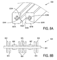
- Figure 8A shows a schematic perspective view of a possible embodiment of the chain guide 830.
- the chain guide comprises two profile pieces 831A, 831B with substantially rectangular cross-section, wherein a slot 833A, 833B is formed in one side face 832A, 832B, which slot 833A, 833B is provided with a transverse slot 834A, 834B.
- the two profile pieces 831A, 831B are arranged with the slots 833A, 833B facing each other. These slots 833A, 833B form a guide and a confinement for a push chain 820.
- Figure 8B shows a schematic cross-sectional view of a push chain 820 in the chain guide 830.
- Figure 8C shows a schematic side view of a push chain 820 and figure 8D shows a schematic top view of the push chain 820. Since the design of a chain is commonly known, the design of the push chain 820 will be discussed only briefly.
- the chain of this example is a double chain; alternatively also a single chain or a triple chain may be applied.
- the push chain 820 has a series of transverse axles 821. On each axle 821, two rolls 826, 827 are attached next to each other.
- the transverse axles 821 are coupled to each other by links 822, 823, 824, 825.
- Primary links 822 always couple an end of an axle 821(i) with an end of a next neighbouring axle 821(i+1).
- Secondary links 823 always couple an end of an axle 821(i) to an end of a preceding neighbouring axle 821(i-1).
- Primary central links 825 located between the rolls 826, 827 always couple the centre of the axle 821(i) to the centre of the next neighbouring axle 821(i+1).
- Secondary central links 824 located between the rolls 826, 827 always couple the centre of the axle 821(i) to the centre of the preceding neighbouring axle 821(i-1).
- the rolls 826, 827 roll along the walls of the guide slots 833A, 833B of the profile pieces 831A, 831B of the chain guide 830.
- the primary and secondary links 822, 823 slide in the transverse slots 834A, 834B of the profile pieces 831A, 831B.
- the primary and secondary central links 824, 825 are situated between the profile pieces 831A, 831B.
- Figure 8E is a schematic side view of a post 850 according to the invention, similar to figure 3.
- the figure schematically shows that, at its lower end, the post 850 is provided with a storage case 851 for the push chain 820, in which the push chain 820 can be stored in a rolled-up state, as will be explained more elaborately later.
- a drive motor 852 is arranged for driving the push chain 820.
- An advantage of this construction is that the heavy motor is situated near the foot of the post, and that a carriage 840 (object carrier) can remain relatively light.
- the motor 852 drives chain wheels, which chain wheels engage with the chain, as is known per se and not shown for the sake of simplicity.
- Figure 8E further shows that an object carrier or carriage 840 is coupled to the free end of the push chain 820.
- the carriage 840 In a rest position, the carriage 840 is situated at the lower end of the post 850, and the push chain 820 is situated inside the storage case 851.
- the motor When the motor is actuated, the push chain 820 is driven in order to displace linearly within the tubular guide 830, in which case the end of the push chain 820 pushes up the carriage 840.
- the motor 852 is shut down, the push chain 820 stands still and with that also the carriage 840.
- the carriage 840 When the motor 852 is actuated in opposite direction, the carriage 840 is moved down again.
- a chain can be bent in a direction perpendicular to the longitudinal direction of the transverse axles 822.
- An undesired bending of the push chain 820 is prevented because the push chain 820 is confined in the slot 833A, 833B and/or the transverse slots 834A, 834B.
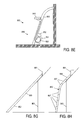
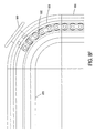
- An important advantage of the use of a bendable push chain is that the post 850 does not necessarily need to have a straight shape, but may be bent, as is also illustrated in figure 8E.
- Figure 8F is a schematic side view illustrating that the post 803 may contain substantial bends, which are easily followed by the push chain 820.
- Figure 8F shows a bend of 90°, but a bend may also extend through a larger angle. Then, it is possible that the post 850 contains a horizontal piece 855, so that the carriage 840 can be displaced horizontally by the motor 852 without an extra motor being needed for that.
- FIG. 8G shows the application of a straight post 860: since the post 860 must stand under a certain angle in order to be able to reach the roof window 861, the foot 862 of the post 860 must stand at a fairly large distance from the outer wall 863.
- Figure 8H shows that, in the case of a bent post 850, the foot of the post can stand less far from the outer wall. This is an advantage that is not only of importance when positioning awnings, but also with builder's hoists and the like.
- Figure 8J shows a schematic perspective view of a storage case 851 for the push chain 820
- figure 8K shows a schematic cross-section of the storage case 851.
- the storage case 851 has a slot 853 with a transverse slot 854, similar to the slot 833 and transverse slot 834 of the guide 830, wherein the guide slot 853 of the storage case 851 contains some bends and thus defines a spiral-shaped trajectory.
- the guide slot 853 of the storage case 851 fits to the guide slot 833 of the guide 830.
- the total length of the spiral-shaped guide slot 853 in the storage case 851 corresponds to the length of the push chain 820 to be used, which is situated entirely inside the storage case 851 in retracted state.
- the storage case 851 shown in figure 8J accomodates only one half of a push chain (seen along the longitudinal direction: the left half or the right half).
- the other half of the rolled-up push chain projects from this storage case 851 without trouble.
- this other half of the rolled-up push chain may be accomodated incide a storage case if a second storage case (mirror image of the storage case 851 shown) is placed next to the storage case 851 shown.
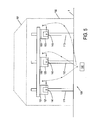
- Figure 5 schematically illustrates a preferred embodiment of a positioning system 100 according to the present invention intended for positioning long awnings and the like.
- Figure 5 is a schematic front view of a house 101 (sketched in a dotted way), with an outer wall 102 against which a long awning 103 is to be mounted.
- a positioning system 100 with three independent posts 111, 112, 113, which may each be equal to the post 31 described in the above.
- Each post 111, 112, 113 has an object carrier 121, 122, 123 associated with it, which may each be equal to the object carrier 40 described in the above.
- Each object carrier 121, 122, 123 has a platform 131, 132, 133, on which is awning 103 is lying.
- Each object carrier 121, 122, 123 is further provided with a motor 141, 142, 143.
- Each motor 141, 142, 143 has a variable speed, and is remotely controllable.
- An important aspect of the positioning system 100 is that it has a common control member 150, which can drive all motors 141, 142, 143 possibly by means of cables but preferably and as illustrated wireless. Thus, it is possible that one single person operates all three positioning lifts by means of operating the common control unit 150.
- the control unit 150 may be adapted to make all motors 141, 142, 143 run at the same speed in order to thus have all three object carriers 121, 122, 123 move upward at the same speed along the corresponding posts 111, 112, 113.
- the control member 150 is also adapted to control the motors 141, 142, 143 individually, for example in order to thus compensate for irregularities or slopes in the bottom 1 in order to thus attain and maintain a horizontal position of the awning 103.
- each motor may be provided with an own accumulator or battery. Because of the simplicity, such accumulator or battery is not shown separately in the figures.
- the coupling members 44 are preferably provided with a manual control, for example in the form of a crank mechanism.
- This manually controlled crank mechanism may thus function as emergency control, but, if desired, may also be used for a manually controlled fine-tuning of the position of the object carrier 40.
- An important aspect of a good positioning aid is the degree of accuracy with which that aid is able to position an object to be positioned. If the positioning is not exactly right, then, for mounting an awning, it is still needed to lift the awning manually to its final position.
- the positioning lift 30 according to the present invention already offers the advantage that a good positioning accuracy is attained. In practice however, it may happen that one desires to attain a very high positioning accuracy, and that this high positioning accuracy is difficult to attain by only operating the motor 45, even though it is possible to let that motor run at very low speed.
- the object carrier 40 has only one point of closest approach to the outer wall 2, namely the upper extreme position of the object carrier 40 relative to the carrier 31. That upper extreme position can be defined because the object carrier 40 touches the outer wall 2, or because the object carrier 40 has reached the extreme point of the displacement range along the post 31. From that extreme point onwards, a further displacement of the object carrier upward is not possible, while a displacement of the object carrier 40 downward along the carrier 31 always involves an increasing distance relative to the outer wall 2.
- a further improvement of the positioning system according to the present invention can then be attained if the platform 41 of the object carrier 40 is displaceable relative to the frame 42.
- That displacement possibility can be a vertical displacement possibility and/or a horizontal displacement possibility.
- a separate motor may be present (not shown for the sake of simplicity), which motor may be remotely operable.
- the positioning lift 30 has multiple segments from which the carrier 31 can be composed, wherein the different segments have different lengths in order thus to be able to choose the total length of the post 31 by choosing suitable post segments.
- the positioning lift 30 could have one lower segment 31A, one upper segment 31C, and multiple intermediate segments 31B of different lengths.
- the carrier 31 When it is desired to change the length of the carrier 31, the carrier 31 would then have to be disassembled and reassembled wherein the one intermediate segment 31B is replaced by another intermediate segment 31B.
- the lower segment 31A of the post 31 is adjustable in length.
- the lower end of the lower segment 31A is provided with a screw leg 36. By screwing the screw leg 36 in or out, the total length of the lower segment 31A can be changed.
- a screw leg 36 instead of a screw leg 36, other constructional solutions are conceivable for extending or reducing the length of the lower segment 31A, as will be clear to a person skilled in the art.
- the positioning lift 30 is provided with an accessory 60 which enables the usability of the positioning lift 30 also in situations where the positioning lift could not be placed on the right position relative to the outer wall 2 due to the presence of obstacles.
- an obstacle is indicated with the reference number 3.
- the accessory 60 comprises an extra post 61 which, for example, can be placed against the outer wall 2 and of which the length is adjustable, and a beam 62 which can be coupled with the post 61 at its one end and which can be coupled with the upper end 32 of the post 31 at its other end. During use, the beam 62 is directed substantially horizontally.
- the upper end 32 of the post 31 is then situated at a distance from the outer wall 2, which distance is defined by the length of the beam 62.
- the beam 62 may also be adjustable in length, or a set of multiple individual beams 62 having mutually different lengths may be provided for.
- the beam 62 is mounted to the upper end 32 of the beam 31 such that the upper surface of the beam 62 is situated substantially in the same horizontal plane as the upper surface of the platform 41 when the object carrier 40 is in its upper position. However, this is not necessary, since the vertical position of the object carrier 40 is adjustable by means of the motor 45, or because the vertical position of the platform 41 relative to the frame 42 is adjustable.
- an awning 103 is transported upward by the object carrier 40 until the platform 41 is substantially at the same height as the beam 62. Then, the awning 103 is slid off the platform 41 and slid over the beam 62 up to the outer wall 2.
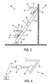
- Figure 7 shows a preferred embodiment which solves also that problem.
- the positioning lift 30 comprises a second post 71, which may be identical to the first post 31, except that no object carrier 40 needs to be transported along the second post 71. Therefore, the second post 71 may be implemented simpler than the first post 31. Nevertheless, it offers advantage to implement the second post 71 identical to the first post 31, because that second post 71 can then also fulfil the role of first post 31 in a situation that multiple posts are used at the same time, as illustrated in figure 5.
- the positioning lift has a beam 72 connected between the upper ends of the first post 31 and the second post 71.
- an awning to be installed is transported upward by the object carrier 40 until the platform 41 is substantially level with the upper surface of the beam 72, after which the awning is slid off the platform 41 and slid on the beam 72 for a horizontal positioning.
- this embodiment is particularly suitable for installing an awning or the like under the ceiling of a overhanging roof part.
- the posts 31 and 71 are adjustable in height, as indicated schematically with arrows.
- the lower ends of the posts 31 and 71 are preferably coupled with each other by means of a connecting bar, or the like, which coupling bar is not shown in figure 7 for the sake of simplicity.
- a post consists of one piece
- a post 850 is composed of multiple segments 857 (see figure 8H). That also has the advantage that the total length of a post can be varied by enlarging or reducing the number of segments in the post. Dangerous situations might arise if the segments are not coupled well with each other.
- a post has an end segment 858 which is provided with a mechanical lock for the carriage.
- the post end segment 858 may be provided with a block or closing of the guide slot;
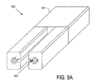
- figure 9A schematically shows in perspective view an example of an end segment 930 for the guide 830, provided with a stop 931 which blocks the guide slot 833 completely.
- Other embodiments of such a stop are also possible. The consequence of such a stop is then, that the push chain will not be able to be displaced further than a position wherein the free end of the push chain strikes against that block 931.
- the motor 852 is shut down automatically when the push chain reaches that block; it could otherwise be possible that the push chain presses the segments of the post apart due to the force present in the motor. Therefore, as extra security, the end segment 858 is preferably provided with a switch which is operated by the push chain or the carriage shortly before the push chain strikes against that block.
- FIG. 9B schematically shows a post segment 857, wherein constructional details of the post segment have been neglected.
- the figure shows that, at its upper end 911, each post segment 857 is provided with a first electrical connector 921 attached to it, and, at its lower end 912, is provided with a second electrical connector 922 attached to it, fitting to the first electrical connector 921.
- Each connector 921, 922 has at least two contacts.
- the first electrical connector 921 is a female connector and the second electrical connector 922 is a matching male connector.
- Each contact of the first electrical connector 921 is connected with a corresponding contact of the second electrical connector 922 through an electrical conductor 923.
- the positioning of those connectors 921, 922 is always such that the second electrical connector 922A of the subsequent post segment 857A is coupled automatically with the first electrical connector 921 of the preceding post segment 857.
- an extra security switch (not shown) is incorporated in the electrical conductor 923, which is normally open (i.e. not conducting), and which is operated mechanically by the subsequent post segment 857A in order to be closed when the subsequent post segment 857A is installed correctly. Even if the connectors 921, 922A would make good contact, the conductor 923 could then still not form a closed circuit when the subsequent post segment 857A does not fit correctly to the preceding post segment 857, because then this extra safety switch is open.
- a post end segment 858 has a second electrical connector 922 only at its lower end.
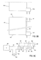
- the contacts of that second electrical connector are connected electrically with each other, for example by a direct connection, but preferably by an end switch 924 (see figure 9C) which is normally closed (i.e. conducting): only when the end switch 924 is operated by the approach of a carriage or the approach of a push chain, the end switch will open.
- the localisation of that end switch 924 is such that it opens yet before the end of the push chain reaches the stop of the post end segment 858.
- Figure 9C schematically shows an electric control circuit for a motor 852 of the positioning system 800.
- the motor 852 is supplied from a supply 950, through supply lines 951, 952, 953.
- the supply is a controllable supply in order to let the motor run at adjustable speed. Both the motor and the supply are arranged near the lower end of the post.
- At least one supply line 951, 953 goes through the said electrical connectors 921, 922 and the electrical conductors 923 of the post segments 857 (which in the figure are shown horizontally for the sake of simplicity) to the end switch 924 of the post end segment 858.
- a motor connector 925 is connected to the second connector 922 of the lower post segment 857.
- a first supply line 951 extends between a supply exit and a first contact of the motor connector 925.
- a second supply line 951 extends between a supply exit and a first connection of the motor 852.
- a third supply line 953 extends between a second connection of the motor 852 and a second contact of the motor connector 925. Alternatively, the first and third supply line 953 could be connected to the first connector 921 of the lower post segment 857.
- the push member is composed as push chain with discrete links.
- the push member might as well be implemented as a continuous push belt, or as a bendable rod. It is only important that the push member combines the quality of bendability with sufficient push strength.
Landscapes
- Engineering & Computer Science (AREA)
- Structural Engineering (AREA)
- Civil Engineering (AREA)
- Transportation (AREA)
- Automation & Control Theory (AREA)
- Power-Operated Mechanisms For Wings (AREA)
- Control Of Position Or Direction (AREA)
Abstract
Description
Claims (30)
- Positioning lift (30; 800), adapted as mounting aid, for example for mounting awnings, comprising:a post (31);an object carrier (40) which is displaceable along the post (31);displacement coupling means (44) for coupling the object carrier (40) with the post (31) and for performing a displacement of the object carrier relative to the post;a motor (45) for driving the displacement coupling means (44), which motor (45) can be controlled with variable speed; control means (50) for controlling the motor (45).
- Positioning lift according to claim 1, wherein the motor control means (50) are associated with the object carrier (40).
- Positioning lift according to claim 1 or 2, wherein the motor control means (50) are adapted to remotely control the motor (45).
- Positioning lift according to claim 3, wherein the motor control means (50) are adapted to wirelessly control the motor (45), for example by means of an infrared remote control or radio remote control.
- Positioning lift according to any of the preceding claims, wherein the object carrier (40) is provided with a carrying platform (41), and wherein the displacement coupling means (44) are located under that platform (41).
- Positioning lift according to any of the preceding claims, wherein the post (31) is composed of two or more post segments (31A, 31B, 31C).
- Positioning lift according to any of the preceding claims, wherein, at its upper end (32), the post (31) is provided with an oblique supporting plane (33) which, in the working position of the post (31), is substantially directed vertically.
- Positioning lift according to any of the preceding claims, wherein, at its lower end, the post (31) is provided with height adjustment means (36).
- Positioning lift according to claim 8, wherein the positioning means comprise a rotary leg (36).
- Positioning lift according to any of the preceding claims, wherein the object carrier (40) has a frame (42) and a platform (41) which is adjustable relative to the frame.
- Positioning lift according to claim 10, wherein the platform (41) is adjustable in vertical direction relative to the frame (42).
- Positioning lift according to claim 10 or 11, wherein the platform (41) is adjustable in horizontal direction relative to the frame (42).
- Positioning lift according to any of the claims 10 to 12, wherein the platform (41) is adjustable relative to the frame (42) by means of manual control.
- Positioning lift according to any of the claims 10 to 13, further provided with a platform adjustment motor for adjusting the platform (41) relative to the frame (42).
- Positioning lift according to claim 14, wherein the platform adjustment motor can be remotely controlled.
- Positioning lift according to any of the preceding claims, further comprising an auxiliary post (61; 71) and an auxiliary beam (62; 72), which auxiliary beam, at its one end, is attachable to the upper end (32) of the first post (31), and with its other end, is attachable to the upper end of the auxiliary post (61; 71).
- Positioning lift according to any of the preceding claims, wherein the displacement coupling means (44) comprise a worm associated with the object carrier (40) and a rack associated with the post (31).
- Positioning lift (800) according to any of the preceding claims, wherein the displacement coupling means (820) comprise a flexible push member (820) guided in a tubular guide (830); wherein the object carrier (840) is connected with the free end of the push member (820);
and wherein a drive motor (852) for driving the push member (820) is arranged at the lower end of the post (850). - Positioning lift according to claim 18, wherein the displacement coupling means (820) comprise a push chain.
- Positioning lift according to claim 18 or 19, wherein a storage case (851) is located at the lower end of the post (850) for incorporating the push member (820) in a state wound to a spiral shape.
- Positioning lift according to claim 20, wherein the storage case (851) comprises a guide slot (853) bent according to a spiral shape.
- Positioning lift according to any of the claims 18-21, wherein the post (850) has at least one curve.
- Positioning lift according to any of the claims 18-22, wherein a stop (931) for the push member (820) is located at the upper end of the post (850).
- Positioning lift according to claim 23, wherein an end switch (924) which is to be operated by the push member (820) or by the object carrier (840) is located at the upper end of the post (850), at such a position that the end switch (924) is operated before the free end of the push member (820) has reached the stop (931).
- Positioning lift according to any of the claims 1-5 or 18-24, wherein the post (31; 850) is composed of two or more post segments (31A, 31B, 31C; 857, 857A, 858);
wherein a first electrical connector (921) is attached to the upper end (911) of a post segment (857),
wherein a second electrical connector (922) which fits to the first electrical connector (921) is attached to the lower end (912) of a post segment (857),
wherein the first electrical connector (921) and the second electrical connector (922) are connected by an electrical conductor (923) extending along the post (857);
and wherein the motor (852) is supplied by an electric supply circuit in which said electrical conductors (923) of the post segments (857) are incorporated. - Positioning system (100), comprising a plurality of positioning lifts (30; 800) according to any of the preceding claims.
- Positioning system according to claim 26, provided with a common control member (150) for commonly controlling the individual motors (141; 142; 143) of the individual positioning lifts.
- Positioning system according to claim 27, wherein the common control member (150) is adapted to drive all motors of the different positioning lifts equally fast.
- Positioning system according to claim 27, wherein the control member (150) is adapted to drive the different motors of the different positioning lifts at mutually different speeds.
- Positioning system according to any of the claims 27-29, wherein the common control member (150) is adapted to wirelessly drive the different motors of the different positioning lifts, for example by means of infrared control or radio control.
Applications Claiming Priority (2)
| Application Number | Priority Date | Filing Date | Title |
|---|---|---|---|
| NL1025757 | 2004-03-18 | ||
| NL1025757A NL1025757C2 (en) | 2004-03-18 | 2004-03-18 | Positioning lift. |
Publications (2)
| Publication Number | Publication Date |
|---|---|
| EP1591402A2 true EP1591402A2 (en) | 2005-11-02 |
| EP1591402A3 EP1591402A3 (en) | 2008-11-05 |
Family
ID=34938107
Family Applications (1)
| Application Number | Title | Priority Date | Filing Date |
|---|---|---|---|
| EP05075663A Withdrawn EP1591402A3 (en) | 2004-03-18 | 2005-03-18 | Material positioning lift |
Country Status (2)
| Country | Link |
|---|---|
| EP (1) | EP1591402A3 (en) |
| NL (1) | NL1025757C2 (en) |
Cited By (5)
| Publication number | Priority date | Publication date | Assignee | Title |
|---|---|---|---|---|
| KR101036906B1 (en) | 2010-11-22 | 2011-05-25 | 주식회사 리프텍 | Tilt and Speed Control of Lift Cage and Method |
| US8336286B2 (en) | 2010-02-10 | 2012-12-25 | Prince Castle LLC | Push chain with a bias spring to prevent buckling |
| US8376193B2 (en) | 2010-01-08 | 2013-02-19 | Prince Castle, LLC | Rodless dispenser |
| US8381950B2 (en) | 2010-01-08 | 2013-02-26 | Prince Castle, LLC | Piston and piston rod for a rodless dispenser |
| KR101435376B1 (en) | 2013-08-30 | 2014-08-28 | 삼성중공업 주식회사 | Apparatus to install blade of wind generation |
Family Cites Families (5)
| Publication number | Priority date | Publication date | Assignee | Title |
|---|---|---|---|---|
| US4183423A (en) * | 1976-08-12 | 1980-01-15 | Lewis James P | Ladder hoist |
| US5125481A (en) * | 1990-09-26 | 1992-06-30 | Hideaki Shibata | Diagonal elevation apparatus |
| US5452774A (en) * | 1993-10-25 | 1995-09-26 | Davis; Link H. | Endless roller chain drive with interlocking traction rail |
| JPH082843A (en) * | 1994-06-17 | 1996-01-09 | Toyo Electric Mfg Co Ltd | Elevator speed controller with remote setting function |
| DE102004005762A1 (en) * | 2004-02-05 | 2005-09-01 | Rema Lipprandt Gmbh & Co. Kg | Control system pedestrian controlled vehicle especially for fork lift truck has at least one control wheel with proportional control linked to selected operating actions |
-
2004
- 2004-03-18 NL NL1025757A patent/NL1025757C2/en not_active IP Right Cessation
-
2005
- 2005-03-18 EP EP05075663A patent/EP1591402A3/en not_active Withdrawn
Cited By (5)
| Publication number | Priority date | Publication date | Assignee | Title |
|---|---|---|---|---|
| US8376193B2 (en) | 2010-01-08 | 2013-02-19 | Prince Castle, LLC | Rodless dispenser |
| US8381950B2 (en) | 2010-01-08 | 2013-02-26 | Prince Castle, LLC | Piston and piston rod for a rodless dispenser |
| US8336286B2 (en) | 2010-02-10 | 2012-12-25 | Prince Castle LLC | Push chain with a bias spring to prevent buckling |
| KR101036906B1 (en) | 2010-11-22 | 2011-05-25 | 주식회사 리프텍 | Tilt and Speed Control of Lift Cage and Method |
| KR101435376B1 (en) | 2013-08-30 | 2014-08-28 | 삼성중공업 주식회사 | Apparatus to install blade of wind generation |
Also Published As
| Publication number | Publication date |
|---|---|
| EP1591402A3 (en) | 2008-11-05 |
| NL1025757C2 (en) | 2005-09-20 |
Similar Documents
| Publication | Publication Date | Title |
|---|---|---|
| US6550081B2 (en) | Lift bed with belt drive | |
| ES2271353T3 (en) | ACTUATING SYSTEM AND OPENING ELEMENT THAT INCLUDES SUCH SYSTEM. | |
| US7040374B2 (en) | Electromagnetic clutch-controlled electric blind | |
| KR101580528B1 (en) | Trolley For Structure Assembly | |
| KR100965742B1 (en) | Portable light bridge with acoustic reflector | |
| EP1591402A2 (en) | Material positioning lift | |
| KR101690273B1 (en) | Lifting apparatus for height work | |
| US9957720B1 (en) | Retractable staircase and method | |
| CN113013612B (en) | An angle-adjustable windproof 5G antenna device | |
| US20100166411A1 (en) | Mast assembly | |
| US3801813A (en) | Combination mast and light raising and lowering apparatus | |
| KR101957836B1 (en) | Portable charging module for electric vehicles | |
| JPH1087263A (en) | Article hoisting accessory | |
| EP1309762B1 (en) | Building comprising a device for moving a plattform along a facade | |
| JP6113434B2 (en) | Daylighting equipment | |
| JP2001115761A (en) | Falling restricting sensor construction for sheet shutter | |
| JP2014029089A (en) | Motor-driven solar radiation control apparatus and method of lifting/lowering lifting body of motor-driven solar radiation control apparatus | |
| KR20180012881A (en) | Structure of veranda installed with room for outside unit of air-conditioner within house | |
| CN114284945B (en) | Cable supporting device | |
| JP2987712B2 (en) | Movable ceiling storage | |
| JP2017186807A (en) | Electric roll screen device and tilt detection sensor | |
| CN216282412U (en) | Efficient automatic drying equipment for building board | |
| CN120817521A (en) | Hoisting device for operating room, control method thereof, and hoisting system | |
| CN221917003U (en) | Hoisting device and hoisting system for operating room | |
| CN118062774A (en) | Clamping type electrical cabinet installation device integrating carrying and positioning and use method thereof |
Legal Events
| Date | Code | Title | Description |
|---|---|---|---|
| PUAI | Public reference made under article 153(3) epc to a published international application that has entered the european phase |
Free format text: ORIGINAL CODE: 0009012 |
|
| AK | Designated contracting states |
Kind code of ref document: A2 Designated state(s): AT BE BG CH CY CZ DE DK EE ES FI FR GB GR HU IE IS IT LI LT LU MC NL PL PT RO SE SI SK TR |
|
| AX | Request for extension of the european patent |
Extension state: AL BA HR LV MK YU |
|
| PUAL | Search report despatched |
Free format text: ORIGINAL CODE: 0009013 |
|
| AK | Designated contracting states |
Kind code of ref document: A3 Designated state(s): AT BE BG CH CY CZ DE DK EE ES FI FR GB GR HU IE IS IT LI LT LU MC NL PL PT RO SE SI SK TR |
|
| AX | Request for extension of the european patent |
Extension state: AL BA HR LV MK YU |
|
| AKX | Designation fees paid | ||
| REG | Reference to a national code |
Ref country code: DE Ref legal event code: 8566 |
|
| STAA | Information on the status of an ep patent application or granted ep patent |
Free format text: STATUS: THE APPLICATION IS DEEMED TO BE WITHDRAWN |
|
| 18D | Application deemed to be withdrawn |
Effective date: 20090506 |