EP1591702A1 - Gehäuseanordnung - Google Patents
Gehäuseanordnung Download PDFInfo
- Publication number
- EP1591702A1 EP1591702A1 EP20050252700 EP05252700A EP1591702A1 EP 1591702 A1 EP1591702 A1 EP 1591702A1 EP 20050252700 EP20050252700 EP 20050252700 EP 05252700 A EP05252700 A EP 05252700A EP 1591702 A1 EP1591702 A1 EP 1591702A1
- Authority
- EP
- European Patent Office
- Prior art keywords
- housing
- shaft
- conduit
- flapper
- plate
- Prior art date
- Legal status (The legal status is an assumption and is not a legal conclusion. Google has not performed a legal analysis and makes no representation as to the accuracy of the status listed.)
- Granted
Links
- 238000000034 method Methods 0.000 claims description 12
- 239000004697 Polyetherimide Substances 0.000 claims description 4
- 238000005520 cutting process Methods 0.000 claims description 4
- 229920001601 polyetherimide Polymers 0.000 claims description 4
- OKTJSMMVPCPJKN-UHFFFAOYSA-N Carbon Chemical compound [C] OKTJSMMVPCPJKN-UHFFFAOYSA-N 0.000 claims description 3
- 229910052799 carbon Inorganic materials 0.000 claims description 3
- 229920005989 resin Polymers 0.000 claims description 3
- 239000011347 resin Substances 0.000 claims description 3
- 230000009977 dual effect Effects 0.000 abstract description 2
- 239000012530 fluid Substances 0.000 abstract description 2
- 230000000712 assembly Effects 0.000 abstract 1
- 238000000429 assembly Methods 0.000 abstract 1
- 239000000463 material Substances 0.000 description 14
- 229920004738 ULTEM® Polymers 0.000 description 4
- XAGFODPZIPBFFR-UHFFFAOYSA-N aluminium Chemical compound [Al] XAGFODPZIPBFFR-UHFFFAOYSA-N 0.000 description 4
- 229910052782 aluminium Inorganic materials 0.000 description 4
- 238000007789 sealing Methods 0.000 description 4
- 230000007613 environmental effect Effects 0.000 description 3
- 230000006835 compression Effects 0.000 description 2
- 238000007906 compression Methods 0.000 description 2
- 230000013011 mating Effects 0.000 description 2
- 238000000926 separation method Methods 0.000 description 2
- 229910000838 Al alloy Inorganic materials 0.000 description 1
- 229920000049 Carbon (fiber) Polymers 0.000 description 1
- 238000004026 adhesive bonding Methods 0.000 description 1
- 229910045601 alloy Inorganic materials 0.000 description 1
- 239000000956 alloy Substances 0.000 description 1
- 229920006127 amorphous resin Polymers 0.000 description 1
- 239000004917 carbon fiber Substances 0.000 description 1
- 230000000694 effects Effects 0.000 description 1
- 239000011152 fibreglass Substances 0.000 description 1
- 239000000945 filler Substances 0.000 description 1
- 238000009434 installation Methods 0.000 description 1
- 230000002452 interceptive effect Effects 0.000 description 1
- 229910001095 light aluminium alloy Inorganic materials 0.000 description 1
- 239000000314 lubricant Substances 0.000 description 1
- 238000012423 maintenance Methods 0.000 description 1
- VNWKTOKETHGBQD-UHFFFAOYSA-N methane Chemical compound C VNWKTOKETHGBQD-UHFFFAOYSA-N 0.000 description 1
- 238000012986 modification Methods 0.000 description 1
- 230000004048 modification Effects 0.000 description 1
- 229920003023 plastic Polymers 0.000 description 1
- 239000004033 plastic Substances 0.000 description 1
- 238000003825 pressing Methods 0.000 description 1
- 239000000126 substance Substances 0.000 description 1
- 229920001169 thermoplastic Polymers 0.000 description 1
- 239000004416 thermosoftening plastic Substances 0.000 description 1
- 238000003466 welding Methods 0.000 description 1
Images


Classifications
-
- F—MECHANICAL ENGINEERING; LIGHTING; HEATING; WEAPONS; BLASTING
- F16—ENGINEERING ELEMENTS AND UNITS; GENERAL MEASURES FOR PRODUCING AND MAINTAINING EFFECTIVE FUNCTIONING OF MACHINES OR INSTALLATIONS; THERMAL INSULATION IN GENERAL
- F16K—VALVES; TAPS; COCKS; ACTUATING-FLOATS; DEVICES FOR VENTING OR AERATING
- F16K1/00—Lift valves or globe valves, i.e. cut-off apparatus with closure members having at least a component of their opening and closing motion perpendicular to the closing faces
- F16K1/16—Lift valves or globe valves, i.e. cut-off apparatus with closure members having at least a component of their opening and closing motion perpendicular to the closing faces with pivoted closure-members
- F16K1/18—Lift valves or globe valves, i.e. cut-off apparatus with closure members having at least a component of their opening and closing motion perpendicular to the closing faces with pivoted closure-members with pivoted discs or flaps
- F16K1/22—Lift valves or globe valves, i.e. cut-off apparatus with closure members having at least a component of their opening and closing motion perpendicular to the closing faces with pivoted closure-members with pivoted discs or flaps with axis of rotation crossing the valve member, e.g. butterfly valves
- F16K1/224—Details of bearings for the axis of rotation
- F16K1/225—Details of bearings for the axis of rotation the axis of rotation having only one bearing
-
- F—MECHANICAL ENGINEERING; LIGHTING; HEATING; WEAPONS; BLASTING
- F16—ENGINEERING ELEMENTS AND UNITS; GENERAL MEASURES FOR PRODUCING AND MAINTAINING EFFECTIVE FUNCTIONING OF MACHINES OR INSTALLATIONS; THERMAL INSULATION IN GENERAL
- F16K—VALVES; TAPS; COCKS; ACTUATING-FLOATS; DEVICES FOR VENTING OR AERATING
- F16K27/00—Construction of housing; Use of materials therefor
- F16K27/02—Construction of housing; Use of materials therefor of lift valves
- F16K27/0209—Check valves or pivoted valves
- F16K27/0218—Butterfly valves
-
- Y—GENERAL TAGGING OF NEW TECHNOLOGICAL DEVELOPMENTS; GENERAL TAGGING OF CROSS-SECTIONAL TECHNOLOGIES SPANNING OVER SEVERAL SECTIONS OF THE IPC; TECHNICAL SUBJECTS COVERED BY FORMER USPC CROSS-REFERENCE ART COLLECTIONS [XRACs] AND DIGESTS
- Y10—TECHNICAL SUBJECTS COVERED BY FORMER USPC
- Y10T—TECHNICAL SUBJECTS COVERED BY FORMER US CLASSIFICATION
- Y10T137/00—Fluid handling
- Y10T137/8593—Systems
- Y10T137/877—With flow control means for branched passages
- Y10T137/87788—With valve or movable deflector at junction
- Y10T137/8782—Rotary valve or deflector
Definitions
- the present invention relates to mounting housings for use with valves. More particularly the invention relates to methods and materials for constructing and installing a diverter valve in a multi-chambered conduit. The invention particularly relates to a mounting housing and assembly that can be used with a lounge valve for use in an environmental control conduit in aircraft.
- Aircraft and other vehicles often include climate control and environmental control systems.
- One aspect of such systems is the ability to divert or control air flow between two or more positions.
- a lounge valve system which controls air flow.
- a series of valves directs air between the pilot's position and the co-pilot's position.
- air from some environmental control unit such as an air conditioner or heater is directed to a general location, such as the cockpit of an airplane, through a single duct.
- the single duct then splits into two (or more) branches in order to direct air to specific locations.
- a typical arrangement involves a Y junction in which air from the source is then directed to the pilot's location and to the co-pilot's location by separate ducts.
- a flow valve Within each separate duct there is positioned a flow valve.
- this valve is an in-line valve such that the valve is inserted into the duct by cutting the duct, placing the valve at the cut location, and then clamping each of the two severed ends of the duct to the valve.
- Each valve is thus independently operated so as to close air flow or allow air flow from a partial to a full amount.
- a second disadvantage and limitation of the prior art method is the cost associated with multliple valve control.
- the capital cost of a single valve is duplicated with each additional valve installed on the system. Cost savings is always a desired improvement.
- a further disadvantage of the prior art lounge valve system is the difficulty of installing and servicing such a system.
- a system that uses in-line flow control valves requires a technician's labor to cut lines, install, remove and/or replace valves, and then reconnect the lines. This labor must be repeated for multiple valves if, as is typical, the system uses multiple in-line valves. A simpler system that reduces the need for such labor would be desired. Further, in the airplane environment, space is also at a premium. Thus any system that is more easily removed and/or replaced is also advantageous.
- the present invention provides a lounge valve mounting housing that is capable of mating or attaching to a valve or actuator arm such as a control valve.
- the mounting housing further includes a plate whereby the housing may be affixed to a conduit or duct.
- the housing also includes an assembly of a shaft and flapper whereby air flow within a duct may be controlled by movement of the flapper.
- a mounting housing assembly for connecting a valve actuator to a conduit comprising: a housing comprising a plate and a platform; a cylinder disposed on the housing; a shaft disposed within the cylinder; and a flapper attached to the shaft. Supports that separate the platform and the plate may also be included in the housing. In one embodiment the flapper does not contact the walls of the conduit. The flapper does provide a degree of air diversion or obstruction, such as the area obstructed is 70% of the passage area, and thus 30% of the passage area allows air to pass therethrough. An aluminum guide for the flapper may be disposed within the cylinder.
- a spring may be disposed within the shaft such that the spring biases the actuator arm and the shaft away from each other when the shaft receives the actuator arm.
- the shaft may further comprise a shoulder to limit the lateral motion of the shaft within the cylinder.
- the engagement means may comprise a toothed spline disposed within a hollow area of the shaft that is capable of receiving a reciprocal toothed spline of the actuator arm.
- the engagement means allow rotational movement of an actuator arm to impart rotational force onto the shaft and thereby onto the flapper.
- the housing may be a unitary piece comprised of carbon reinforced polyetherimide resin.
- the flapper may be aluminum.
- the shaft may be of the same material as the housing or different.
- the flapper may be of different shapes such as circular or parabolic.
- a method for affixing a diverter valve to a conduit comprising the steps of: cutting a slit in the conduit capable of passing a diverter valve flapper into the conduit; inserting a flapper and shaft through the slit into the interior of the conduit; and securing a housing plate to the conduit surface.
- the step of securing the housing plate to the footing may comprise bolting the housing plate to the footing.
- An additional step of placing a gasket between the housing plate and the footing may be included.
- the method may further comprising the step of preparing a footing on the conduit surface; and wherein the housing plate is secured to the footing. When a footing is not used a cushioned gasket may be placed on the surface of the conduit; and the housing plate secured to the conduit surface with the gasket between the housing plate and the conduit surface.
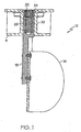
- FIG. 1 is a side view of a lounge valve mounting housing and assembly according to one embodiment of the invention.
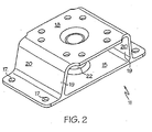
- FIG. 2 is a perspective view of a mounting housing according to one embodiment of the invention.
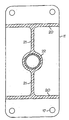
- FIG. 3 is a cross-sectional view of a mounting housing according to one embodiment of the invention.
- FIG. 4 is a perspective view of a lounge valve mounting housing and assembly, according to an embodiment of the invention, affixed to an exemplary actuator.
- FIG. 5 is a cross-sectional view of a mounting housing according to one embodiment of the invention.
- FIG. 1 An embodiment of the lounge valve mounting housing according to the present invention.
- the mounting housing 10 includes housing 11, shaft 13, and flapper 14.
- mounting housing 11 is a unitary molded piece with individual features.
- housing 11 may be assembled from components.
- housing 11 may be welded of individual aluminum pieces.
- Housing 11 includes plate 15.
- Plate 15 is a substantially planar surface.
- Plate 15 defines orifice 16.
- plate 15 is generally rectangular in shape although other shapes may be used.
- Bolt holes 17 may be drilled in plate 15.
- Plate 15 may be used to secure housing 11 such as to a duct or conduit.
- Mounting housing 11 also includes platform 18.
- Platform 18 is a surface onto which a further body such as an actuator assembly or control valve may be affixed. Thus the surface of platform 18 may be adapted to receive the corresponding mounting surface of the assembly or control valve.
- platform 18 is a substantially planar surface. Platform 18 may also have holes with which to affix a control valve to platform 18.
- bolts connect a control valve to platform 18. The bolts may be accessed through the open area that is defined between plate 15 and platform 18.
- FIG. 4 illustrates the appearance of mounting housing 10 with an actuator positioned on it.
- Supports 19 are preferably wall-like structures. Supports 19 provide a desired degree of separation between platform 18 and plate 15. The separation between platform 18 and plate 15 allows access to platform 18 and plate 15 in the area that lies between these two surfaces. This area is useful for accessing fasteners, such as bolts, that may be attached to housing 11 at platform 18 or plate 15.
- supports 19 include outer supports 20 and cylinder supports 21. This is illustrated in FIG. 3 which shows a cross section of housing 11. Cylinder supports 21 are set at a transverse position between outer supports 20 and cylinder 22. Transverse supports 21 provide stability and support to cylinder 22. In another embodiment transverse supports 21 are omitted from housing 11. When only outer supports 20 are used, when transverse supports 21 are not present, an optional weight savings can be achieved. Further weight saving can be achieved by cutting windows (removing material) from outer supports 20 as shown in FIG. 4.
- Cylinder 22 is a vertical structure running between platform 18 and plate 15. Cylinder 22 also provides a connection and support between platform 18 and plate 15. Cylinder 22 has a hollow interior so as to allow a shaft or rod to pass therethrough and rotate therein.
- the exterior shape of cylinder 22 can take various shapes, a cylindrical shape is preferred for weight and material savings. At the points where cylinder 22 meets platform 18 and plate 15, there is defined a hole that allows access to the hollow interior of cylinder.
- a bushing 23 may be disposed within cylinder 22.
- bushing 23 is preferably press fit within cylinder 22.
- cylinder 22 may include a shoulder that acts to retain bushing 23 at a desired position within cylinder 22.
- bushing 23 is not used in order to achieve weight and material savings.
- shaft 13 and cylinder 22 are selected of materials that have an acceptably low degree of friction so that no further bushing or lubricant is necessary.
- shaft 13 is configured to fit within the space defined by the interior of cylinder 22.
- Shaft 13 is thus generally cylindrical in shape at those points on shaft that are in contact with cylinder 22.
- Shaft 13 and cylinder 22 are sized so that shaft 13 is free to rotate within cylinder 22.
- shaft 13 includes a shoulder 24.
- Shoulder 24 acts to hold shaft 13 from moving axially within cylinder 22 beyond the point at which shoulder 24 contacts cylinder 22.
- housing 11 When shaft 13 is configured with shoulder 24, it is preferred to fabricate housing 11 with a flat landing area where shoulder 24 contacts housing 11. As shown in FIG. 1 this contact area generally corresponds to the area on platform 18 around the hole defined by cylinder 22.
- shaft 13 includes engagement means 25.
- engagement means 25 is preferably a hollow area located at the upper end of shaft 13, the end of shaft 13 that is generally located proximate to platform 18.
- engagement means 25 is configured at the end of shaft 13 with shoulder 24.
- engagement means 25 comprises a toothed spline that is capable of receiving a reciprocal toothed spline therein.
- Engagement means 25 may also comprise a gear.
- an actuator shaft (not shown) driven by a control valve may have a toothed spline that fits within engagement means 25 of shaft 13. In this manner, a control valve may impart a controlling motion on shaft 13.
- shaft 13 includes a spring 26 disposed within a hollow area of shaft 13.
- the hollow area wherein spring 26 is located is a continuation of the same hollow area that includes the spline.
- Spring 26 rests against a bottom portion of the hollow area; this bottom portion is a part of the body material of shaft 13.
- Spring 26, acting in conjunction with other components, acts to hold shaft 13 so that shoulder 24 is pressed against housing 11.
- an actuator will protrude into the area that comprises engagement means 25. In doing so, this actuator will depress spring 26. Spring, pressing against the actuator and shaft 13, will thus exert a force so as to bring shoulder 24 into contact with housing 11.
- flapper 14 is affixed to shaft 13. Different means of attachment may be used including welding, riveting, and bolting flapper 14 to shaft 13.
- shaft 13 is machined to be flat at the area where flapper 14 is attached. Flapper 14 can then be riveted or spot welded to shaft 13.
- flapper 14 is fabricated from a lightweight rigid material such as aluminum or aluminum alloy sheet.
- Flapper 14 is configured in profile so as to fit and move within a duct. As illustrated in FIG. 1, the flapper may take a parabolic shape in order to fit within a parabolic shaped duct. Other shapes are possible. Flapper 14 may be rounded or circular in shape for example. A circular shaped flapper disposed within a circular duct may act as a butterfly valve, allowing air passage and restricting air passage depending on the position of flapper 14 within the duct. In a preferred embodiment the outer edge of flapper 14 is cut so that it does not make contact with the interior surface of the duct within which it is positioned.
- the housing and components can be fabricated from any of the known engineering materials. Plastic materials are one acceptable material. In airplane environments, aircraft aluminum and alloys thereof are also acceptable. A preferred material with which to fabricate the housing and components is polyetherimide (PEI) thermoplastic developed and sold under the trade name ULTEM ®.
- PEI polyetherimide
- ULTEM ® was introduced by General Electric in the 1970's. It is an amorphous resin. It demonstrates high mechanical strength and rigidity, good chemical resistance, and inherently low flammability.
- ULTEM ® resin is machinable and has a stable dielectric constant. It is a material known and used to fabricate various aircraft components.
- ULTEM ® resin may be used as an unfilled resin; however, it is preferably used with a filler such as carbon or fiberglass.
- a preferred filling specification for the lounge valve mounting housing is approximately 20% carbon fiber reinforced.
- the lounge valve mounting housing is mounted onto a footing prepared on the duct that is to receive the housing.
- the footing is substantially flat and provides a mating surface on which the plate 15 of housing 11 may be affixed.
- a gasket may be interposed between the footing of the duct and plate 15 in order to minimize leakage of air or other fluid from the duct.
- the attachment of the mounting housing to the duct is preferably done in a slightly different fashion.
- a cushioned gasket is interposed between the housing and the duct.
- the cushioned gasket is a sponge-like structure of sufficient thickness so that when the housing is affixed to the duct, the housing compresses the gasket. The compression of the gasket acts to mold or adapt the gasket against the duct thereby providing a desired degree of sealing between the duct and the housing.
- the compression of the gasket also acts to provide a sealing surface against the housing.
- the cushioned gasket is selected so as to provide a desired degree of sealing between the mounting housing and the duct. Thicker cushion gaskets that are compressed provide a higher level of sealing than do thinner cushion gaskets.
- the lounge valve mounting housing of the present invention may be installed and put into service without the need of severing an existing duct.
- a slit is cut into the duct in the area of the footing.
- the geometry and dimension of the slit is sufficient to allow flapper 14 and shaft 13 to pass through the slit from the duct exterior into the interior area of the duct. Further the slit is of a sufficient size so as not to interfere with the operation of flapper 14 and shaft 13 when mounted.
- the mounting housing may be affixed to the duct once the flapper and shaft have been placed through the slit.
- the mounting housing may be affixed by any known method such as but not limited to bolting, screwing, gluing, clamping, and riveting.
- corresponding bolt holes are fashioned in the duct footing and in the mounting housing. The mounting housing is thus bolted to the duct once the bolt holes on the footing and the housing are aligned. As indicated in FIG. 3 the bolt holes are preferably positioned at four corners of housing. This position allows the mounting housing to be affixed to a duct without interfering with the flapper's operation in the duct.
- control valve When the mounting housing is affixed to the duct, the control valve may be attached to the mounting housing. Control lines such as power lines and signal lines may then be attached to the control valve.
- removal of the mounting housing generally involves the reversal of the above-noted steps. Control and power lines are disconnected from the control valve if desired. If desired, the control valve can be removed from the mounting housing.
- the mounting housing itsetf is removed from the duct by undoing whatever attachment means was used to attach the mounting housing. In the case of bolts, the bolts are removed. In removing the mounting housing, care should be taken to pass the flapper and shaft through the slit without damage thereto- At this point the control valve and mounting housing may be removed from the vehicle and serviced.
- the lounge valve mounting housing and assembly is affixed to a conduit or duct.
- a valve or actuator arm is also affixed to the housing.
- An actuator arm is connected to the shaft so that rotational movement of the actuator arm imparts a rotational movement onto the shaft, and therefore onto the flapper.
- movement of the actuator arm effects a movement of the flapper.
- the flapper is cut so as to obstruct a portion of the area of the conduit in a fully extended position.
- the area obstructed is preferably less than 100% of the cross-sectional area of the conduit.
- a flapper at most obstructs between about 60% to about 95% of the area of the conduit, and more preferably between about 60% and about 80% of the area of the conduit.
- a first advantage of the lounge valve mounting housing is the weight savings that is realized over prior art methods.
- a valve is disposed within each arm of a y-shaped conduit so as to independently control air flow through each branch of the conduit.
- Each valve includes a valve housing and structure.
- a single diverter is used thus achieving a significant weight savings.
- a further advantage associated with the lounge valve mounting housing is the improved cost and efficiency associated with its installation and service.
- the lounge valve is attached to the outside of a conduit and the flapper is inserted to the interior of the conduit through a slit.
- the flapper is inserted to the interior of the conduit through a slit.
Landscapes
- Engineering & Computer Science (AREA)
- General Engineering & Computer Science (AREA)
- Mechanical Engineering (AREA)
- Lift Valve (AREA)
- Valve Housings (AREA)
- Dry Shavers And Clippers (AREA)
- Motor Or Generator Frames (AREA)
- Fluid-Driven Valves (AREA)
Applications Claiming Priority (2)
| Application Number | Priority Date | Filing Date | Title |
|---|---|---|---|
| US836985 | 1992-02-14 | ||
| US10/836,985 US7093618B2 (en) | 2004-04-30 | 2004-04-30 | Lounge valve mounting housing and assembly |
Publications (2)
| Publication Number | Publication Date |
|---|---|
| EP1591702A1 true EP1591702A1 (de) | 2005-11-02 |
| EP1591702B1 EP1591702B1 (de) | 2007-07-18 |
Family
ID=34941117
Family Applications (1)
| Application Number | Title | Priority Date | Filing Date |
|---|---|---|---|
| EP20050252700 Expired - Lifetime EP1591702B1 (de) | 2004-04-30 | 2005-04-29 | Gehäuseanordnung |
Country Status (4)
| Country | Link |
|---|---|
| US (1) | US7093618B2 (de) |
| EP (1) | EP1591702B1 (de) |
| AT (1) | ATE367550T1 (de) |
| DE (1) | DE602005001650T2 (de) |
Cited By (2)
| Publication number | Priority date | Publication date | Assignee | Title |
|---|---|---|---|---|
| US7093618B2 (en) | 2004-04-30 | 2006-08-22 | Honeywell International, Inc. | Lounge valve mounting housing and assembly |
| EP1724503A3 (de) * | 2005-05-16 | 2007-03-14 | Honeywell International Inc. | Zusammenklappbare Welle und Steuerbaugruppe |
Families Citing this family (8)
| Publication number | Priority date | Publication date | Assignee | Title |
|---|---|---|---|---|
| US20090000119A1 (en) * | 2007-06-26 | 2009-01-01 | Honeywell International, Inc. | Valve assemblies having valve flowbodies and methods of manufacturing |
| US8070130B2 (en) | 2008-01-22 | 2011-12-06 | Fisher Controls International, Llc | Apparatus to bias valve closure members |
| JP4876112B2 (ja) * | 2008-09-30 | 2012-02-15 | 株式会社日立製作所 | すべり軸受装置 |
| US10302207B2 (en) | 2012-06-14 | 2019-05-28 | Honeywell International Inc. | Spring loaded HVAC damper |
| US10119721B2 (en) * | 2012-06-14 | 2018-11-06 | Honeywell International Inc. | Standoff for use with an insulated HVAC duct |
| DE102012108379A1 (de) | 2012-09-07 | 2014-03-13 | Johnson Electric Dresden Gmbh | Aktor für eine Ventileinheit zum Regeln eines Fluidflusses |
| US9732980B2 (en) | 2013-12-18 | 2017-08-15 | Honeywell International Inc. | HVAC actuator with range adjustment |
| US10941960B2 (en) | 2013-12-18 | 2021-03-09 | Ademco Inc. | HVAC actuator with position indicator |
Citations (5)
| Publication number | Priority date | Publication date | Assignee | Title |
|---|---|---|---|---|
| US4332271A (en) * | 1979-08-08 | 1982-06-01 | Eduard Rohr Ag | Throttling device for pipe conduits |
| US5458148A (en) * | 1993-06-24 | 1995-10-17 | Zelczer; Alex | Fluid flow control damper assembly and method |
| US5758684A (en) * | 1995-02-15 | 1998-06-02 | Johnson Service Company | Return-to-normal modular actuator |
| EP0972975A1 (de) * | 1998-02-10 | 2000-01-19 | Nkk Corporation | Durchflussregelventil für hochtemperatur und hochdruckbereich und verfahren um das verklemmen des ventilschaftes zu verhindern |
| NL1015552C2 (nl) * | 2000-06-28 | 2002-01-02 | El O Matic Bv | Aandrijfinrichting voor een klep. |
Family Cites Families (23)
| Publication number | Priority date | Publication date | Assignee | Title |
|---|---|---|---|---|
| US2676604A (en) * | 1950-04-07 | 1954-04-27 | Senna Edward | Combined control valve and bleeder valve |
| US3269785A (en) * | 1962-10-29 | 1966-08-30 | Universal American Corp | Flanged bearing |
| US4148458A (en) * | 1977-06-13 | 1979-04-10 | Fisher Controls Company | Tight shutoff butterfly valve |
| US4200258A (en) * | 1977-10-07 | 1980-04-29 | Ranco Incorporated | Butterfly valve |
| US4146458A (en) * | 1977-12-02 | 1979-03-27 | Exxon Research & Engineering Co. | Electrochemical device having an oxygen electrode containing a pyrochlore type compound electrocatalyst |
| US5169121A (en) * | 1990-12-24 | 1992-12-08 | Mitsubishi Electronics America, Inc. | Damper control mechanism |
| EP0513905B1 (de) * | 1991-05-16 | 1996-03-13 | Koninklijke Philips Electronics N.V. | Halbleiteranordnung und Verfahren zum Herstellen einer derartigen Anordnung |
| US5269493A (en) | 1993-01-27 | 1993-12-14 | Triten Corporation | Butterfly valve |
| US5533929A (en) * | 1993-12-29 | 1996-07-09 | Attridge, Jr.; Russell G. | Remotely trippable and resettable damper |
| JP2912284B2 (ja) * | 1997-01-30 | 1999-06-28 | 日本電気アイシーマイコンシステム株式会社 | レイアウトエディタおよびそのテキスト発生方法 |
| US6395187B1 (en) * | 1998-10-01 | 2002-05-28 | Noe Martinez Alanis | Horizontal solids recycler |
| US6394088B1 (en) * | 1998-11-06 | 2002-05-28 | Mark R. Frye | Oxygen-delivery system with portable oxygen meter |
| US6308723B1 (en) * | 1998-11-18 | 2001-10-30 | Alliedsignal, Inc. | Piezo-resistive position indicator |
| US6206034B1 (en) * | 1999-08-19 | 2001-03-27 | Agf Manufacturing, Inc. | Valve with integral flow switch |
| EP1083316B1 (de) * | 1999-09-08 | 2002-11-20 | Siemens VDO Automotive Inc. | Zusammenbau von Drosselklappen und Drosselklappenwelle |
| DE60025981T2 (de) * | 1999-11-01 | 2006-09-07 | Denso Corp., Kariya | Einlassluftsteuerungsventil für Brennkraftmaschine und Verfahren zu seiner Herstellung |
| US6508455B2 (en) * | 2000-12-28 | 2003-01-21 | Visteon Global Technologies, Inc. | Electronic throttle body gear train module |
| US6568417B2 (en) * | 2001-04-17 | 2003-05-27 | Intel Corporation | Throttle valve assembly |
| US6676109B2 (en) * | 2001-05-22 | 2004-01-13 | Kitz Corporation | Rotary valve |
| US6565087B1 (en) * | 2001-07-28 | 2003-05-20 | Taylor Earle R | Gift opening game |
| JP2003083093A (ja) * | 2001-09-11 | 2003-03-19 | Keihin Corp | 内燃機関における絞り弁制御装置 |
| US6588417B2 (en) * | 2001-10-25 | 2003-07-08 | General Electric Company | Reversible burner grate |
| US7093618B2 (en) | 2004-04-30 | 2006-08-22 | Honeywell International, Inc. | Lounge valve mounting housing and assembly |
-
2004
- 2004-04-30 US US10/836,985 patent/US7093618B2/en not_active Expired - Fee Related
-
2005
- 2005-04-29 AT AT05252700T patent/ATE367550T1/de not_active IP Right Cessation
- 2005-04-29 DE DE200560001650 patent/DE602005001650T2/de not_active Expired - Lifetime
- 2005-04-29 EP EP20050252700 patent/EP1591702B1/de not_active Expired - Lifetime
Patent Citations (5)
| Publication number | Priority date | Publication date | Assignee | Title |
|---|---|---|---|---|
| US4332271A (en) * | 1979-08-08 | 1982-06-01 | Eduard Rohr Ag | Throttling device for pipe conduits |
| US5458148A (en) * | 1993-06-24 | 1995-10-17 | Zelczer; Alex | Fluid flow control damper assembly and method |
| US5758684A (en) * | 1995-02-15 | 1998-06-02 | Johnson Service Company | Return-to-normal modular actuator |
| EP0972975A1 (de) * | 1998-02-10 | 2000-01-19 | Nkk Corporation | Durchflussregelventil für hochtemperatur und hochdruckbereich und verfahren um das verklemmen des ventilschaftes zu verhindern |
| NL1015552C2 (nl) * | 2000-06-28 | 2002-01-02 | El O Matic Bv | Aandrijfinrichting voor een klep. |
Cited By (3)
| Publication number | Priority date | Publication date | Assignee | Title |
|---|---|---|---|---|
| US7093618B2 (en) | 2004-04-30 | 2006-08-22 | Honeywell International, Inc. | Lounge valve mounting housing and assembly |
| EP1724503A3 (de) * | 2005-05-16 | 2007-03-14 | Honeywell International Inc. | Zusammenklappbare Welle und Steuerbaugruppe |
| US7387291B2 (en) | 2005-05-16 | 2008-06-17 | Honeywell International Inc. | Collapsible shaft and control assembly |
Also Published As
| Publication number | Publication date |
|---|---|
| DE602005001650D1 (de) | 2007-08-30 |
| ATE367550T1 (de) | 2007-08-15 |
| EP1591702B1 (de) | 2007-07-18 |
| US7093618B2 (en) | 2006-08-22 |
| US20050241705A1 (en) | 2005-11-03 |
| DE602005001650T2 (de) | 2008-06-05 |
Similar Documents
| Publication | Publication Date | Title |
|---|---|---|
| US7093618B2 (en) | Lounge valve mounting housing and assembly | |
| US8240331B2 (en) | Negative pressure relief valve assembly | |
| EP2540624B1 (de) | Luftanschluss für Hilfstriebwerk | |
| US7600713B2 (en) | Pre-hung inlet door system | |
| WO2007092648A2 (en) | Orifice valve for bulk solids | |
| US20090314894A1 (en) | Airplane fairing panel adjustable fitting assembly, kit and method | |
| US20090078907A1 (en) | Composite valve assembly for aircraft environmental control systems | |
| US7229049B2 (en) | Unitized rotary actuator hinge fitting | |
| US7387291B2 (en) | Collapsible shaft and control assembly | |
| EP3296607B1 (de) | Baugruppen zum ausrichten von schläuchen | |
| US10814997B2 (en) | Support device for actuator, air intake system and aircraft | |
| KR101145300B1 (ko) | 배기 브레이크 | |
| EP1163151B1 (de) | Modularer lufteinlasskanal eines flugzeuges | |
| US20070226981A1 (en) | Alignment tool apparatus and method | |
| US20070057128A1 (en) | Auxiliary power unit case flange to plate adapter | |
| AU2011238844B2 (en) | Actuator adapter plate | |
| US20050087171A1 (en) | Low restriction engine brake and methods | |
| CN222136408U (zh) | 车用泄压装置及车辆 | |
| EP1834872B1 (de) | Einlasstür | |
| JP3067381U (ja) | 空調室外機用防雪フ―ド | |
| US10830376B2 (en) | Composite structure having an integrated support | |
| DE10348361B4 (de) | Saugrohr für eine Brennkraftmaschine | |
| US20080035872A1 (en) | Outflow valve | |
| EP1544451B1 (de) | Zweiteiler Ansaugkrümmer und Verfahren zur Herstellung | |
| EP1038771A1 (de) | Modularer Lufteinlasskanal für Fahrzeuge |
Legal Events
| Date | Code | Title | Description |
|---|---|---|---|
| PUAI | Public reference made under article 153(3) epc to a published international application that has entered the european phase |
Free format text: ORIGINAL CODE: 0009012 |
|
| AK | Designated contracting states |
Kind code of ref document: A1 Designated state(s): AT BE BG CH CY CZ DE DK EE ES FI FR GB GR HU IE IS IT LI LT LU MC NL PL PT RO SE SI SK TR |
|
| AX | Request for extension of the european patent |
Extension state: AL BA HR LV MK YU |
|
| 17P | Request for examination filed |
Effective date: 20060317 |
|
| AKX | Designation fees paid |
Designated state(s): AT BE BG CH CY CZ DE DK EE ES FI FR GB GR HU IE IS IT LI LT LU MC NL PL PT RO SE SI SK TR |
|
| GRAP | Despatch of communication of intention to grant a patent |
Free format text: ORIGINAL CODE: EPIDOSNIGR1 |
|
| GRAS | Grant fee paid |
Free format text: ORIGINAL CODE: EPIDOSNIGR3 |
|
| GRAA | (expected) grant |
Free format text: ORIGINAL CODE: 0009210 |
|
| AK | Designated contracting states |
Kind code of ref document: B1 Designated state(s): AT BE BG CH CY CZ DE DK EE ES FI FR GB GR HU IE IS IT LI LT LU MC NL PL PT RO SE SI SK TR |
|
| REG | Reference to a national code |
Ref country code: GB Ref legal event code: FG4D |
|
| REG | Reference to a national code |
Ref country code: CH Ref legal event code: EP |
|
| REF | Corresponds to: |
Ref document number: 602005001650 Country of ref document: DE Date of ref document: 20070830 Kind code of ref document: P |
|
| REG | Reference to a national code |
Ref country code: IE Ref legal event code: FG4D |
|
| ET | Fr: translation filed | ||
| PG25 | Lapsed in a contracting state [announced via postgrant information from national office to epo] |
Ref country code: NL Free format text: LAPSE BECAUSE OF FAILURE TO SUBMIT A TRANSLATION OF THE DESCRIPTION OR TO PAY THE FEE WITHIN THE PRESCRIBED TIME-LIMIT Effective date: 20070718 Ref country code: FI Free format text: LAPSE BECAUSE OF FAILURE TO SUBMIT A TRANSLATION OF THE DESCRIPTION OR TO PAY THE FEE WITHIN THE PRESCRIBED TIME-LIMIT Effective date: 20070718 Ref country code: BG Free format text: LAPSE BECAUSE OF FAILURE TO SUBMIT A TRANSLATION OF THE DESCRIPTION OR TO PAY THE FEE WITHIN THE PRESCRIBED TIME-LIMIT Effective date: 20071018 Ref country code: IS Free format text: LAPSE BECAUSE OF FAILURE TO SUBMIT A TRANSLATION OF THE DESCRIPTION OR TO PAY THE FEE WITHIN THE PRESCRIBED TIME-LIMIT Effective date: 20071118 Ref country code: PT Free format text: LAPSE BECAUSE OF FAILURE TO SUBMIT A TRANSLATION OF THE DESCRIPTION OR TO PAY THE FEE WITHIN THE PRESCRIBED TIME-LIMIT Effective date: 20071218 Ref country code: LT Free format text: LAPSE BECAUSE OF FAILURE TO SUBMIT A TRANSLATION OF THE DESCRIPTION OR TO PAY THE FEE WITHIN THE PRESCRIBED TIME-LIMIT Effective date: 20070718 Ref country code: ES Free format text: LAPSE BECAUSE OF FAILURE TO SUBMIT A TRANSLATION OF THE DESCRIPTION OR TO PAY THE FEE WITHIN THE PRESCRIBED TIME-LIMIT Effective date: 20071029 |
|
| REG | Reference to a national code |
Ref country code: CH Ref legal event code: PL |
|
| NLV1 | Nl: lapsed or annulled due to failure to fulfill the requirements of art. 29p and 29m of the patents act | ||
| PG25 | Lapsed in a contracting state [announced via postgrant information from national office to epo] |
Ref country code: CH Free format text: LAPSE BECAUSE OF FAILURE TO SUBMIT A TRANSLATION OF THE DESCRIPTION OR TO PAY THE FEE WITHIN THE PRESCRIBED TIME-LIMIT Effective date: 20070718 Ref country code: LI Free format text: LAPSE BECAUSE OF FAILURE TO SUBMIT A TRANSLATION OF THE DESCRIPTION OR TO PAY THE FEE WITHIN THE PRESCRIBED TIME-LIMIT Effective date: 20070718 Ref country code: PL Free format text: LAPSE BECAUSE OF FAILURE TO SUBMIT A TRANSLATION OF THE DESCRIPTION OR TO PAY THE FEE WITHIN THE PRESCRIBED TIME-LIMIT Effective date: 20070718 Ref country code: AT Free format text: LAPSE BECAUSE OF FAILURE TO SUBMIT A TRANSLATION OF THE DESCRIPTION OR TO PAY THE FEE WITHIN THE PRESCRIBED TIME-LIMIT Effective date: 20070718 |
|
| PG25 | Lapsed in a contracting state [announced via postgrant information from national office to epo] |
Ref country code: BE Free format text: LAPSE BECAUSE OF FAILURE TO SUBMIT A TRANSLATION OF THE DESCRIPTION OR TO PAY THE FEE WITHIN THE PRESCRIBED TIME-LIMIT Effective date: 20070718 |
|
| PG25 | Lapsed in a contracting state [announced via postgrant information from national office to epo] |
Ref country code: DK Free format text: LAPSE BECAUSE OF FAILURE TO SUBMIT A TRANSLATION OF THE DESCRIPTION OR TO PAY THE FEE WITHIN THE PRESCRIBED TIME-LIMIT Effective date: 20070718 Ref country code: GR Free format text: LAPSE BECAUSE OF FAILURE TO SUBMIT A TRANSLATION OF THE DESCRIPTION OR TO PAY THE FEE WITHIN THE PRESCRIBED TIME-LIMIT Effective date: 20071019 |
|
| PLBE | No opposition filed within time limit |
Free format text: ORIGINAL CODE: 0009261 |
|
| STAA | Information on the status of an ep patent application or granted ep patent |
Free format text: STATUS: NO OPPOSITION FILED WITHIN TIME LIMIT |
|
| PG25 | Lapsed in a contracting state [announced via postgrant information from national office to epo] |
Ref country code: SK Free format text: LAPSE BECAUSE OF FAILURE TO SUBMIT A TRANSLATION OF THE DESCRIPTION OR TO PAY THE FEE WITHIN THE PRESCRIBED TIME-LIMIT Effective date: 20070718 Ref country code: CZ Free format text: LAPSE BECAUSE OF FAILURE TO SUBMIT A TRANSLATION OF THE DESCRIPTION OR TO PAY THE FEE WITHIN THE PRESCRIBED TIME-LIMIT Effective date: 20070718 |
|
| 26N | No opposition filed |
Effective date: 20080421 |
|
| PG25 | Lapsed in a contracting state [announced via postgrant information from national office to epo] |
Ref country code: RO Free format text: LAPSE BECAUSE OF FAILURE TO SUBMIT A TRANSLATION OF THE DESCRIPTION OR TO PAY THE FEE WITHIN THE PRESCRIBED TIME-LIMIT Effective date: 20070718 Ref country code: SE Free format text: LAPSE BECAUSE OF FAILURE TO SUBMIT A TRANSLATION OF THE DESCRIPTION OR TO PAY THE FEE WITHIN THE PRESCRIBED TIME-LIMIT Effective date: 20071018 |
|
| PG25 | Lapsed in a contracting state [announced via postgrant information from national office to epo] |
Ref country code: MC Free format text: LAPSE BECAUSE OF NON-PAYMENT OF DUE FEES Effective date: 20080430 |
|
| PGFP | Annual fee paid to national office [announced via postgrant information from national office to epo] |
Ref country code: FR Payment date: 20080403 Year of fee payment: 5 |
|
| PG25 | Lapsed in a contracting state [announced via postgrant information from national office to epo] |
Ref country code: EE Free format text: LAPSE BECAUSE OF FAILURE TO SUBMIT A TRANSLATION OF THE DESCRIPTION OR TO PAY THE FEE WITHIN THE PRESCRIBED TIME-LIMIT Effective date: 20070718 |
|
| REG | Reference to a national code |
Ref country code: FR Ref legal event code: ST Effective date: 20081231 |
|
| PG25 | Lapsed in a contracting state [announced via postgrant information from national office to epo] |
Ref country code: FR Free format text: LAPSE BECAUSE OF NON-PAYMENT OF DUE FEES Effective date: 20080430 Ref country code: IE Free format text: LAPSE BECAUSE OF NON-PAYMENT OF DUE FEES Effective date: 20080429 |
|
| PG25 | Lapsed in a contracting state [announced via postgrant information from national office to epo] |
Ref country code: SI Free format text: LAPSE BECAUSE OF FAILURE TO SUBMIT A TRANSLATION OF THE DESCRIPTION OR TO PAY THE FEE WITHIN THE PRESCRIBED TIME-LIMIT Effective date: 20070718 |
|
| PG25 | Lapsed in a contracting state [announced via postgrant information from national office to epo] |
Ref country code: CY Free format text: LAPSE BECAUSE OF FAILURE TO SUBMIT A TRANSLATION OF THE DESCRIPTION OR TO PAY THE FEE WITHIN THE PRESCRIBED TIME-LIMIT Effective date: 20070718 |
|
| PGFP | Annual fee paid to national office [announced via postgrant information from national office to epo] |
Ref country code: GB Payment date: 20100312 Year of fee payment: 6 |
|
| PG25 | Lapsed in a contracting state [announced via postgrant information from national office to epo] |
Ref country code: HU Free format text: LAPSE BECAUSE OF FAILURE TO SUBMIT A TRANSLATION OF THE DESCRIPTION OR TO PAY THE FEE WITHIN THE PRESCRIBED TIME-LIMIT Effective date: 20080119 Ref country code: LU Free format text: LAPSE BECAUSE OF NON-PAYMENT OF DUE FEES Effective date: 20080429 |
|
| PG25 | Lapsed in a contracting state [announced via postgrant information from national office to epo] |
Ref country code: TR Free format text: LAPSE BECAUSE OF FAILURE TO SUBMIT A TRANSLATION OF THE DESCRIPTION OR TO PAY THE FEE WITHIN THE PRESCRIBED TIME-LIMIT Effective date: 20070718 |
|
| PGFP | Annual fee paid to national office [announced via postgrant information from national office to epo] |
Ref country code: DE Payment date: 20100430 Year of fee payment: 6 |
|
| PG25 | Lapsed in a contracting state [announced via postgrant information from national office to epo] |
Ref country code: IT Free format text: LAPSE BECAUSE OF NON-PAYMENT OF DUE FEES Effective date: 20080430 |
|
| GBPC | Gb: european patent ceased through non-payment of renewal fee |
Effective date: 20110429 |
|
| PG25 | Lapsed in a contracting state [announced via postgrant information from national office to epo] |
Ref country code: DE Free format text: LAPSE BECAUSE OF NON-PAYMENT OF DUE FEES Effective date: 20111101 |
|
| PG25 | Lapsed in a contracting state [announced via postgrant information from national office to epo] |
Ref country code: GB Free format text: LAPSE BECAUSE OF NON-PAYMENT OF DUE FEES Effective date: 20110429 |
|
| REG | Reference to a national code |
Ref country code: DE Ref legal event code: R119 Ref document number: 602005001650 Country of ref document: DE Effective date: 20111101 |
|
| P01 | Opt-out of the competence of the unified patent court (upc) registered |
Effective date: 20230525 |