EP1591709A1 - Flüssigkeitskreislaufselement ausgerüstet mit einer patronenartigen Anschlußvorrichtung - Google Patents
Flüssigkeitskreislaufselement ausgerüstet mit einer patronenartigen Anschlußvorrichtung Download PDFInfo
- Publication number
- EP1591709A1 EP1591709A1 EP05290771A EP05290771A EP1591709A1 EP 1591709 A1 EP1591709 A1 EP 1591709A1 EP 05290771 A EP05290771 A EP 05290771A EP 05290771 A EP05290771 A EP 05290771A EP 1591709 A1 EP1591709 A1 EP 1591709A1
- Authority
- EP
- European Patent Office
- Prior art keywords
- washer
- bore
- insert
- anchor
- pusher
- Prior art date
- Legal status (The legal status is an assumption and is not a legal conclusion. Google has not performed a legal analysis and makes no representation as to the accuracy of the status listed.)
- Granted
Links
- 239000012530 fluid Substances 0.000 title claims description 6
- 238000003780 insertion Methods 0.000 claims abstract description 12
- 230000037431 insertion Effects 0.000 claims abstract description 12
- 238000004873 anchoring Methods 0.000 claims abstract description 11
- 230000008878 coupling Effects 0.000 abstract 1
- 238000010168 coupling process Methods 0.000 abstract 1
- 238000005859 coupling reaction Methods 0.000 abstract 1
- 238000007789 sealing Methods 0.000 description 9
- 238000000605 extraction Methods 0.000 description 3
- 230000000881 depressing effect Effects 0.000 description 2
- 238000009434 installation Methods 0.000 description 2
- 238000006073 displacement reaction Methods 0.000 description 1
- 238000012423 maintenance Methods 0.000 description 1
- 239000000463 material Substances 0.000 description 1
- 230000000149 penetrating effect Effects 0.000 description 1
- 238000010079 rubber tapping Methods 0.000 description 1
Images


Classifications
-
- F—MECHANICAL ENGINEERING; LIGHTING; HEATING; WEAPONS; BLASTING
- F16—ENGINEERING ELEMENTS AND UNITS; GENERAL MEASURES FOR PRODUCING AND MAINTAINING EFFECTIVE FUNCTIONING OF MACHINES OR INSTALLATIONS; THERMAL INSULATION IN GENERAL
- F16L—PIPES; JOINTS OR FITTINGS FOR PIPES; SUPPORTS FOR PIPES, CABLES OR PROTECTIVE TUBING; MEANS FOR THERMAL INSULATION IN GENERAL
- F16L37/00—Couplings of the quick-acting type
- F16L37/08—Couplings of the quick-acting type in which the connection between abutting or axially overlapping ends is maintained by locking members
- F16L37/084—Couplings of the quick-acting type in which the connection between abutting or axially overlapping ends is maintained by locking members combined with automatic locking
- F16L37/092—Couplings of the quick-acting type in which the connection between abutting or axially overlapping ends is maintained by locking members combined with automatic locking by means of elements wedged between the pipe and the frusto-conical surface of the body of the connector
- F16L37/0925—Couplings of the quick-acting type in which the connection between abutting or axially overlapping ends is maintained by locking members combined with automatic locking by means of elements wedged between the pipe and the frusto-conical surface of the body of the connector with rings which bite into the wall of the pipe
-
- F—MECHANICAL ENGINEERING; LIGHTING; HEATING; WEAPONS; BLASTING
- F16—ENGINEERING ELEMENTS AND UNITS; GENERAL MEASURES FOR PRODUCING AND MAINTAINING EFFECTIVE FUNCTIONING OF MACHINES OR INSTALLATIONS; THERMAL INSULATION IN GENERAL
- F16L—PIPES; JOINTS OR FITTINGS FOR PIPES; SUPPORTS FOR PIPES, CABLES OR PROTECTIVE TUBING; MEANS FOR THERMAL INSULATION IN GENERAL
- F16L37/00—Couplings of the quick-acting type
- F16L37/008—Couplings of the quick-acting type for branching pipes; for joining pipes to walls
-
- F—MECHANICAL ENGINEERING; LIGHTING; HEATING; WEAPONS; BLASTING
- F16—ENGINEERING ELEMENTS AND UNITS; GENERAL MEASURES FOR PRODUCING AND MAINTAINING EFFECTIVE FUNCTIONING OF MACHINES OR INSTALLATIONS; THERMAL INSULATION IN GENERAL
- F16L—PIPES; JOINTS OR FITTINGS FOR PIPES; SUPPORTS FOR PIPES, CABLES OR PROTECTIVE TUBING; MEANS FOR THERMAL INSULATION IN GENERAL
- F16L37/00—Couplings of the quick-acting type
- F16L37/08—Couplings of the quick-acting type in which the connection between abutting or axially overlapping ends is maintained by locking members
- F16L37/084—Couplings of the quick-acting type in which the connection between abutting or axially overlapping ends is maintained by locking members combined with automatic locking
- F16L37/091—Couplings of the quick-acting type in which the connection between abutting or axially overlapping ends is maintained by locking members combined with automatic locking by means of a ring provided with teeth or fingers
- F16L37/0915—Couplings of the quick-acting type in which the connection between abutting or axially overlapping ends is maintained by locking members combined with automatic locking by means of a ring provided with teeth or fingers with a separate member for releasing the coupling
-
- F—MECHANICAL ENGINEERING; LIGHTING; HEATING; WEAPONS; BLASTING
- F16—ENGINEERING ELEMENTS AND UNITS; GENERAL MEASURES FOR PRODUCING AND MAINTAINING EFFECTIVE FUNCTIONING OF MACHINES OR INSTALLATIONS; THERMAL INSULATION IN GENERAL
- F16L—PIPES; JOINTS OR FITTINGS FOR PIPES; SUPPORTS FOR PIPES, CABLES OR PROTECTIVE TUBING; MEANS FOR THERMAL INSULATION IN GENERAL
- F16L37/00—Couplings of the quick-acting type
- F16L37/08—Couplings of the quick-acting type in which the connection between abutting or axially overlapping ends is maintained by locking members
- F16L37/084—Couplings of the quick-acting type in which the connection between abutting or axially overlapping ends is maintained by locking members combined with automatic locking
- F16L37/092—Couplings of the quick-acting type in which the connection between abutting or axially overlapping ends is maintained by locking members combined with automatic locking by means of elements wedged between the pipe and the frusto-conical surface of the body of the connector
- F16L37/0927—Couplings of the quick-acting type in which the connection between abutting or axially overlapping ends is maintained by locking members combined with automatic locking by means of elements wedged between the pipe and the frusto-conical surface of the body of the connector the wedge element being axially displaceable for releasing the coupling
Definitions
- the present invention relates to a circuit element fluid transport, such as a transmitter or fluid receiver such as a pump or a reservoir, equipped with a connection device at one end of conduct.
- a circuit element fluid transport such as a transmitter or fluid receiver such as a pump or a reservoir
- Connection devices comprising a tubular insert to be engaged in a bore and be held there by an anchor washer, the insert tubular being internally provided with an element sealing element and a fastening member for securing sealingly a pipe end in the insert.
- the insert receives a tubular disconnecting pusher at axial sliding between a first position or a position rest in which the pusher is inactive and a second position in which the pusher is active and cooperates with the fastening member to release the end driving.
- the anchor washer has a circumference interior engaged on the insert and an outer circumference divided into teeth that are inclined to to the direction of engagement of the insert into the bore and which are arranged to bite the surface of the bore, such that an extraction effort of the insert out the bore causes an arching of the opposing teeth the removal of the insert.
- the assembly of the device connection to the circuit element is thus limited mainly to the insertion of the insert into the bore. This assembly is simple and fast.
- the connecting devices are inchtmontables.
- the circuit element In case of assembly error of the device connection element, the circuit element must therefore be discarded because of this non-disassembly which prohibits any correction of the error.
- Connection devices are known, moreover, in which the insert is arranged to be screwed into the bore. Screwing such a device connection is longer than fitting of a connection device of the above type and requires performing a tapping in the body.
- a fluid transport circuit element having a body having a bore of which one end is equipped a connection device at a pipe end, the connecting device having a part equipped with an anchor washer of the device in the bore, the washer being deformable between a state anchor and a state of free passage and this part being arranged to be manoeuvrable from outside the body in a direction of depression in the bore since an anchor position in which the washer is in its anchoring state and a release position in which the washer cooperates with a stop, fixed by relative to the bore in the direction of depressing, causing the puck in its free passage state in which it is maintained by holding means.
- the anchor washer is plastically deformable between its two states.
- the anchor washer is elastically deformable between its two states
- the holding means comprising a ring mounted on the insert downstream of the anchor washer by reference to the direction of insertion to slide on the insert and to bear against a shoulder of the bore in such a way that the ring comes to cap the anchor washer when the part of the insert that door the washer is in the release position.
- connection device is then new usable.
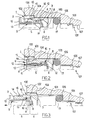
- the circuit element fluid transport system has a body 100 in which is formed a bore generally designated 101 which has an entrance section 102 opening on one side outside the body 100 and the opposite in a section 103 of smaller diameter than the input section 102 and separated from the latter by a shoulder 104.
- Section 103 opens into a section 105 of diameter smaller than that of section 103 and equal to outer diameter of the pipe end.
- the stretch 105 is separated from the section 103 by a shoulder 106 and leads to the opposite side in a section 107 of equal diameter to the inside diameter of the pipe end.
- the circuit element comprises a device for connection to connect an end of bore pipe 101.
- the connecting device comprises an insert tubular generally designated 1 having ends 2 and 3 between which extends a bore 4.
- the bore 4 comprises in a known manner in itself a entrance section 5 from the end 2 side and a section exit 6 from the end 3 side.
- the entrance section 5 is cylindrical in shape and the outlet section 6 is frustoconical shape flaring towards the entrance section 5.
- the exit section has a large section of more large diameter as the inlet section, connected to it by a shoulder 7.
- the attachment washer 8 known in itself, is frustoconical in shape and has an outer circumference received in the large section of the output section 6 in the vicinity of the shoulder 7.
- the shackle 8 has an inner circumference divided so known in teeth intended to bite the outer surface from the driving end.
- the lock washer 8 is deformable between a state of rest or state of attachment in which it delimits a lower inside diameter at the outside diameter of the pipe end and a state of liberation in which it delimits a inside diameter greater than the outside diameter of the driving end.
- a tubular pusher generally designated 9 is received in the input section 5.
- the pusher 9 is used to the disconnection of the pipe end.
- the pusher 9 comprises an end 10 intended to protrude from the bore 101 and one end 11 opposite received in the insert 1.
- the end 11 of the pusher 9 is provided externally of a redan 12 cooperating with a redan 13 of the insert 1 holding the pusher 9 in the insert 1.
- the redan 12 has on the side of the outlet section 6 an inclined face allowing insertion of the pusher into the insert.
- the pusher 9 is slidably movable in the insert 1 between a first driving position or rest position in which the nose of the pusher 9 is away from the lock washer 8 in its hooking state and a second driving position in which the nose of the pusher 9 is strongly against the attachment washer 8 and deforms it in his state of liberation.
- Insert 1 is externally provided with a throat 14 in which is received the inner circumference of a anchor washer 15 whose outer circumference is divided into teeth intended to bite the surface of the bore 101.
- the anchor washer 15 is of conventional shape frustoconical and is plastically deformable between a state Anchor in which the teeth delimit a diameter greater than the diameter of the inlet section 102 of the bore 101 and a free passage state in which the teeth delimit an outside diameter less than the diameter of the entrance section 102.
- the insert 1 Downstream of the washer 15 by reference to a direction depressing the connecting device in the bore 101, the insert 1 comprises an external projection of annular form forming a stop 16 intended to come into contact of the shoulder 104.
- a sealing element 17 is received in the section intermediate 103 in the vicinity of the shoulder 106.
- the sealing element 17 is annular and present an internal diameter slightly less than the diameter outer end of pipe and outer diameter slightly larger than the diameter of the intermediate section 103.
- connection device is introduced in the bore 101 by the end 3 of the insert 1, the operator exerting the insertion force on the pusher 9.
- the insertion force is continued until the stop 16 comes into contact with the shoulder 104.
- the insert 1 is then in anchoring position ( Figure 1).
- the anchor washer 15 allows by its shape the insertion of the insert but opposes any withdrawal, the teeth bracing and penetrating into the surface of the bore 101.
- the pusher 9 Prior to the actual withdrawal, the pusher 9 is subjected to a significant driving force by example by applying a mallet to him (see figure 2).
- the stop 16 is of low height. It can be provided continuous or in segments for example breakable so that a continuation of the insertion of the insert 1 is rendered possible. This stop can also be plastically deformable so as to pass deformed without too much friction, in the intermediate section 103.
- the movement continuing, the anchor washer 15 comes into stop against the shoulder 104 which deforms the washer anchor 15 in its free passage state.
- the insert 1 is then in the release position ( Figure 2).
- the space separating the end 3 and the sealing element 17 when the insert 1 is in its anchoring position must be sufficient to allow the embedding of the insert in its release position.
- connection device can then be extracted of the bore by pulling on the pusher 9 which causes the insert 1, the anchor washer 15 retaining its state of free passage because of its plasticity (figure 3).
- Means for holding the anchor washer in his state of free passage are here constituted by the geometry of the anchor washer and the structure internal material of the anchor washer that confer to the latter its ability to deform plastically.
- connection device comprises an insert 21 having an outer shape identical to that of the insert 1 described above, that is to say with one end 22 and one end 23 and a groove 14 formed externally to receive an anchor washer 15 downstream of which by reference to a direction of depression extends a stop 16.
- a bore 25 having an inlet portion 26 of cylindrical shape and an outlet section 27 connecting to the entrance section 26 by a frustoconical portion flaring away from the entrance section 26.
- the pusher 9 and the snap washer 8 are replaced by a designated clamp generally in 28 and known in itself.
- the clamp 28 includes an end 29 extending protruding from the end 22 of the insert 21, a portion central extending into the inlet section 26 of the bore 25 and one end 30 extending into the stretch of outlet 27 of the bore 25.
- the end 30 has a shape frustoconical designed to cooperate with the frustoconical portion of the output section 27 so that an effort extraction exerted on the clamp 28 causes a narrowing elastic of the passage section defined by end 30. Such an extraction effort results in example of a recoil of the driving end and causes clamping the pipe end by the clamp 28.
- An O-ring 17 is as in the first embodiment disposed in the intermediate section 103 in the vicinity of the shoulder 106. As in the first embodiment, the distance separating the end 23 of the insert 21 and the sealing element 17 must be sufficient to allow insertion of the insert 21 to a release position in the intermediate section 103.
- Set up, operation and removal connecting device are identical to those of the connecting device of the first embodiment.
- the element 17 is replaced by a first element 31 located in the outlet section 27 of the bore 25 of the insert 21, and by a second element seal 32 received in an outer groove 33 of a terminal portion 34 extending the end 23 of the insert 21.
- the sealing element 31 is arranged to ensure sealing the connection between the pipe end and the insert 21 while the sealing member 32 is intended to seal the connection between the insert 21 and the body 100.
- Set up, operation and removal connecting device are identical to those of the connecting device of the first embodiment.
- the puck anchor 15 is received in a groove 35 of the portion terminal 34 downstream of the sealing member 32 by reference to a direction of depression in the bore 101, the inlet portion 102 of the bore 101 being elongated by compared to that of the first embodiment and the two previous variants.
- the stop 16 is replaced by a stop 36 which bears on an outer surface of the surrounding body 100 the outlet of the entrance section 102 outside the body 100.
- Set up, operation and removal connecting device are identical to those of the connecting device of the first embodiment.
- the device for connection of the circuit element according to the second embodiment of the invention differs from the element circuit of the first embodiment that by the nature of the anchor washer used and the absence a stop 16 on the outside of the insert.
- the references used for the circuit element of the second embodiment will therefore be identical to those used for the connecting device of the first embodiment except for the anchor washer that will carry the reference 40 and for a ring that will carry the reference 41 which will be detailed below.
- Washer 40 is different from the anchor washer 15 in that it is elastically deformable and no longer plastically between its anchoring state and its state of free passage.
- a ring 4 ' Downstream of the anchor washer 40, a ring 4 ' is slidably mounted on the insert 1 between a position of rest in which the ring 41 extends over the outer portion of the insert 1 adjacent to the groove 14 and an active position in which the ring 41 extends above throat 14.
- the installation of the connecting device according to the second embodiment is carried out as that of the first embodiment, the insertion effort being interrupted when the ring 41 in its first position reaches the abutment of the shoulder 104 (FIG. 7).
- the ring 41 can be slightly glued on the insert 1 creating a connection that can "let go” under a determined effort.
- This ring can also be supported on the insert by a stop such than that 16 of the preceding figures located at the right of the front flank of the throat. place a kind of snap circlips to form a shoulder "erasable".
- the removal of the connecting device is realized by pressing the pusher 9 so as to cause a displacement of the insert 1 in the bore 101 according to a sink direction of it until the ring 41, which is fixed relative to the bore 101, arrives in its second position by deforming the anchor washer 15 in its state of free passage (Figure 8).
- the washer anchor By bringing the ring 41 back into position, the washer anchor returns to its anchored state, which allows reuse of the connection device.
Landscapes
- Engineering & Computer Science (AREA)
- General Engineering & Computer Science (AREA)
- Mechanical Engineering (AREA)
- Quick-Acting Or Multi-Walled Pipe Joints (AREA)
- Ink Jet (AREA)
- Separation Using Semi-Permeable Membranes (AREA)
- Infusion, Injection, And Reservoir Apparatuses (AREA)
Applications Claiming Priority (2)
| Application Number | Priority Date | Filing Date | Title |
|---|---|---|---|
| FR0404436 | 2004-04-27 | ||
| FR0404436A FR2869385B1 (fr) | 2004-04-27 | 2004-04-27 | Element de circuit de transport de fluide equipe d'un dispositif de raccordement de type cartouche |
Publications (2)
| Publication Number | Publication Date |
|---|---|
| EP1591709A1 true EP1591709A1 (de) | 2005-11-02 |
| EP1591709B1 EP1591709B1 (de) | 2007-06-20 |
Family
ID=34942085
Family Applications (1)
| Application Number | Title | Priority Date | Filing Date |
|---|---|---|---|
| EP05290771A Expired - Lifetime EP1591709B1 (de) | 2004-04-27 | 2005-04-07 | Flüssigkeitskreislaufselement ausgerüstet mit einer patronenartigen Anschlußvorrichtung |
Country Status (5)
| Country | Link |
|---|---|
| US (1) | US7448654B2 (de) |
| EP (1) | EP1591709B1 (de) |
| AT (1) | ATE365294T1 (de) |
| DE (1) | DE602005001418T2 (de) |
| FR (1) | FR2869385B1 (de) |
Cited By (4)
| Publication number | Priority date | Publication date | Assignee | Title |
|---|---|---|---|---|
| WO2011003779A1 (fr) * | 2009-07-08 | 2011-01-13 | Legris Sas | Embout d'insertion pour raccord ou analogue a faible effort d'emmanchement |
| WO2011003778A1 (fr) * | 2009-07-08 | 2011-01-13 | Legris Sas | Embout d'insertion pour raccord ou analogue demontable par devissage |
| FR2958713A1 (fr) * | 2010-04-13 | 2011-10-14 | Legris Sas | Dispositif de raccordement d'un tube a un element de circuit, procede de montage d'une rondelle d'ancrage sur un corps d'un tel dispositif de raccordement et procede de demontage d'un tel dispositif |
| IT201900002131A1 (it) * | 2019-02-14 | 2020-08-14 | Tosi F Lli S R L | Assieme di raccordo ad innesto rapido e corpo di un elemento circuitale e relativo circuito pneumatico. |
Families Citing this family (20)
| Publication number | Priority date | Publication date | Assignee | Title |
|---|---|---|---|---|
| US8205915B1 (en) | 2007-05-25 | 2012-06-26 | Quick Fitting, Inc. | Piping joint assembly system and method |
| US8480134B2 (en) | 2007-05-25 | 2013-07-09 | Quick Fitting, Inc. | Piping joint assembly system and method with sealing ring stabilizer |
| US8398122B2 (en) | 2010-12-30 | 2013-03-19 | Quick Fitting, Inc. | Push connect joint assembly, system and method |
| US8801048B2 (en) | 2012-11-27 | 2014-08-12 | Charlotte Pipe And Foundry Company | Mechanical pipe coupling assembly without adhesive or bonding agent |
| US9447906B2 (en) | 2013-12-11 | 2016-09-20 | Nibco Inc. | Self-locking push-to-connect insert |
| US9541228B2 (en) * | 2013-12-11 | 2017-01-10 | Nibco Inc. | Push-to-connect fitting |
| US10006575B2 (en) | 2013-12-11 | 2018-06-26 | Nibco Inc. | Modular push-to-connect assembly |
| US9777875B2 (en) | 2014-02-26 | 2017-10-03 | Nibco Inc. | Clam shell push-to-connect assembly |
| US9879810B2 (en) | 2015-09-18 | 2018-01-30 | Quick Fitting, Inc. | Push-to-connect joint assembly with protective shield device and method |
| US9562637B1 (en) | 2015-09-22 | 2017-02-07 | Quick Fitting, Inc. | Locking pipe joint assembly, device and method |
| US10670173B2 (en) | 2016-03-31 | 2020-06-02 | Quick Fitting, Inc. | Locking pipe joint device with indicator |
| US9671049B1 (en) | 2016-07-27 | 2017-06-06 | Quick Fitting, Inc. | Hybrid push-to-connect fitting device and assembly |
| US10400929B2 (en) | 2017-09-27 | 2019-09-03 | Quick Fitting, Inc. | Fitting device, arrangement and method |
| EP3948042B1 (de) | 2019-04-01 | 2025-01-08 | Swagelok Company | Push-to-connect-anschlussbaugruppen für leitungen und anordnungen |
| US11149426B2 (en) | 2019-06-12 | 2021-10-19 | Charlotte Pipe And Foundry Company | Toilet assembly having improved closet flange |
| US10969047B1 (en) | 2020-01-29 | 2021-04-06 | Quick Fitting Holding Company, Llc | Electrical conduit fitting and assembly |
| US11035510B1 (en) | 2020-01-31 | 2021-06-15 | Quick Fitting Holding Company, Llc | Electrical conduit fitting and assembly |
| US11105452B1 (en) | 2021-02-25 | 2021-08-31 | Quick Fitting Holding Company, Llc | Push-to-connect joint assembly and device |
| US11262011B1 (en) * | 2021-05-17 | 2022-03-01 | Quick Fitting Holding Company, Llc | Swage connector device, assembly and method |
| IT202300001476A1 (it) * | 2023-01-31 | 2024-07-31 | Camozzi Automation S P A | Dispositivo di raccordo a cartuccia |
Citations (2)
| Publication number | Priority date | Publication date | Assignee | Title |
|---|---|---|---|---|
| US3447819A (en) * | 1966-12-30 | 1969-06-03 | Adolph W Borsum | Push-pull connector having combined seal and locking ring |
| US3731955A (en) * | 1971-09-24 | 1973-05-08 | A Borsum | Push-pull connector having a shear-resistant locking ring |
Family Cites Families (6)
| Publication number | Priority date | Publication date | Assignee | Title |
|---|---|---|---|---|
| US4610468A (en) * | 1984-08-14 | 1986-09-09 | United Technologies Automotive, Inc. | Quick connect/disconnect coupling |
| US5505501A (en) * | 1993-06-21 | 1996-04-09 | Seabra; Helio L. | Pressurized connection for a brake system of an automotive vehicle |
| GB9614994D0 (en) * | 1996-07-17 | 1996-09-04 | Guest John D | Improvements in or relating to coupling bodies |
| JP2001050457A (ja) * | 1999-08-03 | 2001-02-23 | Smc Corp | 管継手 |
| FR2830071B1 (fr) * | 2001-09-21 | 2003-11-14 | Legris Sa | Dispositif de raccordement instantane |
| JP4110520B2 (ja) * | 2002-10-23 | 2008-07-02 | Smc株式会社 | 管継手 |
-
2004
- 2004-04-27 FR FR0404436A patent/FR2869385B1/fr not_active Expired - Fee Related
-
2005
- 2005-04-07 DE DE602005001418T patent/DE602005001418T2/de not_active Expired - Lifetime
- 2005-04-07 EP EP05290771A patent/EP1591709B1/de not_active Expired - Lifetime
- 2005-04-07 AT AT05290771T patent/ATE365294T1/de not_active IP Right Cessation
- 2005-04-27 US US11/115,273 patent/US7448654B2/en not_active Expired - Fee Related
Patent Citations (2)
| Publication number | Priority date | Publication date | Assignee | Title |
|---|---|---|---|---|
| US3447819A (en) * | 1966-12-30 | 1969-06-03 | Adolph W Borsum | Push-pull connector having combined seal and locking ring |
| US3731955A (en) * | 1971-09-24 | 1973-05-08 | A Borsum | Push-pull connector having a shear-resistant locking ring |
Cited By (9)
| Publication number | Priority date | Publication date | Assignee | Title |
|---|---|---|---|---|
| WO2011003779A1 (fr) * | 2009-07-08 | 2011-01-13 | Legris Sas | Embout d'insertion pour raccord ou analogue a faible effort d'emmanchement |
| WO2011003778A1 (fr) * | 2009-07-08 | 2011-01-13 | Legris Sas | Embout d'insertion pour raccord ou analogue demontable par devissage |
| FR2947888A1 (fr) * | 2009-07-08 | 2011-01-14 | Legris Sas | Embout d'insertion pour raccord ou analogue demontable par devissage |
| FR2947889A1 (fr) * | 2009-07-08 | 2011-01-14 | Legris Sas | Embout d'insertion pour raccord ou analogue a faible effort d'emmanchement |
| US9279528B2 (en) | 2009-07-08 | 2016-03-08 | Parker-Hannifin Manufacturing France | Insertion end fitting for a coupling or the like requiring a low push-together force |
| FR2958713A1 (fr) * | 2010-04-13 | 2011-10-14 | Legris Sas | Dispositif de raccordement d'un tube a un element de circuit, procede de montage d'une rondelle d'ancrage sur un corps d'un tel dispositif de raccordement et procede de demontage d'un tel dispositif |
| WO2011128390A1 (fr) * | 2010-04-13 | 2011-10-20 | Parker Hannifin France Sas | Dispositif de raccordement d'un tube a un element de circuit, procede de montage d'une rondelle d'ancrage sur un corps d'un tel dispositif de raccordement et procede de demontage d'un tel dispositif |
| US8844980B2 (en) | 2010-04-13 | 2014-09-30 | Parker Hannifin Manufacturing France Sas | Device for coupling a tube to a circuit element, method for mounting an anchoring ring on a body of such a coupling device and method for dismantling such a device |
| IT201900002131A1 (it) * | 2019-02-14 | 2020-08-14 | Tosi F Lli S R L | Assieme di raccordo ad innesto rapido e corpo di un elemento circuitale e relativo circuito pneumatico. |
Also Published As
| Publication number | Publication date |
|---|---|
| FR2869385B1 (fr) | 2006-11-03 |
| DE602005001418T2 (de) | 2008-08-14 |
| ATE365294T1 (de) | 2007-07-15 |
| DE602005001418D1 (de) | 2007-08-02 |
| US20050242572A1 (en) | 2005-11-03 |
| EP1591709B1 (de) | 2007-06-20 |
| US7448654B2 (en) | 2008-11-11 |
| FR2869385A1 (fr) | 2005-10-28 |
Similar Documents
| Publication | Publication Date | Title |
|---|---|---|
| EP1591709B1 (de) | Flüssigkeitskreislaufselement ausgerüstet mit einer patronenartigen Anschlußvorrichtung | |
| EP1427959B1 (de) | Schnellverbindungsvorrichtung | |
| EP0723103B1 (de) | Vorrichtung zum schnellen Verbinden eines Rohres mit einem starren Element | |
| EP2558763B1 (de) | Vorrichtung zur kopplung eines rohrs an ein schaltelement und verfahren zur demontage solch einer vorrichtung | |
| EP1087168B1 (de) | Vorrichtung zum Verbinden von einem Leitungsende mit einem Anschlussteil | |
| EP1328750B1 (de) | Anschlussanordnung mit einer schnellkupplung zum verbinden von einem leitungsende mit einem anschlussteil und vorrichtung zum schutz der verbindung | |
| EP0715111B1 (de) | Schnellverbindungsvorrichtung zum Kuppeln eines Rohres auf einem starren Ansatzstück | |
| EP1440271B1 (de) | Kopplungsvorrichtung | |
| EP2817548B1 (de) | Vorrichtung für abgedichtete kopplung ohne einen haltebereich | |
| EP2387681B1 (de) | Vorrichtung zur verankerung eines elements in einer öffnung in einer wand und mit solch einer vorrichtung ausgestatteter verbinder | |
| FR2939863A1 (fr) | Dispositif de raccordement epuipe de moyens instantane ou quasi-instantane | |
| FR2810087A1 (fr) | Element pourvu exterieurement de moyens pour cooperer avec un taraudage | |
| FR2876774A1 (fr) | Cartouche de raccordement demontable | |
| WO2006000678A1 (fr) | Dispositif de raccordement de type cartouche et dispositif d'extraction d'un tel dispositif de raccordement | |
| EP1155255A1 (de) | Verbindungsvorrichtung für den anschluss einer leitung an ein element | |
| FR2661452A1 (fr) | Ensemble d'ancrage pour trou fore et procede de fixation d'un tel ensemble. | |
| EP1686306B1 (de) | Herausziehbare Verbindungsvorrichtung | |
| FR2788581A1 (fr) | Ensemble de connexion d'une extremite de conduite a un element | |
| FR2735844A1 (fr) | Dispositif de raccordement rapide d'un tube a un element rigide | |
| FR2876613A1 (fr) | Procede d'extraction d'une cartouche de raccordement et outil pour la mise en oeuvre de celui-ci | |
| WO2016162432A1 (fr) | Dispositif de raccordement a joint mobile pour tube chanfreine | |
| FR2938625A1 (fr) | Dispositif de raccordement ayant des zones inversees d'etancheite et d'accrochage. | |
| FR2978999A1 (fr) | Corps implantable dans un puits et pourvu des moyens de son extraction | |
| EP0336866A1 (de) | Trennbare Rohrkupplung | |
| WO2001013024A1 (fr) | Dispositif de connexion d'un tronçon de canalisation rigide a un organe |
Legal Events
| Date | Code | Title | Description |
|---|---|---|---|
| PUAI | Public reference made under article 153(3) epc to a published international application that has entered the european phase |
Free format text: ORIGINAL CODE: 0009012 |
|
| AK | Designated contracting states |
Kind code of ref document: A1 Designated state(s): AT BE BG CH CY CZ DE DK EE ES FI FR GB GR HU IE IS IT LI LT LU MC NL PL PT RO SE SI SK TR |
|
| AX | Request for extension of the european patent |
Extension state: AL BA HR LV MK YU |
|
| 17P | Request for examination filed |
Effective date: 20060327 |
|
| AKX | Designation fees paid |
Designated state(s): AT BE BG CH CY CZ DE DK EE ES FI FR GB GR HU IE IS IT LI LT LU MC NL PL PT RO SE SI SK TR |
|
| GRAP | Despatch of communication of intention to grant a patent |
Free format text: ORIGINAL CODE: EPIDOSNIGR1 |
|
| GRAS | Grant fee paid |
Free format text: ORIGINAL CODE: EPIDOSNIGR3 |
|
| GRAA | (expected) grant |
Free format text: ORIGINAL CODE: 0009210 |
|
| AK | Designated contracting states |
Kind code of ref document: B1 Designated state(s): AT BE BG CH CY CZ DE DK EE ES FI FR GB GR HU IE IS IT LI LT LU MC NL PL PT RO SE SI SK TR |
|
| REG | Reference to a national code |
Ref country code: GB Ref legal event code: FG4D Free format text: NOT ENGLISH |
|
| REG | Reference to a national code |
Ref country code: CH Ref legal event code: EP |
|
| GBT | Gb: translation of ep patent filed (gb section 77(6)(a)/1977) |
Effective date: 20070704 |
|
| REG | Reference to a national code |
Ref country code: IE Ref legal event code: FG4D Free format text: LANGUAGE OF EP DOCUMENT: FRENCH |
|
| REF | Corresponds to: |
Ref document number: 602005001418 Country of ref document: DE Date of ref document: 20070802 Kind code of ref document: P |
|
| PG25 | Lapsed in a contracting state [announced via postgrant information from national office to epo] |
Ref country code: SE Free format text: LAPSE BECAUSE OF FAILURE TO SUBMIT A TRANSLATION OF THE DESCRIPTION OR TO PAY THE FEE WITHIN THE PRESCRIBED TIME-LIMIT Effective date: 20070920 |
|
| PG25 | Lapsed in a contracting state [announced via postgrant information from national office to epo] |
Ref country code: PL Free format text: LAPSE BECAUSE OF FAILURE TO SUBMIT A TRANSLATION OF THE DESCRIPTION OR TO PAY THE FEE WITHIN THE PRESCRIBED TIME-LIMIT Effective date: 20070620 Ref country code: AT Free format text: LAPSE BECAUSE OF FAILURE TO SUBMIT A TRANSLATION OF THE DESCRIPTION OR TO PAY THE FEE WITHIN THE PRESCRIBED TIME-LIMIT Effective date: 20070620 |
|
| NLV1 | Nl: lapsed or annulled due to failure to fulfill the requirements of art. 29p and 29m of the patents act | ||
| REG | Reference to a national code |
Ref country code: IE Ref legal event code: FD4D |
|
| PG25 | Lapsed in a contracting state [announced via postgrant information from national office to epo] |
Ref country code: PT Free format text: LAPSE BECAUSE OF FAILURE TO SUBMIT A TRANSLATION OF THE DESCRIPTION OR TO PAY THE FEE WITHIN THE PRESCRIBED TIME-LIMIT Effective date: 20071120 Ref country code: IS Free format text: LAPSE BECAUSE OF FAILURE TO SUBMIT A TRANSLATION OF THE DESCRIPTION OR TO PAY THE FEE WITHIN THE PRESCRIBED TIME-LIMIT Effective date: 20071020 Ref country code: ES Free format text: LAPSE BECAUSE OF FAILURE TO SUBMIT A TRANSLATION OF THE DESCRIPTION OR TO PAY THE FEE WITHIN THE PRESCRIBED TIME-LIMIT Effective date: 20071001 Ref country code: BG Free format text: LAPSE BECAUSE OF FAILURE TO SUBMIT A TRANSLATION OF THE DESCRIPTION OR TO PAY THE FEE WITHIN THE PRESCRIBED TIME-LIMIT Effective date: 20070920 Ref country code: SI Free format text: LAPSE BECAUSE OF FAILURE TO SUBMIT A TRANSLATION OF THE DESCRIPTION OR TO PAY THE FEE WITHIN THE PRESCRIBED TIME-LIMIT Effective date: 20070620 Ref country code: CZ Free format text: LAPSE BECAUSE OF FAILURE TO SUBMIT A TRANSLATION OF THE DESCRIPTION OR TO PAY THE FEE WITHIN THE PRESCRIBED TIME-LIMIT Effective date: 20070620 Ref country code: NL Free format text: LAPSE BECAUSE OF FAILURE TO SUBMIT A TRANSLATION OF THE DESCRIPTION OR TO PAY THE FEE WITHIN THE PRESCRIBED TIME-LIMIT Effective date: 20070620 Ref country code: IE Free format text: LAPSE BECAUSE OF FAILURE TO SUBMIT A TRANSLATION OF THE DESCRIPTION OR TO PAY THE FEE WITHIN THE PRESCRIBED TIME-LIMIT Effective date: 20070620 |
|
| PG25 | Lapsed in a contracting state [announced via postgrant information from national office to epo] |
Ref country code: LT Free format text: LAPSE BECAUSE OF FAILURE TO SUBMIT A TRANSLATION OF THE DESCRIPTION OR TO PAY THE FEE WITHIN THE PRESCRIBED TIME-LIMIT Effective date: 20070620 Ref country code: SK Free format text: LAPSE BECAUSE OF FAILURE TO SUBMIT A TRANSLATION OF THE DESCRIPTION OR TO PAY THE FEE WITHIN THE PRESCRIBED TIME-LIMIT Effective date: 20070620 |
|
| PLBE | No opposition filed within time limit |
Free format text: ORIGINAL CODE: 0009261 |
|
| STAA | Information on the status of an ep patent application or granted ep patent |
Free format text: STATUS: NO OPPOSITION FILED WITHIN TIME LIMIT |
|
| PG25 | Lapsed in a contracting state [announced via postgrant information from national office to epo] |
Ref country code: GR Free format text: LAPSE BECAUSE OF FAILURE TO SUBMIT A TRANSLATION OF THE DESCRIPTION OR TO PAY THE FEE WITHIN THE PRESCRIBED TIME-LIMIT Effective date: 20070921 Ref country code: DE Free format text: LAPSE BECAUSE OF FAILURE TO SUBMIT A TRANSLATION OF THE DESCRIPTION OR TO PAY THE FEE WITHIN THE PRESCRIBED TIME-LIMIT Effective date: 20070921 Ref country code: DK Free format text: LAPSE BECAUSE OF FAILURE TO SUBMIT A TRANSLATION OF THE DESCRIPTION OR TO PAY THE FEE WITHIN THE PRESCRIBED TIME-LIMIT Effective date: 20070620 |
|
| 26N | No opposition filed |
Effective date: 20080325 |
|
| PG25 | Lapsed in a contracting state [announced via postgrant information from national office to epo] |
Ref country code: RO Free format text: LAPSE BECAUSE OF FAILURE TO SUBMIT A TRANSLATION OF THE DESCRIPTION OR TO PAY THE FEE WITHIN THE PRESCRIBED TIME-LIMIT Effective date: 20070620 |
|
| BERE | Be: lapsed |
Owner name: LEGRIS SA Effective date: 20080430 |
|
| PG25 | Lapsed in a contracting state [announced via postgrant information from national office to epo] |
Ref country code: MC Free format text: LAPSE BECAUSE OF NON-PAYMENT OF DUE FEES Effective date: 20080430 |
|
| PG25 | Lapsed in a contracting state [announced via postgrant information from national office to epo] |
Ref country code: EE Free format text: LAPSE BECAUSE OF FAILURE TO SUBMIT A TRANSLATION OF THE DESCRIPTION OR TO PAY THE FEE WITHIN THE PRESCRIBED TIME-LIMIT Effective date: 20070620 |
|
| PG25 | Lapsed in a contracting state [announced via postgrant information from national office to epo] |
Ref country code: FI Free format text: LAPSE BECAUSE OF FAILURE TO SUBMIT A TRANSLATION OF THE DESCRIPTION OR TO PAY THE FEE WITHIN THE PRESCRIBED TIME-LIMIT Effective date: 20070620 |
|
| PG25 | Lapsed in a contracting state [announced via postgrant information from national office to epo] |
Ref country code: BE Free format text: LAPSE BECAUSE OF NON-PAYMENT OF DUE FEES Effective date: 20080430 |
|
| PG25 | Lapsed in a contracting state [announced via postgrant information from national office to epo] |
Ref country code: CY Free format text: LAPSE BECAUSE OF FAILURE TO SUBMIT A TRANSLATION OF THE DESCRIPTION OR TO PAY THE FEE WITHIN THE PRESCRIBED TIME-LIMIT Effective date: 20070620 |
|
| REG | Reference to a national code |
Ref country code: CH Ref legal event code: PL |
|
| PG25 | Lapsed in a contracting state [announced via postgrant information from national office to epo] |
Ref country code: LI Free format text: LAPSE BECAUSE OF NON-PAYMENT OF DUE FEES Effective date: 20090430 Ref country code: CH Free format text: LAPSE BECAUSE OF NON-PAYMENT OF DUE FEES Effective date: 20090430 |
|
| PG25 | Lapsed in a contracting state [announced via postgrant information from national office to epo] |
Ref country code: LU Free format text: LAPSE BECAUSE OF NON-PAYMENT OF DUE FEES Effective date: 20080407 Ref country code: HU Free format text: LAPSE BECAUSE OF FAILURE TO SUBMIT A TRANSLATION OF THE DESCRIPTION OR TO PAY THE FEE WITHIN THE PRESCRIBED TIME-LIMIT Effective date: 20071221 |
|
| PG25 | Lapsed in a contracting state [announced via postgrant information from national office to epo] |
Ref country code: TR Free format text: LAPSE BECAUSE OF FAILURE TO SUBMIT A TRANSLATION OF THE DESCRIPTION OR TO PAY THE FEE WITHIN THE PRESCRIBED TIME-LIMIT Effective date: 20070620 |
|
| PGFP | Annual fee paid to national office [announced via postgrant information from national office to epo] |
Ref country code: DE Payment date: 20110407 Year of fee payment: 7 Ref country code: GB Payment date: 20110323 Year of fee payment: 7 |
|
| PGFP | Annual fee paid to national office [announced via postgrant information from national office to epo] |
Ref country code: IT Payment date: 20110423 Year of fee payment: 7 |
|
| GBPC | Gb: european patent ceased through non-payment of renewal fee |
Effective date: 20120407 |
|
| PG25 | Lapsed in a contracting state [announced via postgrant information from national office to epo] |
Ref country code: GB Free format text: LAPSE BECAUSE OF NON-PAYMENT OF DUE FEES Effective date: 20120407 |
|
| REG | Reference to a national code |
Ref country code: DE Ref legal event code: R119 Ref document number: 602005001418 Country of ref document: DE Effective date: 20121101 |
|
| PG25 | Lapsed in a contracting state [announced via postgrant information from national office to epo] |
Ref country code: IT Free format text: LAPSE BECAUSE OF NON-PAYMENT OF DUE FEES Effective date: 20120407 |
|
| PG25 | Lapsed in a contracting state [announced via postgrant information from national office to epo] |
Ref country code: DE Free format text: LAPSE BECAUSE OF FAILURE TO SUBMIT A TRANSLATION OF THE DESCRIPTION OR TO PAY THE FEE WITHIN THE PRESCRIBED TIME-LIMIT Effective date: 20121101 |
|
| REG | Reference to a national code |
Ref country code: FR Ref legal event code: PLFP Year of fee payment: 12 |
|
| REG | Reference to a national code |
Ref country code: FR Ref legal event code: PLFP Year of fee payment: 13 |
|
| REG | Reference to a national code |
Ref country code: FR Ref legal event code: PLFP Year of fee payment: 14 |
|
| P01 | Opt-out of the competence of the unified patent court (upc) registered |
Effective date: 20230525 |
|
| PGFP | Annual fee paid to national office [announced via postgrant information from national office to epo] |
Ref country code: FR Payment date: 20240423 Year of fee payment: 20 |