EP1591747A2 - Zünder mit einer internen Hülse zur Verankerung einer pyrotechnischen Ladung und Verfahren zur Herstellung desselben - Google Patents
Zünder mit einer internen Hülse zur Verankerung einer pyrotechnischen Ladung und Verfahren zur Herstellung desselben Download PDFInfo
- Publication number
- EP1591747A2 EP1591747A2 EP05105744A EP05105744A EP1591747A2 EP 1591747 A2 EP1591747 A2 EP 1591747A2 EP 05105744 A EP05105744 A EP 05105744A EP 05105744 A EP05105744 A EP 05105744A EP 1591747 A2 EP1591747 A2 EP 1591747A2
- Authority
- EP
- European Patent Office
- Prior art keywords
- charge
- sleeve
- eyelet
- initiator
- header assembly
- Prior art date
- Legal status (The legal status is an assumption and is not a legal conclusion. Google has not performed a legal analysis and makes no representation as to the accuracy of the status listed.)
- Withdrawn
Links
- 239000003999 initiator Substances 0.000 title claims abstract description 33
- 238000000034 method Methods 0.000 title claims description 19
- 239000002002 slurry Substances 0.000 claims description 24
- 230000000977 initiatory effect Effects 0.000 claims description 7
- 239000007788 liquid Substances 0.000 claims description 5
- 238000003466 welding Methods 0.000 claims description 2
- 230000014759 maintenance of location Effects 0.000 abstract description 3
- 238000007596 consolidation process Methods 0.000 description 5
- 239000011521 glass Substances 0.000 description 5
- 239000011230 binding agent Substances 0.000 description 4
- 238000001035 drying Methods 0.000 description 4
- 229910052751 metal Inorganic materials 0.000 description 4
- 239000002184 metal Substances 0.000 description 4
- 239000010964 304L stainless steel Substances 0.000 description 3
- QCWXUUIWCKQGHC-UHFFFAOYSA-N Zirconium Chemical compound [Zr] QCWXUUIWCKQGHC-UHFFFAOYSA-N 0.000 description 3
- AXZAYXJCENRGIM-UHFFFAOYSA-J dipotassium;tetrabromoplatinum(2-) Chemical compound [K+].[K+].[Br-].[Br-].[Br-].[Br-].[Pt+2] AXZAYXJCENRGIM-UHFFFAOYSA-J 0.000 description 3
- 229910001487 potassium perchlorate Inorganic materials 0.000 description 3
- 239000002904 solvent Substances 0.000 description 3
- 239000000758 substrate Substances 0.000 description 3
- 229910052726 zirconium Inorganic materials 0.000 description 3
- DKPFZGUDAPQIHT-UHFFFAOYSA-N Butyl acetate Natural products CCCCOC(C)=O DKPFZGUDAPQIHT-UHFFFAOYSA-N 0.000 description 2
- 229920000459 Nitrile rubber Polymers 0.000 description 2
- 239000004677 Nylon Substances 0.000 description 2
- 239000000654 additive Substances 0.000 description 2
- 239000000919 ceramic Substances 0.000 description 2
- 230000006835 compression Effects 0.000 description 2
- 238000007906 compression Methods 0.000 description 2
- FUZZWVXGSFPDMH-UHFFFAOYSA-N hexanoic acid Chemical compound CCCCCC(O)=O FUZZWVXGSFPDMH-UHFFFAOYSA-N 0.000 description 2
- 239000012212 insulator Substances 0.000 description 2
- 229920001778 nylon Polymers 0.000 description 2
- 230000000717 retained effect Effects 0.000 description 2
- 239000007787 solid Substances 0.000 description 2
- 229910000503 Na-aluminosilicate Inorganic materials 0.000 description 1
- XUIMIQQOPSSXEZ-UHFFFAOYSA-N Silicon Chemical compound [Si] XUIMIQQOPSSXEZ-UHFFFAOYSA-N 0.000 description 1
- 239000000853 adhesive Substances 0.000 description 1
- 230000001070 adhesive effect Effects 0.000 description 1
- 229910052910 alkali metal silicate Inorganic materials 0.000 description 1
- 230000003466 anti-cipated effect Effects 0.000 description 1
- 229910052788 barium Inorganic materials 0.000 description 1
- DSAJWYNOEDNPEQ-UHFFFAOYSA-N barium atom Chemical compound [Ba] DSAJWYNOEDNPEQ-UHFFFAOYSA-N 0.000 description 1
- 230000015572 biosynthetic process Effects 0.000 description 1
- 239000004020 conductor Substances 0.000 description 1
- 238000010276 construction Methods 0.000 description 1
- 230000008602 contraction Effects 0.000 description 1
- 238000009792 diffusion process Methods 0.000 description 1
- 230000006353 environmental stress Effects 0.000 description 1
- 238000010304 firing Methods 0.000 description 1
- 238000004519 manufacturing process Methods 0.000 description 1
- 229910001092 metal group alloy Inorganic materials 0.000 description 1
- 239000000203 mixture Substances 0.000 description 1
- 229910001120 nichrome Inorganic materials 0.000 description 1
- 229910000623 nickel–chromium alloy Inorganic materials 0.000 description 1
- 239000004033 plastic Substances 0.000 description 1
- ZONODCCBXBRQEZ-UHFFFAOYSA-N platinum tungsten Chemical compound [W].[Pt] ZONODCCBXBRQEZ-UHFFFAOYSA-N 0.000 description 1
- 238000003825 pressing Methods 0.000 description 1
- 238000004080 punching Methods 0.000 description 1
- 238000007789 sealing Methods 0.000 description 1
- 239000004065 semiconductor Substances 0.000 description 1
- 229910052710 silicon Inorganic materials 0.000 description 1
- 239000010703 silicon Substances 0.000 description 1
- 235000012217 sodium aluminium silicate Nutrition 0.000 description 1
- 239000000429 sodium aluminium silicate Substances 0.000 description 1
- URGAHOPLAPQHLN-UHFFFAOYSA-N sodium aluminosilicate Chemical compound [Na+].[Al+3].[O-][Si]([O-])=O.[O-][Si]([O-])=O URGAHOPLAPQHLN-UHFFFAOYSA-N 0.000 description 1
- 239000010935 stainless steel Substances 0.000 description 1
- 229910001220 stainless steel Inorganic materials 0.000 description 1
- 230000035882 stress Effects 0.000 description 1
- 239000011800 void material Substances 0.000 description 1
Images




Classifications
-
- F—MECHANICAL ENGINEERING; LIGHTING; HEATING; WEAPONS; BLASTING
- F42—AMMUNITION; BLASTING
- F42B—EXPLOSIVE CHARGES, e.g. FOR BLASTING, FIREWORKS, AMMUNITION
- F42B3/00—Blasting cartridges, i.e. case and explosive
- F42B3/10—Initiators therefor
- F42B3/12—Bridge initiators
- F42B3/125—Bridge initiators characterised by the configuration of the bridge initiator case
-
- F—MECHANICAL ENGINEERING; LIGHTING; HEATING; WEAPONS; BLASTING
- F42—AMMUNITION; BLASTING
- F42B—EXPLOSIVE CHARGES, e.g. FOR BLASTING, FIREWORKS, AMMUNITION
- F42B3/00—Blasting cartridges, i.e. case and explosive
- F42B3/10—Initiators therefor
- F42B3/195—Manufacture
Definitions
- the present invention generally relates to the field of pyrotechnic initiators, and more particularly to a pyrotechnic initiator having an internal sleeve retaining a pyrotechnic charge.
- Pyrotechnic initiators have many uses in industrial and consumer applications. One important use is in triggering the inflation of airbags in motor vehicles. Significant efforts have been made in the automotive industry to reduce the cost of manufacturing reliable airbag initiators.
- One advance has been the use of liquids and slurries in loading pyrotechnic charges into the initiators. As shown in U.S. Patent No. 5,686,691 to Hamilton et al., it is known to load a slurry charge into a conventionally cup-shaped charge can, and to directly affix such a loaded can onto a header assembly so that the charge comes into contact with the header surface and bridgewire.
- this method poses certain drawbacks and difficulties and limits the available range of slurries since the slurry must be amenable to consolidation. It is believed that hitherto a thin-walled, rigid charge sleeve has not been used to facilitate the loading and durable retention of a pyrotechnic charge in place on the header surface within an initiator.
- an initiator includes an internal charge sleeve that is loaded with a pyrotechnic charge such as through slurry loading.
- the sleeve is closed at its bottom end by the initiator's header assembly, but has an open top end.
- the charge sleeve beneficially retains the charge on the header of the initiator, either in conjunction with the upper interior surface of the charge can, or through the use of a monolithic charge and a narrowed top end of the sleeve.
- an initiator 56 preferably includes a number of features typically found in pyrotechnic initiators.
- a glass-to-metal sealed header assembly 58 hermetically attached to a charge can 42 through a circumferential weld 24, an insulator cup 40, and a molded insulating body 26.
- the depicted header assembly 58 consists of an isolated center pin 22, glass 50, an eyelet 44, a welded Bridgewire 38, and a ground pin 20, with both of the pins 20 and 22 extending beyond the body 26 to form a connector end.
- the eyelet 44 is preferably made of a metal such as 304L stainless steel, and is generally cylindrical with a passage defined through it to permit a feedthrough to be created by the hermetic sealing of the glass 50 and the center pin 22 therein.
- the depicted header assembly 58 includes an eccentrically placed passage, center pin and glass, however, they could alternately be concentrically placed, or the header could be non-coaxial with two pins each sealed in a feedthrough.
- the glass 50 may preferably consist of sodium aluminosilicate or barium alkali silicate, and the bridgewire 38 may be formed from a high resistance metal alloy such as platinum-tungsten or "NICHROME" nickel-chromium alloy.
- the charge 32 may preferably be zirconium/potassium perchlorate-based and is in a heat-receiving relationship with the bridgewire 38.
- a predetermined "no fire” level and duration e.g. 200mA for 10 seconds at 85°C
- a monolithic bridge may be used, and preferably consists of dissimilar conductive materials such as a thick resistive film on a ceramic substrate, a thin resistive film deposited on a ceramic substrate, or a semiconductor junction diffusion doped onto a silicon substrate, examples of each of which are well-known in the art.
- a sleeve 36 having a cylindrical aspect contains the charge 32 within the initiator and retains it in place against the top surface of the header assembly 58, preferably so that it is in intimate contact with the bridgewire 38.
- This sleeve 36 can be formed, for example, from a hollow cylindrical piece of 304L stainless steel having a wall thickness of ten thousandths of an inch, which is then swaged inwardly (using a suitable special-formed tool designed for the application such as is well-known in the art) at its top to form a narrowed top end 52.
- the sleeve 36 can then be slid onto the header assembly 58 and its bottom end 27 can then be swaged inwardly along a suitable corresponding circumferential recess on the eyelet 44.
- the sleeve 36 preferably has a relatively tight interference fit with the header assembly 58 so as to secure it firmly thereto and reduce the likelihood of the charge 32 shifting.
- Approximately the upper half or third of the sleeve 36 preferably remains above the top surface of the header assembly 58.
- Other suitable methods, such as welding, can alternately or additionally be used to secure the sleeve.
- a suitable slurry for use in forming charge 32 in the present embodiment may include a binder such as Viton-B® preferably at less than five percent by weight, a solvent such as butyl acetate at approximately twenty percent by weight, and the balance preferably being zirconium/potassium perchlorate and any other desired additives.
- a binder such as Viton-B® preferably at less than five percent by weight
- a solvent such as butyl acetate at approximately twenty percent by weight
- the balance preferably being zirconium/potassium perchlorate and any other desired additives.
- the upper end 52 of the sleeve 36 can be circumferentially crimped inwardly after (or while) the slurry dries, so that it becomes narrowed and compresses the charge 32.
- the top of the charge 32 can be pressed downwardly during or after drying of the slurry in order to pack it more tightly and more firmly press it against the bridgewire 38.
- such pressing is preferably done in such a way as to produce a concave top on the charge 32 (as shown in Figure 1)
- the top of the charge 32 could alternately be formed substantially flat or even project convexly above the top of the sleeve 36 (similar to the depiction in Figure 5).
- the sleeve 36 is preferably loaded after it is attached to the header assembly as just described, the sleeve 36 could alternately be separately pre-loaded (preferably with a slurry, and preferably upside-down on a flat surface or suitable fixture) with the charge 32 (so as to fill the desired portion of the upper region of the sleeve 36). Then, preferably after substantial or complete drying of the slurry, the header assembly 58 could be slid into the sleeve 36 such that the charge 32 makes intimate contact with the bridgewire 38. This would preferably be done with the sleeve 36 preformed with its narrowed top end 52, and with the application of sufficient pressure on the header assembly 58 against the charge 32 so as to increase the degree of contact therebetween.
- the charge 32 which is a monolithic solid mass, is physically retained in place on the top surface of the header assembly 58 by the sleeve 36.
- the obstruction of the narrowed top end 52 (which has a smaller inner diameter than the outer diameter of charge 32 below narrowed top end 52), and possibly also the cohesion and/or friction between charge 32 and the walls of sleeve 36, retain charge 32 in intimate contact with bridgewire 38 (or other suitable electrical initiating element).
- bridgewire 38 or other suitable electrical initiating element
- the resulting initiator subassembly (including the reader assembly 58 and the sleeve 36 loaded with the pyrotechnic charge 32) is pressed into and hermetically sealed and attached to the charge can 42 (which preferably may also be 304L stainless steel having a wall thickness of ten thousandths of an inch), such as with a through-weld 24.
- the charge can 42 which preferably may also be 304L stainless steel having a wall thickness of ten thousandths of an inch
- a suitable insulator cup 40 (which preferably may be nylon having a wall thickness of ten thousandths of an inch) and insulating body 26 (which may preferably be nylon insert-molded onto the initiator subassembly) may be provided as is well known in the art.
- the intermediary containment provided by the sleeve 36 may also help insulate the charge 32 within the initiator 56 from external physical stresses such as vibrations, particularly if all (as shown in Figure 1) or at least a substantial portion of the sleeve 36 is physically spaced apart from the interior of the can 42. This in turn enhances the robustness of the contact between charge 32 and bridgewire 38.
- a sleeve having a narrowed top end can be made.
- a cup-shaped metal piece can be used to form the sleeve 36a.
- a hole can then be punched or stamped out of the bottom of this cup, in a position corresponding to the feedthrough and bridgewire placement on the surface of the header assembly.
- the narrowed top end of the sleeve 36a can be formed as described above, either before or after the step of punching out the hole in the bottom of the sleeve 36a.
- a circumferential upturned rim can be farmed (again using a suitable special-formed tool) onto the edge of the hole in the bottom of the sleeve 36a, and can beneficially serve as a dam to help locate the loading of, and to retain in contact with the bridgewire 38, a primer charge 34 that is distinct from the (output) charge 32.
- a preferable height for such a rim is ten thousandths of an inch.
- Stainless steel 304L having a wall thickness of ten thousandths of an inch is again suitable for such a sleeve.
- the sleeve 36a is preferably resistance welded at weld 38 to the top surface of the header assembly, although it can also be TIG-welded, laser welded, glued, or attached by any other suitable means.
- a suitable primer charge 34 may be loaded, preferably in a slurry form, and then output charge 32 may be loaded generally as described above with reference to Figure 1.
- R suitable primer charge 34 may be a slurry including a binder such as Nipol® AR53L preferably at a few tenths of a percent by weight, a solvent such as butyl acetate at approximately twenty percent by weight, and the balance preferably being zirconium/potassium perchlorate and any other desired additives.
- the binder in the ignition charge 34 preferably has an extremely high coefficient of elasticity, such as 1000%, and is preferably extremely adhesive so as to strongly bind to the bridgewire.
- the primer charge 34 may preferably have a weight of 30mg.
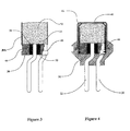
- Figures 3 and 4 show an alternate embodiment of the invention that employs a straight sleeve rather than a sleeve with a narrowed top end.
- Figure 3 shows the loaded sleeve 36b placed on the header assembly 30, ready for the charge can to be placed thereon;
- Figure 4 shows the initiator after the charge can has been pressed down on top of the sleeve, causing the sleeve to slide fully onto the header assembly 30.
- This embodiment may preferably be similar to those of Figures 1 and 2, with the main distinction being that the sleeve 36b does not need a narrowed top end, because the open top of the sleeve is closed off by the interior upper surface of the charge can 42, thus retaining the charge 32 (preferably with a distinct primer charge 34) firmly in place on the top surface of the header assembly 30.
- the sleeve 36b can be placed on top of the header assembly 30 as depicted so that the bottom of the sleeve meets the outer circumferential edge of the header assembly 30, and then loaded with charge (or less preferably the sleeve 36b can be loaded prior to placing it on the header assembly 30). Then, the charge can 42 is placed over the loaded sleeve 36b, and pressed downwardly thereover. As it is pressed downwardly, the friction of the interference fit between the charge can 42 and the sleeve 36b and/or the closed top end of the can 42 cause the sleeve 36b to slide downwardly until it hits shoulder 46.
- the can 42 is preferably pressed onto the header assembly 30 so as to exert a consolidation force downwardly on the charge, preferably of 5000 psi. It is noted that an appropriate length for the sleeve 36b is dictated largely by the distance from shoulder 46 to the top surface of the header assembly 30, and the anticipated length of compression of the charge that will occur when the consolidation force is applied.
- the can 42 is then attached to the header assembly 30 such as by a circumferential through-weld to the eyelet 44, or a through-weld (not shown) going through both the can 42 and sleeve 36b to the eyelet 44.
- the shoulder 46 may be omitted if both the can and sleeve are welded to the eyelet 44.
- Figures 5 and 6 show an embodiment of the invention that is similar to that depicted and described above with reference to Figures 3 and 4, but which employs a straight sleeve 36c that is fully inserted onto the header assembly 30 before the can 42 is placed on the assembly.
- the sleeve 36c is preferably inserted onto the header assembly 30 and then loaded with charge (although this could less preferably occur in reverse order) such that a mound of charge is formed at the top of the sleeve 36e, protruding above the top of the sleeve.
- the charge can 42 is pressed down on top of the sleeve 36c, preferably with at least enough force to cause the mound of charge to flatten out and generally conform to the upper interior surface of the charge can 42.
- the charge can 42 is further preferably pressed with enough force to cause desirable consolidation of the charge applied, in which case the height of the charge mound above the top of the sleeve should be sufficiently large (or conversely, assuming the charge weight is predetermined, the height of the sleeve 36c should be sufficiently low) that the charge can is not obstructed by the top of the sleeve 36c before desirable charge consolidation is attained.
- a suitable sleeve 36c may have a diameter of 6.5mm and a height of 7.0mm, with a distance of 4.0mm from the top surface of the header assembly 3D to the shoulder 46, and a suitable height of the charge mound may be forty to a hundred thousandths of an inch.
- the alternate deformable straight sleeve embodiment depicted in Figure 7 may be used to address the difficulty.
- This deformable straight sleeve 36d may be similar to the sleeve 36c of Figures 5 and 6, and may be applied to the header assembly 30 and loaded in similar fashion, except that the sleeve 36d is readily deformable when the can 42 is pressed down on top of it, permitting a further degree of compression of the charge 32.
- Such a deformable straight sleeve 36d can be made of plastic or paper, preferably with a wall thickness of approximately four to ten thousandths of an inch, and preferably with a "crumple zone" of perforations or the like provided along all or a portion of its length so that regular bends 48 will form when the can 42 is pressed downwardly on the loaded sleeve 36d, such bends 48 reducing the effective height of the sleeve 36d, and thus permitting the can 42 to continue to compress the charge 32 downwardly further.
- bridgewire 38 may preferably be in close contact with the glass 50, and/or may be flattened, as is taught in assignee's co-pending application S.N. 10/_, entitled “Initiator with a Bridgewire Configured in an Enhanced Heat-Sinking Relationship,” by Vahan Avetisian, (Express Mail No. EU124494060US).
- the bridgewire 38 may also preferably be in contact with the adjacent charge at a position of the charge that was subject to a relatively high degree of contraction during the slurry drying process, so as to minimize the presence of voids in the charge at that position, as taught in assignee's co-pending application S.N. 10/_, entitled “Initiator with a Bridgewire in Contact with Slurry-Loaded Pyrotechnic Charge at a Position of Relatively Low Void Formation,” by Vahan Avetisian et al., (Express Mail No. EU124494042US).
- a flat slip plane may be provided so as to minimize the physical and environmental stresses affecting the charge near the bridgewire 38, as taught in assignee's co-pending application S.N. 10/_, entitled “Initiator with a Slip Plane Between an Ignition Charge and an Output Charge” by Vahan Avetisian et al., (Express Mail No. EU124494039US).
- the invention provides an initiator comprising: a header assembly including an eyelet, a top surface, and an exposed electrical initiating element on said top surface; a charge sleeve projecting upwardly above said top surface of said eyelet; a charge within said sleeve; and a charge can attached to said header assembly and surrounding said sleeve and charge, said can being hermetic so as to separate said charge from the ambient environment exterior to said can.
- said charge is a monolithic solid mass, wherein said charge sleeve has a narrowed top end, and said charge has a largest outer diameter that is greater than the inner diameter of said narrowed top end of said sleeve, said charge being in firm contact with said sleeve and said exposed electrical initiating element.
- said electrical initiating element is a bridgewire.
- said charge is formed from a slurry that includes Nipol AR53L binder at less than one percent by weight and a solvent at between ten to thirty percent by weight.
- said charge has a top surface that is concave.
- said sleeve is generally cup-shaped and includes a generally flat bottom having a hole located in the region of said electrical initiating element, said hole having a circumferential rim formed to create a primer charge dam, said primer charge darn being loaded with a primer charge.
- said charge can has an interior upper surface, said interior upper surface being in intimate contact with said charge.
- said sleeve has an open top end that is substantially straight.
- said charge is consolidated at more than 1000psi.
- said sleeve has a readily deformable crumple zone.
- said eyelet further comprises a circumferential shoulder, the bottom of said sleeve abutting said shoulder.
- said can and said sleeve are both circumferentially welded to said eyelet.
- the invention provides a method for making an initiator, comprising the steps of:
Landscapes
- Engineering & Computer Science (AREA)
- General Engineering & Computer Science (AREA)
- Manufacturing & Machinery (AREA)
- Air Bags (AREA)
- Feeding, Discharge, Calcimining, Fusing, And Gas-Generation Devices (AREA)
- Catching Or Destruction (AREA)
- Measuring Fluid Pressure (AREA)
- Fluid-Damping Devices (AREA)
Applications Claiming Priority (3)
| Application Number | Priority Date | Filing Date | Title |
|---|---|---|---|
| US188003 | 1994-01-28 | ||
| US10/188,003 US6848365B2 (en) | 2000-12-08 | 2002-07-01 | Initiator with an internal sleeve retaining a pyrotechnic charge and methods of making same |
| EP03738377A EP1527313A1 (de) | 2002-07-01 | 2003-06-26 | Zünder mit einer internen hülse zur verankerung einer pyrotechnischen ladung und verfahren zur herstellung desselben |
Related Parent Applications (1)
| Application Number | Title | Priority Date | Filing Date |
|---|---|---|---|
| EP03738377A Division EP1527313A1 (de) | 2002-07-01 | 2003-06-26 | Zünder mit einer internen hülse zur verankerung einer pyrotechnischen ladung und verfahren zur herstellung desselben |
Publications (2)
| Publication Number | Publication Date |
|---|---|
| EP1591747A2 true EP1591747A2 (de) | 2005-11-02 |
| EP1591747A3 EP1591747A3 (de) | 2005-11-09 |
Family
ID=29999434
Family Applications (2)
| Application Number | Title | Priority Date | Filing Date |
|---|---|---|---|
| EP05105744A Withdrawn EP1591747A3 (de) | 2002-07-01 | 2003-06-26 | Zünder mit einer internen Hülse zur Verankerung einer pyrotechnischen Ladung und Verfahren zur Herstellung desselben |
| EP03738377A Withdrawn EP1527313A1 (de) | 2002-07-01 | 2003-06-26 | Zünder mit einer internen hülse zur verankerung einer pyrotechnischen ladung und verfahren zur herstellung desselben |
Family Applications After (1)
| Application Number | Title | Priority Date | Filing Date |
|---|---|---|---|
| EP03738377A Withdrawn EP1527313A1 (de) | 2002-07-01 | 2003-06-26 | Zünder mit einer internen hülse zur verankerung einer pyrotechnischen ladung und verfahren zur herstellung desselben |
Country Status (5)
| Country | Link |
|---|---|
| US (2) | US6848365B2 (de) |
| EP (2) | EP1591747A3 (de) |
| JP (1) | JP2005531744A (de) |
| AU (1) | AU2003244904A1 (de) |
| WO (1) | WO2004003458A1 (de) |
Cited By (2)
| Publication number | Priority date | Publication date | Assignee | Title |
|---|---|---|---|---|
| WO2008083937A1 (de) * | 2007-01-11 | 2008-07-17 | Rheinmetall Waffe Munition Gmbh | Anzündmittel |
| US11718267B1 (en) * | 2022-03-18 | 2023-08-08 | Autoliv Asp, Inc. | Initiator for a gas generator of a vehicle safety device |
Families Citing this family (27)
| Publication number | Priority date | Publication date | Assignee | Title |
|---|---|---|---|---|
| US6976430B2 (en) * | 2002-09-02 | 2005-12-20 | Daicel Chemical Industries, Ltd. | Igniter for inflator and method of manufacturing thereof |
| DE102004004749A1 (de) * | 2003-03-08 | 2004-11-18 | Dynamit Nobel Ais Gmbh Automotive Ignition Systems | Abdeckgewebe für Anzündstoffe in pyrotechnischen Anzündern |
| JP2005225346A (ja) * | 2004-02-12 | 2005-08-25 | Daicel Chem Ind Ltd | エアバッグ用インフレータ |
| US20060017269A1 (en) * | 2004-07-26 | 2006-01-26 | Daicel Chemical Industries, Ltd. | Igniter assembly |
| JP2007170687A (ja) * | 2005-12-19 | 2007-07-05 | Daicel Chem Ind Ltd | 火工材料スラリーの供給方法 |
| US7789984B2 (en) | 2005-12-19 | 2010-09-07 | Daicel Chemical Industries, Ltd. | Method for supplying pyrotechnic material slurry |
| JP4996481B2 (ja) * | 2006-01-06 | 2012-08-08 | 日本化薬株式会社 | 点火装置ならびにエアバッグ用ガス発生装置およびシートベルトプリテンショナー用ガス発生装置 |
| JP4813904B2 (ja) * | 2006-01-06 | 2011-11-09 | 日本化薬株式会社 | 点火装置およびその製造方法ならびにエアバッグ用ガス発生装置およびシートベルトプリテンショナー用ガス発生装置 |
| JP4705550B2 (ja) * | 2006-10-26 | 2011-06-22 | 日本化薬株式会社 | スクイブならびにエアバッグ用ガス発生装置およびシートベルトプリテンショナー用ガス発生装置 |
| US7886662B2 (en) | 2006-12-19 | 2011-02-15 | Palo Alto Research Center Incorporated | Digital printing plate and system with electrostatically latched deformable membranes |
| EP2157399A4 (de) * | 2007-06-13 | 2013-03-20 | Nippon Kayaku Kk | Zündelement, gaserzeugungsvorrichtung für einen airbag und gaserzeugungsvorrichtung für einen gurtstraffer |
| DE102008008937B3 (de) * | 2008-02-13 | 2009-10-22 | Diehl Bgt Defence Gmbh & Co. Kg | Miniaturisierte Zündkette |
| US7845277B2 (en) * | 2008-05-28 | 2010-12-07 | Autoliv Asp, Inc. | Header assembly |
| US7997773B2 (en) * | 2008-11-07 | 2011-08-16 | Velcro Industries B.V. | Retaining wires |
| US20120234193A1 (en) | 2011-03-17 | 2012-09-20 | Special Devices, Inc. | Igniter with a locked consolidated powder charge |
| AU2012325691B2 (en) * | 2011-10-17 | 2016-07-14 | Ael Mining Services Limited | Booster assembly |
| US9157708B1 (en) * | 2013-05-07 | 2015-10-13 | The United States Of America As Represented By The Secretary Of The Army | Electric and magnetic field hardened igniter for electrically fired ammunition |
| US10209041B2 (en) * | 2014-11-17 | 2019-02-19 | Ems-Patvag s.r.o. | Detonator for passenger restraint systems |
| DE102014016923B3 (de) * | 2014-11-17 | 2016-02-25 | Elisabeth Dürschinger | Zündkapsel für Insassen-Rückhaltesysteme |
| DE102015014124A1 (de) | 2015-11-03 | 2017-05-04 | Ems-Patvag s.r.o. | Zündkapsel für Insassen-Rückhaltesysteme |
| FR3030715B1 (fr) * | 2014-12-22 | 2017-02-03 | Ncs Pyrotechnie Et Tech Sas | Etui d'allumeur |
| GB2537414B (en) * | 2015-04-17 | 2019-11-13 | Graviner Ltd Kidde | Pyrotechnic valve |
| CN104834231B (zh) * | 2015-05-29 | 2017-07-14 | 北京电子工程总体研究所 | 一种箱弹模拟器的通信故障模拟装置及方法 |
| US11054226B2 (en) | 2017-04-03 | 2021-07-06 | Ensign-Bickford Aerospace & Defense Company | Method of preparing and applying a slurry mixture to a bridge wire initiator |
| US10760880B2 (en) * | 2017-06-22 | 2020-09-01 | Autoliv Development Ab | Igniter case |
| DE102017124292A1 (de) * | 2017-10-18 | 2019-04-18 | Trw Airbag Systems Gmbh | Anzünder für einen gasgenerator und verfahren zur herstellung eines anzünders |
| DE102018109719A1 (de) * | 2018-04-23 | 2019-10-24 | Joyson Safety Systems Germany Gmbh | Anzünder für einen Gasgenerator eines Gassackmoduls und Verfahren zum Herstellen eines Anzünders |
Family Cites Families (13)
| Publication number | Priority date | Publication date | Assignee | Title |
|---|---|---|---|---|
| US3128703A (en) * | 1961-05-23 | 1964-04-14 | Du Pont | Water impervious detonator |
| US4156390A (en) * | 1976-11-22 | 1979-05-29 | Canadian Arsenals Limited | Detonator igniter |
| US5140906A (en) * | 1991-11-05 | 1992-08-25 | Ici Americas, Inc. | Airbag igniter having double glass seal |
| DE4307774A1 (de) * | 1993-03-12 | 1994-09-15 | Dynamit Nobel Ag | Anzündeinrichtung |
| US5686691A (en) | 1995-12-22 | 1997-11-11 | Oea, Inc. | Slurry-loadable electrical initiator |
| US5988069A (en) * | 1996-11-12 | 1999-11-23 | Universal Propulsion Company, Inc. | Electric initiator having a sealing material forming a ceramic to metal seal |
| DE19733353C1 (de) * | 1997-08-01 | 1998-12-10 | Nico Pyrotechnik | Zündeinrichtung für eine Insassenschutzvorrichtung eines Kraftfahrzeuges |
| US6131515A (en) * | 1997-12-11 | 2000-10-17 | Remington Arms Company, Inc. | Electric primer |
| US6009809A (en) * | 1997-12-12 | 2000-01-04 | Automotive Systems Laboratory, Inc. | Bridgewire initiator |
| JP2971439B2 (ja) * | 1998-04-21 | 1999-11-08 | 東芝ホクト電子株式会社 | 着火装置およびその製造方法 |
| FR2788846B1 (fr) * | 1999-01-25 | 2001-10-26 | Livbag Snc | Generateur de gaz hybride muni d'un initiateur a chargement explosif profile |
| JP2002090097A (ja) * | 2000-07-12 | 2002-03-27 | Daicel Chem Ind Ltd | イニシエータ組立体及びこれを用いたガス発生器 |
| US6578487B2 (en) * | 2000-12-08 | 2003-06-17 | Special Devices, Inc. | Pyrotechnic initiator with a narrowed sleeve retaining a pyrotechnic charge and methods of making same |
-
2002
- 2002-07-01 US US10/188,003 patent/US6848365B2/en not_active Expired - Lifetime
-
2003
- 2003-06-26 EP EP05105744A patent/EP1591747A3/de not_active Withdrawn
- 2003-06-26 WO PCT/IB2003/002489 patent/WO2004003458A1/en not_active Ceased
- 2003-06-26 AU AU2003244904A patent/AU2003244904A1/en not_active Abandoned
- 2003-06-26 JP JP2004517057A patent/JP2005531744A/ja active Pending
- 2003-06-26 EP EP03738377A patent/EP1527313A1/de not_active Withdrawn
-
2004
- 2004-07-29 US US10/903,660 patent/US7004071B2/en not_active Expired - Lifetime
Cited By (3)
| Publication number | Priority date | Publication date | Assignee | Title |
|---|---|---|---|---|
| WO2008083937A1 (de) * | 2007-01-11 | 2008-07-17 | Rheinmetall Waffe Munition Gmbh | Anzündmittel |
| US8037825B2 (en) | 2007-01-11 | 2011-10-18 | Rheinmetall Waffe Munition Gmbh | Primer element |
| US11718267B1 (en) * | 2022-03-18 | 2023-08-08 | Autoliv Asp, Inc. | Initiator for a gas generator of a vehicle safety device |
Also Published As
| Publication number | Publication date |
|---|---|
| AU2003244904A1 (en) | 2004-01-19 |
| JP2005531744A (ja) | 2005-10-20 |
| US7004071B2 (en) | 2006-02-28 |
| EP1527313A1 (de) | 2005-05-04 |
| US20020174791A1 (en) | 2002-11-28 |
| US6848365B2 (en) | 2005-02-01 |
| EP1591747A3 (de) | 2005-11-09 |
| US20050115434A1 (en) | 2005-06-02 |
| WO2004003458A1 (en) | 2004-01-08 |
Similar Documents
| Publication | Publication Date | Title |
|---|---|---|
| US6848365B2 (en) | Initiator with an internal sleeve retaining a pyrotechnic charge and methods of making same | |
| US6009809A (en) | Bridgewire initiator | |
| US5431101A (en) | Low cost hermetically sealed squib | |
| US5728964A (en) | Electrical initiator | |
| US20020069782A1 (en) | Pyrotechnic initiator with a narrowed sleeve retaining a pyrotechnic charge and methods of making same | |
| US6941867B2 (en) | Initiator with a slip plane between an ignition charge and an output charge | |
| US6779456B2 (en) | Initiator with a bridgewire configured in an enhanced heat-sinking relationship | |
| US6698356B2 (en) | Axial spin method of distributing pyrotechnic charge in an initiator | |
| JP2020537738A (ja) | ガス発生器のための点火装置、および点火装置を製造するための方法 | |
| EP1509743A1 (de) | Eigenständige zünderuntereinheit für detonatoren | |
| US20030221575A1 (en) | Detonator utilizing features of automotive airbag initiators | |
| US6907827B2 (en) | Pyrotechnic initiator having output can with encapsulation material retention feature | |
| AU2003228015A1 (en) | Detonator with onboard electronics mechanically connected to ignition element | |
| US20030221576A1 (en) | Detonator with an ignition element having a transistor-type sealed feedthrough | |
| US20040000248A1 (en) | Initiator with a bridgewire in contact with slurry-loaded pyrotechnic charge at a position of relatively low void formation | |
| US20040229179A1 (en) | Igniter for use in a protecting device for vehicle occupants |
Legal Events
| Date | Code | Title | Description |
|---|---|---|---|
| PUAI | Public reference made under article 153(3) epc to a published international application that has entered the european phase |
Free format text: ORIGINAL CODE: 0009012 |
|
| PUAL | Search report despatched |
Free format text: ORIGINAL CODE: 0009013 |
|
| 17P | Request for examination filed |
Effective date: 20050628 |
|
| AC | Divisional application: reference to earlier application |
Ref document number: 1527313 Country of ref document: EP Kind code of ref document: P |
|
| AK | Designated contracting states |
Kind code of ref document: A2 Designated state(s): AT BE BG CH CY CZ DE DK EE ES FI FR GB GR HU IE IT LI LU MC NL PT RO SE SI SK TR |
|
| AK | Designated contracting states |
Kind code of ref document: A3 Designated state(s): AT BE BG CH CY CZ DE DK EE ES FI FR GB GR HU IE IT LI LU MC NL PT RO SE SI SK TR |
|
| AKX | Designation fees paid |
Designated state(s): AT BE BG CH CY CZ DE DK EE ES FI FR GB GR HU IE IT LI LU MC NL PT RO SE SI SK TR |
|
| GRAP | Despatch of communication of intention to grant a patent |
Free format text: ORIGINAL CODE: EPIDOSNIGR1 |
|
| STAA | Information on the status of an ep patent application or granted ep patent |
Free format text: STATUS: THE APPLICATION IS DEEMED TO BE WITHDRAWN |
|
| 18D | Application deemed to be withdrawn |
Effective date: 20070712 |