EP1591880A2 - Dispositif et procédé d'entrée de données pour détécter de mouvement d'une surface de localisation en employant un motif de speckle causé par un laser - Google Patents
Dispositif et procédé d'entrée de données pour détécter de mouvement d'une surface de localisation en employant un motif de speckle causé par un laser Download PDFInfo
- Publication number
- EP1591880A2 EP1591880A2 EP05103323A EP05103323A EP1591880A2 EP 1591880 A2 EP1591880 A2 EP 1591880A2 EP 05103323 A EP05103323 A EP 05103323A EP 05103323 A EP05103323 A EP 05103323A EP 1591880 A2 EP1591880 A2 EP 1591880A2
- Authority
- EP
- European Patent Office
- Prior art keywords
- coherent light
- light beam
- tracking surface
- substantially coherent
- tracking
- Prior art date
- Legal status (The legal status is an assumption and is not a legal conclusion. Google has not performed a legal analysis and makes no representation as to the accuracy of the status listed.)
- Granted
Links
Images



Classifications
-
- G—PHYSICS
- G06—COMPUTING OR CALCULATING; COUNTING
- G06F—ELECTRIC DIGITAL DATA PROCESSING
- G06F3/00—Input arrangements for transferring data to be processed into a form capable of being handled by the computer; Output arrangements for transferring data from processing unit to output unit, e.g. interface arrangements
- G06F3/01—Input arrangements or combined input and output arrangements for interaction between user and computer
- G06F3/03—Arrangements for converting the position or the displacement of a member into a coded form
- G06F3/041—Digitisers, e.g. for touch screens or touch pads, characterised by the transducing means
- G06F3/042—Digitisers, e.g. for touch screens or touch pads, characterised by the transducing means by opto-electronic means
- G06F3/0421—Digitisers, e.g. for touch screens or touch pads, characterised by the transducing means by opto-electronic means by interrupting or reflecting a light beam, e.g. optical touch-screen
Definitions
- Embodiments of the present invention relate to the field of computer input devices, and particularly data input devices, such as a mouse, trackball, joystick, touch pad, or a touch-sensitive post.
- data input devices for projecting a substantially coherent light beam onto a tracking surface having light-scattering properties, guiding the substantially coherent light beam toward the tracking surface with an optic, orienting and spacing the tracking surface from the optic by a distance sufficient to inhibit any substantial retro-reflection, detecting laser speckle (i.e., out of phase substantially coherent light) reflected from the tracking surface, and utilizing the detected speckle pattern to track relative movement between the device and the tracking surface.
- laser speckle i.e., out of phase substantially coherent light
- Previous computer input devices such as mice, include rotatable balls mounted within a housing, yet rotatably engaging a surface. As the housing of such a mouse translates across the surface, the ball rotates within the housing, engaging horizontal and vertical wheels that rotate against the ball, thereby indicating horizontal and vertical movement of the mouse across the surface.
- optical tracking devices have become available. Such devices optically track movement of a surface, rather than mechanically as with the devices described immediately above. These optical systems typically do not require wheels in contact with a movable ball, which may act as a common collection point for dust and dirt. But such devices lack the ability to track on any surface, requiring a suitable frictional interface between the ball and the surface. Moreover, these devices still require one moving part, the ball. In addition, aliasing artifacts may cause the cursor to skip, rather than move fluidly during rapid motion of the device.
- Still other optical devices place the pattern on the tracking surface (e.g., a mouse pad), rather than on the rotatable ball, thereby using the mouse pad to generate optical tracking information.
- the tracking surface e.g., a mouse pad
- Such devices are able to eliminate the moving ball, they are less universal by requiring a specific tracking surface to operate.
- optical tracking devices have emerged that have eliminated the need for a patterned ball or mouse pad.
- One such device utilizes an LED to project light across the tracking surface at a grazing angle to the tracking surface.
- the mouse then collects tracking information by detecting dark shadows cast by high points in the surface texture, which appear as dark spots.
- This device eliminates the moving ball of previous devices, and is useful on a variety of surfaces.
- smooth or glossy surfaces may prove difficult to track upon, because they may generate no shadows from texture and present a low contrast image that may not provide adequate features upon which to track.
- Other devices have been developed for tracking movement of a tracking surface, wherein the tracking surface is a finger of the user. Such devices are particularly useful in handheld and laptop devices, such as personal digital assistants, cellular phones, laptop computers, as well as any other electronic device where it is desirable to locate a data input device on the device itself, for interaction with a tracking surface comprising human skin, such as a fingertip.
- some devices include an upwardly extending post mounted on several force sensors. As the user places a finger upon the top of the post and applies pressure in any direction, the resultant forces on the force sensors may be correlated to movement of a cursor, or pointer, on a display. Such systems suffer from several drawbacks.
- such systems do not track the actual location information relating to the location of the user's moving hand and finger with respect to the device, but instead merely rely upon merely directional information to indicate the direction of cursor movement on the display and force information to indicate the proportional speed of cursor movement on the display.
- the user increases pressure on the post in a particular lateral direction to move the cursor.
- These systems may be difficult to use for some users because they function solely on direction and force information, rather than position information, as is typical with a standard mouse, with which most users are accustomed and may find more intuitive.
- cursor drift wherein no finger engages the post, but one or more of the force sensors incorrectly senses a pressure. The cursor then drifts across the display, rather than maintaining its position, without any finger pressure applied to the post. Cursor drift is undesirable because the cursor moves across the display, without direction by the user.
- a data input device for use with a tracking surface -- the device including a substantially coherent light source for projecting a substantially coherent light beam and an optic for altering a wavefront profile of a light beam scattered from a tracking surface so that the collected scattered light beam has a substantially constant phase relative to the plane of the detector, such that the detector detects a substantially stable speckle pattern from the collected scattered light beam -- is desired to address one or more of these and other disadvantages.
- a device may be well-suited for replacement of an upwardly extending post or touch pad, generally as set forth above.
- a data input device for use with a tracking surface having light-scattering properties comprises a substantially coherent light source for projecting a substantially coherent light beam onto the tracking surface during operation.
- the tracking surface scatters the substantially coherent light beam striking the tracking surface.
- An optic guides the projected substantially coherent light beam toward the tracking surface, and the tracking surface scatters the substantially coherent light beam when the substantially coherent light beam strikes the tracking surface.
- the optic comprises a first boundary facing the substantially coherent light source and a second boundary opposite the first boundary and configured to face the tracking surface.
- a detector associated with the substantially coherent light source detects at least a portion of the substantially coherent light beam scattered by the tracking surface. The detected portion comprises a speckle pattern.
- the optic is arranged between the detector and the tracking surface during operation such that the tracking surface is spaced from the second boundary by a distance sufficient to inhibit any substantial retro-reflection of the substantially coherent light beam striking the second boundary from striking the detector.
- a controller responsive to the detector operates the device in a tracking mode by utilizing the detected speckle pattern to track relative movement between the device and the tracking surface.
- a data input device for use with a tracking surface having light-scattering properties comprises a substantially coherent light source generally as set forth above.
- a detector associated with the substantially coherent light source defines a plane for detecting scattered substantially coherent light.
- An optic collects at least a portion of the substantially coherent light beam scattered by the tracking surface and alters a wavefront profile of the collected scattered light beam so that the collected scattered light beam has a substantially constant phase relative to the plane of the detector, such that the detector detects a substantially stable speckle pattern from the collected scattered light beam.
- a method comprises projecting a substantially coherent light beam from a data input device onto a tracking surface having light-scattering properties.
- the tracking surface scatters the substantially coherent light beam when the substantially coherent light beam strikes the tracking surface.
- the method guides the substantially coherent light beam toward the tracking surface with an optic and spaces the tracking surface from the optic by a distance sufficient to inhibit any substantial retro-reflection of the substantially coherent light beam striking optic from striking the detector.
- the method further detects out-of-phase substantially coherent light reflected from the tracking surface as a speckle pattern and utilizes the detected speckle pattern to track relative movement between the device and the tracking surface.
- a method comprising projecting and scattering a substantially coherent light beam generally as set forth above.
- the method further collects at least a portion of the substantially coherent light beam scattered by the tracking surface and alters a wavefront profile of the collected scattered light beam so that the collected scattered light beam has a substantially constant phase relative to a plane of a detector.
- the method further detects a substantially stable speckle pattern from the collected scattered light beam and utilizes the detected speckle pattern to track relative movement between the device and the tracking surface.
- the invention may comprise various other methods and apparatuses.
- Fig. 1 is a schematic of a data input device of the present invention contacting a tracking surface
- Fig. 1 A is an image of a speckle pattern
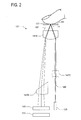
- Fig. 2 is a schematic of another embodiment of the data input device of the present invention.
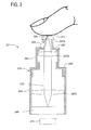
- Fig. 3 is a cross section of still another embodiment of the data input device of the present invention.
- Fig. 4 is a schematic of the data input device of the present invention adapted for use with a keyboard
- Fig. 5 is a schematic of the data input device of the present invention adapted for use with a laptop computer.
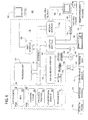
- Fig. 6 is a block diagram illustrating one example of a suitable computing system environment in which the invention may be implemented.
- the invention includes a data input device for use with a tracking surface that is optically rough, or in other words, has light-scattering properties, to track relative movement between the device and the tracking surface.
- FIG. 1 is a schematic of such a data input device and tracking surface of the present invention.
- the data input device generally indicated 21, includes a substantially coherent light source 25 (e.g., a laser) for projecting a substantially coherent light beam, generally indicated 29.
- the substantially coherent light beam projects onto a tracking surface 31 during operation of the device 21.
- the tracking surface 31 scatters the substantially coherent light beam 29 striking the tracking surface as a scattered light beam 33, as will be discussed in greater detail below.
- the substantially coherent light scattered from the tracking surface produces a speckle pattern S (e.g., Fig. 1A).
- speckle pattern S e.g., Fig. 1A
- paper, wood, metal, fabric, plastic and human skin each generally have sufficient surface variation to scatter a speckle pattern S.
- the substantially coherent light source 25 is modeled as a point source, such that a wavefront profile 35A of the substantially coherent light beam 29 is substantially curved.
- Wavefront profile 35 is defined herein as any constant phase profile passing through the substantially coherent light beam 29.
- An infinite number of such wavefront profiles 35 exist along the substantially coherent light beam 29, but typically such wavefront profiles are not planar.
- the wavefront profile 35A depicted in Fig. 1 is curved, demonstrating that the substantially coherent light leaving the substantially coherent light source 25 does not have a planar wavefront profile.
- the shortest path length from the substantially coherent light source 25 to any flat surface is along the normal line between the two, while all other non-normal, substantially coherent light arrive at the flat surface out-of-phase and at some later time, proportional to radial position.
- Optics may correct this out-of-phase condition, such that at least one wavefront profile is substantially planar. It is desirable to place such a planar wavefront profile at the plane P of the detector 49 so that the scattered substantially coherent light arrives at the detector substantially in-phase.
- a number of different types of optics are capable of altering the substantially coherent light beam in this manner, as would be readily understood by those skilled in the art.
- optics alter the shape of the wavefront profile as the light passes through the device 21.
- the substantially coherent light beam 29 first passes through a field stop 41 as it travels toward the tracking surface 31.
- This field stop 41 includes an opening 43 for defining the shape of the substantially coherent light beam 29 projected toward the tracking surface.
- This field stop 41 and substantially coherent light beam 29 combination is particularly useful if the substantially coherent light source 25 does not project a narrow beam, as may be the case with relatively inexpensive sources of substantially coherent light. Instead, the field stop 41 can readily define the width and direction of the projected substantially coherent light beam 29.
- the substantially coherent light source 25 is a vertical cavity surface emitting laser (VCSEL) having a small aperture size, such as 10 to 20 microns (0.39 to 0.79 mils (milliinches)).
- the wavefront profile 35 of the substantially coherent light beam 29 produced by such a VCSEL may be modeled as a spherical wave emanating from a point source.
- VCSEL vertical cavity surface emitting laser
- a greater or fewer number of field stops 41 for altering the shape of the substantially coherent light beam 29 may be utilized without departing from the scope of the claimed invention.
- no field stop 41 is needed.
- the device 21 further comprises multiple optics 47 for guiding the projected substantially coherent light beam toward the tracking surface 31 and the scattered light beam toward a detector 49 associated with the substantially coherent light source 25.
- the detector 49 is adapted to detect at least a portion of the substantially coherent light beam 29 scattered by the tracking surface 31 as the scattered light beam 33, the detected portion comprising the speckle pattern S.
- the detector 49 further defines a plane P for detecting the scattered light beam 33, as will be discussed in greater detail below.
- the two optics 47 are utilized to control the substantially coherent light beam 29 and the scattered light beam 33.
- the two optics 47 include a first optic 47A arranged between the tracking surface 31 and both the detector 49 and the substantially coherent light source 25, and a second optic 47B arranged between the detector and the first optic, as will be discussed in greater detail below.
- the first optic 47A comprises a first boundary 55 facing the substantially coherent light source 25 and the detector 49, and a second boundary 57 opposite the first boundary and configured to face the tracking surface 31.
- the first boundary 55 is convex, such that the substantially coherent light beam 29 converges slightly as it passes through the first boundary.
- the second boundary 57 is substantially flat, such that the substantially coherent light beam 29 neither converges nor diverges as it passes through the second boundary. (It is also contemplated that the second boundary 57 may have a curvature, without departing from the scope of the present invention.) But a retro-reflection 63 of the substantially coherent light beam 29 does reflect from the second boundary 57 and in the general direction of the detector 49. Because this retro-reflection 63 is not indicative of movement of the tracking surface 31 relative to the device 21, it is effectively noise, thereby degrading the signal-to-noise ratio of the signal, and therefore its detection by the detector 49 should be avoided.
- the tracking surface may be spaced from the second boundary 57 by a distance D sufficient to inhibit any substantial retro-reflection of the substantially coherent light beam 29 striking the first boundary 55 from striking the detector 49.
- the retro-reflection 63 is offset, or laterally sheared, from the scattered light beam 33, such that the optics 47 and detector 49 of the device 21 may be positioned to avoid detecting the retro-reflection.
- distance D increases, the offset between the retro-reflection 63 and the scattered light beam 33 also increases.
- the spaced-apart distance D is at least about 2 millimeters (mm) (0.08 inch). In another example, the spaced-apart distance is at least about 7 mm (0.3 inch).
- the optic may be an uncoated optic, which significantly reduces the cost of such an optic. It should be understood by those skilled in the art that coated optics may also be used without departing from the scope of the present invention. Utilizing such coated optics may reduce the need to separate the optic from the tracking surface, although some separation is likely required for protection of the optic from repeated contact with the tracking surface.
- An additional retro-reflection (not shown) of the substantially coherent light beam 29 reflects from the first boundary 55 in the general direction of the detector 49. However, because the first boundary 55 is spaced further from the tracking surface 31 than the second boundary 57, the retro-reflection is further offset, or laterally sheared, from the scattered light beam 33.
- the device 21 may further comprise a spacing medium 67 adjacent the second boundary 57 of the optic 47A adapted to maintain the spaced-apart distance between the second boundary and the tracking surface 31.
- the spacing medium 67 may be an air space maintained by a support surface 69 having an opening 71 therein and engageable with the tracking surface 31 for maintaining the appropriate spacing between the tracking surface and the optic 47A, while allowing the substantially coherent light beam 29 to strike the tracking surface.
- the tracking surface 31 is human skin, as depicted in Fig.
- the spacing medium 67 ensures the appropriate spacing for inhibiting the retro-reflection 63 from striking the detector 49, while facilitating accurate position determination of the tracking surface by positioning the user's finger at the appropriate position relative the first optic 47A.
- the substantially coherent light beam 29 passes through the air space of the spacing medium 67 and the opening 71 in the support surface 69 to project onto the tracking surface 31, here a fingertip of the user.
- the tracking surface 31 scatters the substantially coherent light beam 29, thereby creating the scattered light beam 33 noted above.
- the wavefront profile 35C of the scattered light beam 33 remains curved, such that direct detection of the scattered light beam, without further optical manipulation, would not provide a substantially stable speckle pattern S, as will be described in detail below.
- the spacing medium 67 is a transparent material, such as glass or plastic.
- the second optic 47B collects at least a portion of the scattered light beam and alters the wavefront profile 35D of the collected scattered light beam 33 so that after manipulation, the collected scattered light beam 33' has a substantially constant phase relative to the plane of the detector. This substantially constant phase of the wavefront profile 35D ensures that the detector 49 detects a substantially stable speckle pattern S from the collected scattered light beam 33'.
- the device 21 also comprises another field stop 41' associated with the second optic for limiting the ability of the retro-reflection to strike the second optic or the detector 49.
- the substantially coherent light source 25 and detector 49 may be arranged nearer one another, such that the second optic 47B may be a rotationally symmetric, rather than prismatic, as depicted in Fig. 1.
- the substantially coherent light source 25 and detector 49 may be arranged with a center-to-center spacing of about 2 mm (0.08 inch), such that the second optic 47B may be replaced with a piano convex optic.
- the device 21 further comprises a controller, or tracking engine, 73 responsive to the detector 49 for operating the device in a tracking mode by utilizing the detected speckle pattern S to track relative movement between the device and the tracking surface 31.
- the speckle pattern S is useful for tracking because as the substantially coherent light beam 29 and tracking surface move relative to one another, the spatial relationships of the speckle grains in the speckle pattern are maintained as the speckle image translates across the detector 49, enabling a strong correlation to a reference image, or previous speckle image, in the tracking engine.
- the stable speckle pattern S allows the tracking engine 73 to follow its path across the detector 49, thereby indicating relative movement between the device 21 and the tracking surface 31.
- Transient speckle grains are not suitable for tracking because they may disappear and reappear as the device 21 and tracking surface 31 move relative to one another, reducing the correlation strength relative to the reference image of the tracking engine 73.
- a substantially stable speckle pattern S is characterized by a substantial portion of stable speckle grains upon which relative movement of the device 21 and the tracking surface 31 may be tracked.
- Correlation and phase-based tracking engines 73 depend upon a sequence of stable images to correctly identify tracking motion. Degradation or distortion of tracking input images relative to a reference image severely impairs accurate functioning of correlation and phase-based tracking engines 73.
- a substantially stable speckle pattern S improves functioning of tracking engines 73 because it provides a reliable image by which relative movement of the device 21 and tracking surface 31 may be tracked.
- a speckle pattern S exhibiting speckle grains that are not substantially stable is characterized as boiling and is typically caused because the substantially coherent light beam 29 striking the tracking surface 31 has a changing phase profile over the extent of the beam, leading to substantial phase distortion.
- Techniques for minimizing speckle pattern S boiling will be discussed in greater detail below.
- Other types of tracking engines, beyond correlation tracking engines and phase-based tracking engines, are also contemplated as within the scope of the present invention.
- tracking relative movement between the device 21 and the tracking surface 31 using the scattered speckle pattern S offers several advantages.
- Third, utilizing a speckle pattern S as the tracking indicia eliminates the need for a patterned surface having a particular resolution, such as a patterned ball or a patterned mouse pad, as was practiced in the prior art.
- the third feature is particularly useful when the tracking surface 31 is human skin, as depicted in Fig. 1.
- the maximum resolution available from such a system is limited to about 500 dots per inch (dpi). This resolution limit is brought about due to the inherent size of fingerprint features, which are too large to provide precise tracking above about 500 dpi.
- a user utilizing a device having a resolution of 500 dpi would need to repeatedly translate and pick up the tracking finger (i.e., clutching) to move a cursor completely across a display, where each dot of resolution in a particular direction corresponds to a single pixel of the display in the same direction. For example, for a display having 1024 horizontal pixels and a finger width of 15 mm (0.59 inch), between three and four clutches would be required to move the cursor across the entire display.
- the response to relative movement of the tracking surface 31 and device 21 may be magnified by a factor, such as four, but such a magnification factor also induces a subsequent loss in precision, whereby only every fourth pixel on the display may be selected by the user.
- tracking based upon laser speckle rather than surface features of the tracking surface 31, dramatically increases the potential tracking resolution.
- a typical mechanical mouse tracks at approximately 500 dpi, such that about 51 mm (2.0 inches) of travel is required for traversing a 1024 pixel display, assuming one dot per pixel, or maximum precision.
- a single human finger is insufficiently wide to traverse a 1024 pixel display at 500 dpi resolution without clutching.
- the tracking resolution for movement between the tracking surface 31 and the device 21 increases in one example to at least about 1000 dpi, and in another example to at least about 2000 dpi, which is suitable for a finger tracking device.
- a user can translate a 1024 pixel display with less than two full passes of a single finger.
- a user can translate a 1024 pixel display within the width of a single finger.
- a device 21 having such a resolution is desirable because the user need not perform any clutching to transverse the entire width of the display. In other words, the user can manipulate the cursor about the entire display, without lifting the tracking finger from the device 21.
- finger tracking utilizing a substantially coherent light source 25 and a speckle pattern S provides several advantages over traditional surface feature tracking.
- a VCSEL substantially coherent light source 25
- a VCSEL has the distinct advantage drawing less than about 10 mW (13 ⁇ horsepower) of power, and having a maximum optical output power of 1 mW (1.3 ⁇ horsepower).
- VCSELs are relatively small in size, easing packaging considerations, and are relatively inexpensive to manufacture, easing cost considerations.
- maintaining the power of the laser at a relatively low level ensures that the laser does not present an eye hazard for the user.
- Other lasers and sources of substantially coherent light may also be utilized without departing from the scope of the claimed invention.
- the substantially coherent light source may project an infrared, substantially coherent light beam, which is beneficial because VCSELs may be readily manufactured at this wavelength and may be less expensive than visible sources.
- it may also project a substantially coherent light beam having a substantially unitary polarization, which may help generate a single speckle field and additional speckle pattern stability.
- multimode substantially coherent light sources e.g., a multimode VCSELs
- VCSELs which alternate polarization states between several modes and orthogonal directions
- the detector 49 of the device 21 detects the speckle pattern S scattered by the tracking surface 31 and images the detected speckle pattern. Any detector 49 capable of imaging the speckle pattern S may be utilized with the present embodiment. Such detectors 49 may include photodetectors, CCDs (charge-coupled devices), CMOS (complementary metal-oxide semiconductor) technology or other detector arrays.
- the detector 49 detects the dark and light pattern generated by the speckle pattern S and sends information corresponding to this detected speckle grain to the controller 73, which is responsive to the detector.
- the controller 73 then utilizes the speckle pattern S to track the relative movement between the device 21 and the tracking surface 31.
- Tracking engines 73 utilizing pattern detection to correlate a moving pattern as well as other tracking methods are well known in the art and will not be described in detail here. More importantly, tracking relative movement between the device 21 and the tracking surface 31 by detecting movement of the speckle pattern S is only feasible when the speckle pattern is substantially stable.
- a substantially stable speckle pattern S should produce speckle grains that are substantially stationary with respect to the tracking surface 31 and substantially constant in brightness, acting as tracking indicia on what may be an unmarked tracking surface.
- the detector 49 and controller 73 can work together to track the movement of such grains, thereby tracking relative movement between the device 21 and any optically rough tracking surface 31.
- One skilled in the art would readily understand how to utilize a detector 49 and a tracking engine 73 to utilize the movement of a substantially stable pattern S, here the substantially stable speckle grains, across the detector with relative movement between the device 21 and the tracking surface 31.
- the controller 73 is also responsive to the detector 49 for suspending tracking of relative movement between the device and the tracking surface when the detector detects an off-surface condition, such as due to speckle boiling, as described in co-pending U.S. Application No. 10/641,672 (noted above), commonly assigned to Microsoft Corporation. The details of such application are incorporated by reference herein.
- the device 121 comprises a substantially coherent light source 125 projecting a substantially coherent light beam 129 and a first optic 147A arranged between the tracking surface 31 and both a detector 149 and the substantially coherent light source 125, and a second optic 147B arranged between the detector and the first optic, generally as set forth above.
- the device 121 comprises a third optic 147C (such as a collimator) for further control over the wavefront profile of the substantially coherent light beam 129.
- the device 121 further comprises a spacing medium 167 for inhibiting retro-reflection from interfering with tracking and a controller 173 for tracking relative movement between the device 121 and a tracking surface 131, generally as set forth above.
- the device 221 comprises a substantially coherent light source 225 for projecting a substantially coherent light beam 229, a first optic 247A adapted for contact with a tracking surface 231 for scattering the substantially coherent light, second and third optics 247B,247C for guiding a scattered light beam 233 toward a detector 249, and a controller 273 associated with the detector for tracking relative movement between the device and the tracking surface, generally as set forth above.
- the substantially coherent light source 225 includes a collimating lens (not shown) for collimating the substantially coherent light beam 229 adjacent the substantially coherent light source (i.e., before the beam reaches the first optic 247A).
- the substantially coherent light source 225 may comprise a VCSEL (as generally described above) and an integral collimating lens, such as a 2 mm (0.08 inch) diameter, plano-convex lens sold as the OptoSigma Model No. 011-007 available from OptoSigma Corporation of Santa Ana, California.
- the second and third optics 247B,247C may be a bi-convex, aspherical lenses.
- the second optic 247B may be arranged at a distance from the first optic 247A equivalent to its focal length.
- the third optic 247C may be arranged at a distance from the detector 249 equivalent to its focal length.
- the second optic 247B and third optic 247C may be positioned for back-to-back, infinite focus with respect to one another. This arrangement positions the focal plane of the detector 249 at one focal length from the third optic 247C, which focuses the speckle image at infinity, thereby presenting a collimated input to the detector.
- This arrangement is beneficial for controlling the scattered light beam 233 to exhibit a wavefront profile at the detector 249 having a substantially constant phase, so that the detector may detect a substantially stable speckle pattern S.
- the device 221 also comprises a housing, generally indicated 279.
- the housing depicted is formed from several portions, including two cylindrical sections 283, a joint 285 connecting the cylindrical sections, and an upper housing 287 extending upward from the uppermost cylindrical section.
- the first optic 247A and the substantially coherent light source 225 mount on an upper end of the upper housing 287.
- the second optic 247B is received within the uppermost cylindrical section 283, while the third optic 247C is received within the lowermost cylindrical section.
- the detector 249 mounts within the lowermost cylindrical section 283, beneath the third optic 247C.
- the housing 279 receives the optics 247 and detector 249, and the housing may take any number of shapes without departing from the scope of the claimed invention.
- the devices of the present invention may be used as a data input devices for pointing with virtually any device or apparatus.
- Figs. 4 and 5 depict two examples where a data input device of the claimed invention would be particularly useful.
- Fig. 4 depicts a device of the present invention, generally indicated 321, integral with a keyboard 327, having a spacing medium 367 of the device also integral with the keyboard, such that as the user utilizes the keyboard, the user may also manipulate the device to alter the location of a pointer on a display associated with the keyboard.
- the spacing medium 367 may be positioned adjacent a home position of a typing finger of the keyboard 327 for ease of access to the spacing medium by a typing finger.
- FIG. 5 depicts a device of the present invention, generally indicated 421, integral with a laptop computer 437, having a spacing medium 467 of the device also integral with the laptop computer, such that as the user utilizes the laptop computer, the user may also manipulate the device to alter the location of a pointer on the display of the laptop computer.
- Such devices are also particularly useful in handheld devices, such as personal digital assistants, cellular phones, as well as any other electronic device where it is desirable to locate a data input device on the device itself, for interaction with a tracking surface comprising human skin, such as a fingertip.
- Fig. 6 shows one example of a general purpose computing device in the form of a computer 130.
- a computer such as the computer 130 is suitable for use in the other figures illustrated and described herein.
- Computer 130 has one or more processors or processing units 132 and a system memory 134.
- a system bus 136 couples various system components including the system memory 134 to the processors 132.
- the bus 136 represents one or more of any of several types of bus structures, including a memory bus or memory controller, a peripheral bus, an accelerated graphics port, and a processor or local bus using any of a variety of bus architectures.
- such architectures include Industry Standard Architecture (ISA) bus, Micro Channel Architecture (MCA) bus, Enhanced ISA (EISA) bus, Video Electronics Standards Association (VESA) local bus, and Peripheral Component Interconnect (PCI) bus also known as Mezzanine bus.
- ISA Industry Standard Architecture
- MCA Micro Channel Architecture
- EISA Enhanced ISA
- VESA Video Electronics Standards Association
- PCI Peripheral Component Interconnect
- the computer 130 typically has at least some form of computer readable media.
- Computer readable media which include both volatile and nonvolatile media, removable and non-removable media, may be any available medium that can be accessed by computer 130.
- Computer readable media comprise computer storage media and communication media.
- Computer storage media include volatile and nonvolatile, removable and non-removable media implemented in any method or technology for storage of information such as computer readable instructions, data structures, program modules or other data.
- computer storage media include RAM, ROM, EEPROM, flash memory or other memory technology, CD-ROM, digital versatile disks (DVD) or other optical disk storage, magnetic cassettes, magnetic tape, magnetic disk storage or other magnetic storage devices, or any other medium that can be used to store the desired information and that can be accessed by computer 130.
- Communication media typically embody computer readable instructions, data structures, program modules, or other data in a modulated data signal such as a carrier wave or other transport mechanism and include any information delivery media. Those skilled in the art are familiar with the modulated data signal, which has one or more of its characteristics set or changed in such a manner as to encode information in the signal.
- Wired media such as a wired network or direct-wired connection
- wireless media such as acoustic, RF, infrared, and other wireless media
- communication media such as acoustic, RF, infrared, and other wireless media
- the system memory 134 includes computer storage media in the form of removable and/or non-removable, volatile and/or nonvolatile memory.
- system memory 134 includes read only memory (ROM) 138 and random access memory (RAM) 140.
- ROM read only memory
- RAM random access memory
- BIOS basic input/output system
- RAM 140 typically contains data and/or program modules that are immediately accessible to and/or presently being operated on by processing unit 132.
- Fig. 6 illustrates operating system 144, application programs 146, other program modules 148, and program data 150.
- the computer 130 may also include other removable/non-removable, volatile/nonvolatile computer storage media.
- Fig. 6 illustrates a hard disk drive 154 that reads from or writes to non-removable, nonvolatile magnetic media.
- Fig. 6 also shows a magnetic disk drive 156 that reads from or writes to a removable, nonvolatile magnetic disk 158, and an optical disk drive 160 that reads from or writes to a removable, nonvolatile optical disk 162 such as a CD-ROM or other optical media.
- removable/non-removable, volatile/nonvolatile computer storage media that can be used in the exemplary operating environment include, but are not limited to, magnetic tape cassettes, flash memory cards, digital versatile disks, digital video tape, solid state RAM, solid state ROM, and the like.
- the hard disk drive 154, and magnetic disk drive 156 and optical disk drive 160 are typically connected to the system bus 136 by a non-volatile memory interface, such as interface 166.
- the drives or other mass storage devices and their associated computer storage media discussed above and illustrated in Fig. 6, provide storage of computer readable instructions, data structures, program modules and other data for the computer 130.
- hard disk drive 154 is illustrated as storing operating system 170, application programs 172, other program modules 174, and program data 176. Note that these components can either be the same as or different from operating system 144, application programs 146, other program modules 148, and program data 150. Operating system 170, application programs 172, other program modules 174, and program data 176 are given different numbers here to illustrate that, at a minimum, they are different copies.
- a user may enter commands and information into computer 130 through input devices or user interface selection devices such as a keyboard 180 and a pointing device 182 (e.g., a mouse, trackball, pen, or touch pad).
- Other input devices may include a microphone, joystick, game pad, camera, scanner, or the like.
- processing unit 132 through a user input interface 184 that is coupled to system bus 136, but may be connected by other interface and bus structures, such as a parallel port, game port, or a Universal Serial Bus (USB).
- a monitor 188 or other type of display device is also connected to system bus 136 via an interface, such as a video interface 190.
- computers often include other peripheral output devices (not shown) such as a printer and speakers, which may be connected through an output peripheral interface (not shown).
- the computer 130 may operate in a networked environment using logical connections to one or more remote computers, such as a remote computer 194.
- the remote computer 194 may be a personal computer, a server, a router, a network PC, a peer device or other common network node, and typically includes many or all of the elements described above relative to computer 130.
- the logical connections depicted in Fig. 6 include a local area network (LAN) 196 and a wide area network (WAN) 198, but may also include other networks.
- LAN 136 and/or WAN 138 can be a wired network, a wireless network, a combination thereof, and so on.
- Such networking environments are commonplace in offices, enterprise-wide computer networks, intranets, and global computer networks (e.g., the Internet).
- computer 130 When used in a local area networking environment, computer 130 is connected to the LAN 196 through a network interface or adapter 186. When used in a wide area networking environment, computer 130 typically includes a modem 178 or other means for establishing communications over the WAN 198, such as the Internet.
- the modem 178 which may be internal or external, is connected to system bus 136 via the user input interface 184, or other appropriate mechanism.
- program modules depicted relative to computer 130, or portions thereof may be stored in a remote memory storage device (not shown).
- Fig. 6 illustrates remote application programs 192 as residing on the memory device. It will be appreciated that the network connections shown are exemplary and other means of establishing a communications link between the computers may be used.
- the data processors of computer 130 are programmed by means of instructions stored at different times in the various computer-readable storage media of the computer.
- Programs and operating systems are typically distributed, for example, on floppy disks or CD-ROMs. From there, they are installed or loaded into the secondary memory of a computer. At execution, they are loaded at least partially into the computer's primary electronic memory.
- the invention described herein includes these and other various types of computer-readable storage media when such media contain instructions or programs for implementing the operations described below in conjunction with a microprocessor or other data processor.
- computing system environment is not intended to suggest any limitation as to the scope of use or functionality of the invention.
- computing system environment should not be interpreted as having any dependency or requirement relating to any one or combination of components illustrated in the exemplary operating environment.
- Examples of well known computing systems, environments, and/or configurations that may be suitable for use with the invention include, but are not limited to, personal computers, server computers, hand-held or laptop devices, multiprocessor systems, microprocessor-based systems, set top boxes, programmable consumer electronics, mobile telephones, network PCs, minicomputers, mainframe computers, distributed computing environments that include any of the above systems or devices, and the like.
Landscapes
- Engineering & Computer Science (AREA)
- General Engineering & Computer Science (AREA)
- Theoretical Computer Science (AREA)
- Human Computer Interaction (AREA)
- Physics & Mathematics (AREA)
- General Physics & Mathematics (AREA)
- Position Input By Displaying (AREA)
- Length Measuring Devices By Optical Means (AREA)
Applications Claiming Priority (2)
| Application Number | Priority Date | Filing Date | Title |
|---|---|---|---|
| US837052 | 1986-03-06 | ||
| US10/837,052 US7292232B2 (en) | 2004-04-30 | 2004-04-30 | Data input devices and methods for detecting movement of a tracking surface by a laser speckle pattern |
Publications (3)
| Publication Number | Publication Date |
|---|---|
| EP1591880A2 true EP1591880A2 (fr) | 2005-11-02 |
| EP1591880A3 EP1591880A3 (fr) | 2006-04-12 |
| EP1591880B1 EP1591880B1 (fr) | 2018-07-25 |
Family
ID=34939479
Family Applications (1)
| Application Number | Title | Priority Date | Filing Date |
|---|---|---|---|
| EP05103323.1A Expired - Lifetime EP1591880B1 (fr) | 2004-04-30 | 2005-04-25 | Dispositif et procédé d'entrée de données pour détécter le mouvement d'une surface de localisation en employant un motif de speckle |
Country Status (3)
| Country | Link |
|---|---|
| US (1) | US7292232B2 (fr) |
| EP (1) | EP1591880B1 (fr) |
| JP (1) | JP5236860B2 (fr) |
Cited By (4)
| Publication number | Priority date | Publication date | Assignee | Title |
|---|---|---|---|---|
| EP2073103A1 (fr) * | 2007-12-19 | 2009-06-24 | Research In Motion Limited | Mécanisme d'entrée pour dispositif de communication électronique portable |
| US8106885B2 (en) | 2007-12-19 | 2012-01-31 | Research In Motion Limited | Input mechanism for handheld electronic communication device |
| DE102011112568A1 (de) * | 2011-09-08 | 2013-03-14 | Daimler Ag | Bedienvorrichtung für ein Lenkrad eines Kraftfahrzeugs, Lenkrad für ein Kraftfahrzeug und Kraftfahrzeug |
| EP2596320A4 (fr) * | 2010-07-24 | 2015-08-26 | Focused Innovation Inc | Procédé et appareil d'imagerie |
Families Citing this family (41)
| Publication number | Priority date | Publication date | Assignee | Title |
|---|---|---|---|---|
| US7773070B2 (en) | 2004-05-21 | 2010-08-10 | Cypress Semiconductor Corporation | Optical positioning device using telecentric imaging |
| US20050275625A1 (en) * | 2004-06-15 | 2005-12-15 | Koenig Douglas W | Ergonomic computer input device having pistol-type grip |
| US7295324B2 (en) * | 2004-07-13 | 2007-11-13 | Mitutoyo Corporation | System and method for improving accuracy in a speckle-based image correlation displacement sensor |
| US7528824B2 (en) * | 2004-09-30 | 2009-05-05 | Microsoft Corporation | Keyboard or other input device using ranging for detection of control piece movement |
| EP1851678A2 (fr) * | 2005-02-08 | 2007-11-07 | Koninklijke Philips Electronics N.V. | Analyse de figure de speckle optique |
| US20060213997A1 (en) * | 2005-03-23 | 2006-09-28 | Microsoft Corporation | Method and apparatus for a cursor control device barcode reader |
| US7557795B2 (en) * | 2005-06-30 | 2009-07-07 | Microsoft Corporation | Input device using laser self-mixing velocimeter |
| US7543750B2 (en) * | 2005-11-08 | 2009-06-09 | Microsoft Corporation | Laser velocimetric image scanning |
| US7505033B2 (en) * | 2005-11-14 | 2009-03-17 | Microsoft Corporation | Speckle-based two-dimensional motion tracking |
| US20070109267A1 (en) * | 2005-11-14 | 2007-05-17 | Microsoft Corporation | Speckle-based two-dimensional motion tracking |
| US9182837B2 (en) * | 2005-11-28 | 2015-11-10 | Synaptics Incorporated | Methods and systems for implementing modal changes in a device in response to proximity and force indications |
| US7737948B2 (en) * | 2005-12-20 | 2010-06-15 | Cypress Semiconductor Corporation | Speckle navigation system |
| CN101496032B (zh) * | 2006-02-27 | 2011-08-17 | 普莱姆传感有限公司 | 使用斑纹解相关的距离映射的方法及设备 |
| US7675020B2 (en) * | 2006-08-28 | 2010-03-09 | Avago Technologies General Ip (Singapore) Pte. Ltd. | Input apparatus and methods having diffuse and specular tracking modes |
| US7969426B2 (en) * | 2006-10-31 | 2011-06-28 | Hewlett-Packard Development Company, L.P. | Light sensitive display interface for computing devices |
| US8089465B2 (en) * | 2006-11-16 | 2012-01-03 | Microsoft Corporation | Speckle interference laser tracking |
| US8202268B1 (en) | 2007-03-18 | 2012-06-19 | Lockheed Martin Corporation | Method and multiple-mode device for high-power short-pulse laser ablation and CW cauterization of bodily tissues |
| US20080231596A1 (en) * | 2007-03-19 | 2008-09-25 | Yung-Lung Liu | Key shaped pointing device |
| EP2207595A4 (fr) * | 2007-10-19 | 2012-10-24 | Lockheed Corp | Système et procédé de conditionnement de tissu animal par rayon laser |
| US8169420B2 (en) * | 2008-02-05 | 2012-05-01 | Avago Technologies Ecbu Ip (Singapore) Pte. Ltd. | Reporting optical tracking data based on integrated resolution switching and surface detection |
| US20100060567A1 (en) * | 2008-09-05 | 2010-03-11 | Microsoft Corporation | Controlling device operation relative to a surface |
| US8093545B2 (en) * | 2008-09-26 | 2012-01-10 | Avago Technologies Ecbu Ip (Singapore) Pte. Ltd. | Lensless user input device with optical interference based on diffraction with a small aperture |
| US8237684B2 (en) * | 2008-09-26 | 2012-08-07 | Avago Technologies Ecbu Ip (Singapore) Pte. Ltd. | User input device with planar light guide illumination plate |
| US8541727B1 (en) | 2008-09-30 | 2013-09-24 | Cypress Semiconductor Corporation | Signal monitoring and control system for an optical navigation sensor |
| CN102246124B (zh) | 2008-12-08 | 2015-01-28 | 皇家飞利浦电子股份有限公司 | 跟踪球模块 |
| US8711096B1 (en) | 2009-03-27 | 2014-04-29 | Cypress Semiconductor Corporation | Dual protocol input device |
| US10691261B2 (en) * | 2011-01-19 | 2020-06-23 | Pixart Imaging Inc. | Non-planar reflective folded optics |
| US8534876B2 (en) | 2011-02-10 | 2013-09-17 | Avago Technologies General Ip (Singapore) Pte. Ltd. | Ultra-low profile optical finger navigation illumination system through segmentation |
| US20120235955A1 (en) * | 2011-03-17 | 2012-09-20 | Sae Magnetics (H.K.) Ltd. | Optical navigation module |
| US20120242620A1 (en) * | 2011-03-22 | 2012-09-27 | Research In Motion Limited | Combined optical navigation and button |
| US9272221B2 (en) * | 2013-03-06 | 2016-03-01 | Steelseries Aps | Method and apparatus for configuring an accessory device |
| US9208566B2 (en) | 2013-08-09 | 2015-12-08 | Microsoft Technology Licensing, Llc | Speckle sensing for motion tracking |
| US10488518B2 (en) * | 2015-06-03 | 2019-11-26 | Ams Sensors Singapore Pte. Ltd. | Optoelectronic module operable for distance measurements |
| US9934418B2 (en) * | 2015-12-03 | 2018-04-03 | Synaptics Incorporated | Display integrated optical fingerprint sensor with angle limiting reflector |
| US10176355B2 (en) | 2015-12-03 | 2019-01-08 | Synaptics Incorporated | Optical sensor for integration in a display |
| US10169630B2 (en) | 2015-12-03 | 2019-01-01 | Synaptics Incorporated | Optical sensor for integration over a display backplane |
| US10152798B2 (en) * | 2017-04-10 | 2018-12-11 | Wisconsin Alumni Research Foundation | Systems, methods and, media for determining object motion in three dimensions using speckle images |
| AU2018257776A1 (en) * | 2017-04-24 | 2019-10-31 | Magic Leap, Inc. | Tracking optical flow of backscattered laser speckle patterns |
| TW201915818A (zh) * | 2017-10-05 | 2019-04-16 | 香港商印芯科技股份有限公司 | 光學識別模組 |
| IL294563B1 (en) | 2020-01-14 | 2026-04-01 | Pxe Computational Imaging Ltd | System and method for optical imaging and measurement of objects |
| CN114442851B (zh) * | 2022-01-28 | 2024-11-22 | 深圳Tcl新技术有限公司 | 激光处理方法、装置、存储介质、显示设备及激光设备 |
Family Cites Families (39)
| Publication number | Priority date | Publication date | Assignee | Title |
|---|---|---|---|---|
| US4364035A (en) | 1981-05-18 | 1982-12-14 | Kirsch Steven T | Electro-optical mouse |
| JPH0638224B2 (ja) * | 1984-09-27 | 1994-05-18 | ゼロツクス コーポレーシヨン | 光学式トランスレータ装置 |
| US4794384A (en) | 1984-09-27 | 1988-12-27 | Xerox Corporation | Optical translator device |
| US4719455A (en) | 1986-01-24 | 1988-01-12 | Louis William M | Integrating pointing device |
| JPS63317775A (ja) | 1987-06-19 | 1988-12-26 | Omron Tateisi Electronics Co | 長さ・速度測定装置 |
| US5274361A (en) | 1991-08-15 | 1993-12-28 | The United States Of America As Represented By The Secretary Of The Navy | Laser optical mouse |
| WO1993015098A1 (fr) * | 1992-01-31 | 1993-08-05 | Nippon Shinyaku Co., Ltd. | Derive d'une chaine de sucre du type lewis |
| US6031218A (en) | 1992-10-05 | 2000-02-29 | Logitech, Inc. | System and method for generating band-limited quasi-sinusoidal signals |
| US5729009A (en) | 1992-10-05 | 1998-03-17 | Logitech, Inc. | Method for generating quasi-sinusoidal signals |
| US5907152A (en) | 1992-10-05 | 1999-05-25 | Logitech, Inc. | Pointing device utilizing a photodetector array |
| GB2272763B (en) | 1992-11-14 | 1996-04-24 | Univ Sheffield | Device and method for determining movement |
| WO1994011845A1 (fr) | 1992-11-14 | 1994-05-26 | University Of Sheffield | Dispositif et procede de determination du deplacement d'une surface |
| US5712658A (en) | 1993-12-28 | 1998-01-27 | Hitachi, Ltd. | Information presentation apparatus and information display apparatus |
| US5489900A (en) | 1994-06-03 | 1996-02-06 | International Business Machines Corporation | Force sensitive transducer for use in a computer keyboard |
| US5428369A (en) | 1994-06-07 | 1995-06-27 | Kensington Microware Limited | Computer pointing device |
| US5694123A (en) | 1994-09-15 | 1997-12-02 | International Business Machines Corporation | Keyboard with integrated pointing device and click buttons with lock down for drag operation in a computer system with a graphical user interface |
| JP3270643B2 (ja) | 1994-12-22 | 2002-04-02 | キヤノン株式会社 | 指示位置検出方法及び装置 |
| US5578813A (en) | 1995-03-02 | 1996-11-26 | Allen; Ross R. | Freehand image scanning device which compensates for non-linear movement |
| GB9608770D0 (en) | 1996-04-27 | 1996-07-03 | Philips Electronics Nv | Projection display system |
| AU2940497A (en) | 1996-05-14 | 1997-12-05 | Michel Sayag | Method and apparatus for generating a control signal |
| EP0960369B1 (fr) | 1997-02-12 | 2001-07-04 | Kanitech A/S | Organe d'entree destine a un ordinateur |
| US5941783A (en) * | 1997-03-14 | 1999-08-24 | Schneider; James T. | Method of designating a player's team position |
| US5914783A (en) | 1997-03-24 | 1999-06-22 | Mistubishi Electric Information Technology Center America, Inc. | Method and apparatus for detecting the location of a light source |
| US6256016B1 (en) | 1997-06-05 | 2001-07-03 | Logitech, Inc. | Optical detection system, device, and method utilizing optical matching |
| US6448977B1 (en) | 1997-11-14 | 2002-09-10 | Immersion Corporation | Textures and other spatial sensations for a relative haptic interface device |
| US6424407B1 (en) | 1998-03-09 | 2002-07-23 | Otm Technologies Ltd. | Optical translation measurement |
| AU6633798A (en) | 1998-03-09 | 1999-09-27 | Gou Lite Ltd. | Optical translation measurement |
| US6057540A (en) * | 1998-04-30 | 2000-05-02 | Hewlett-Packard Co | Mouseless optical and position translation type screen pointer control for a computer system |
| US6531692B1 (en) | 1999-03-22 | 2003-03-11 | Microsoft Corporation | Optical coupling assembly for image sensing operator input device |
| US6455840B1 (en) | 1999-10-28 | 2002-09-24 | Hewlett-Packard Company | Predictive and pulsed illumination of a surface in a micro-texture navigation technique |
| US6256015B1 (en) * | 1999-12-29 | 2001-07-03 | Allan Adler | Computer mouse cover |
| JP2001330162A (ja) | 2000-05-23 | 2001-11-30 | Hitachi Constr Mach Co Ltd | アンロード弁 |
| US6642506B1 (en) | 2000-06-01 | 2003-11-04 | Mitutoyo Corporation | Speckle-image-based optical position transducer having improved mounting and directional sensitivities |
| WO2002037410A1 (fr) * | 2000-11-06 | 2002-05-10 | Koninklijke Philips Electronics N.V. | Procede de mesure du mouvement d'un dispositif de saisie |
| JP2004516542A (ja) * | 2000-12-15 | 2004-06-03 | フィンガー システム インク. | ペン型光マウス装置及びペン型光マウス装置の制御方法 |
| US7002549B2 (en) | 2001-01-18 | 2006-02-21 | Mccahon Stephen William | Optically based machine input control device |
| US20040061680A1 (en) | 2002-07-10 | 2004-04-01 | John Taboada | Method and apparatus for computer control |
| US7825895B2 (en) * | 2002-12-20 | 2010-11-02 | Itac Systems, Inc. | Cursor control device |
| US7227531B2 (en) | 2003-08-15 | 2007-06-05 | Microsoft Corporation | Data input device for tracking and detecting lift-off from a tracking surface by a reflected laser speckle pattern |
-
2004
- 2004-04-30 US US10/837,052 patent/US7292232B2/en not_active Expired - Fee Related
-
2005
- 2005-04-21 JP JP2005123817A patent/JP5236860B2/ja not_active Expired - Lifetime
- 2005-04-25 EP EP05103323.1A patent/EP1591880B1/fr not_active Expired - Lifetime
Cited By (5)
| Publication number | Priority date | Publication date | Assignee | Title |
|---|---|---|---|---|
| EP2073103A1 (fr) * | 2007-12-19 | 2009-06-24 | Research In Motion Limited | Mécanisme d'entrée pour dispositif de communication électronique portable |
| US8106885B2 (en) | 2007-12-19 | 2012-01-31 | Research In Motion Limited | Input mechanism for handheld electronic communication device |
| EP2596320A4 (fr) * | 2010-07-24 | 2015-08-26 | Focused Innovation Inc | Procédé et appareil d'imagerie |
| DE102011112568A1 (de) * | 2011-09-08 | 2013-03-14 | Daimler Ag | Bedienvorrichtung für ein Lenkrad eines Kraftfahrzeugs, Lenkrad für ein Kraftfahrzeug und Kraftfahrzeug |
| DE102011112568B4 (de) * | 2011-09-08 | 2015-11-19 | Daimler Ag | Bedienvorrichtung für ein Lenkrad eines Kraftfahrzeugs, Lenkrad für ein Kraftfahrzeug und Kraftfahrzeug |
Also Published As
| Publication number | Publication date |
|---|---|
| US7292232B2 (en) | 2007-11-06 |
| JP2005322226A (ja) | 2005-11-17 |
| JP5236860B2 (ja) | 2013-07-17 |
| US20050243055A1 (en) | 2005-11-03 |
| EP1591880B1 (fr) | 2018-07-25 |
| EP1591880A3 (fr) | 2006-04-12 |
Similar Documents
| Publication | Publication Date | Title |
|---|---|---|
| US7292232B2 (en) | Data input devices and methods for detecting movement of a tracking surface by a laser speckle pattern | |
| US7227531B2 (en) | Data input device for tracking and detecting lift-off from a tracking surface by a reflected laser speckle pattern | |
| US7161582B2 (en) | Data input device for tracking and detecting lift-off from a tracking surface by a reflected laser speckle pattern | |
| US7221356B2 (en) | Data input device and method for detecting an off-surface condition by a laser speckle size characteristic | |
| CN1910647B (zh) | 位置确定与运动追踪的方法及其系统 | |
| US9857892B2 (en) | Optical sensing mechanisms for input devices | |
| US7324086B2 (en) | Data input device and method for detecting lift-off from a tracking surface by laser doppler self-mixing effects | |
| US7126586B2 (en) | Data input devices and methods for detecting movement of a tracking surface by detecting laser doppler self-mixing effects of a frequency modulated laser light beam | |
| JP3837357B2 (ja) | コンピュータ用電子ペンデータ入力装置及び座標測定方法 | |
| JP4392377B2 (ja) | デバイスと表面との間の距離を測定する光学デバイス | |
| CN1928801B (zh) | 利用激光散斑的位置检测系统 | |
| KR100590375B1 (ko) | 핸드 헬드 입력 장치 및 호스트 프로세서 | |
| EP1512989B1 (fr) | Méthode et système pour la poursuite optique de cible utilisant une technique de triangulation | |
| US8345003B1 (en) | Optical positioning device using telecentric imaging | |
| US20050083303A1 (en) | Tracking motion using an interference pattern | |
| US20050156874A1 (en) | Data input device and method for detecting life-off from a tracking surface by laser doppler self-mixing effects | |
| KR20030062032A (ko) | 디지털 펜 장치 | |
| US7199791B2 (en) | Pen mouse | |
| JPWO2014076993A1 (ja) | インターフェース装置及び入力受付方法 | |
| EP2469378A2 (fr) | Système de saisie d'éléments graphiques | |
| US20060125792A1 (en) | Input device adapted for a variety of surfaces of different reflective natures | |
| CN201667061U (zh) | 笔型光学输入装置 | |
| US20070077900A1 (en) | Chirped grating finger navigation | |
| US20070241262A1 (en) | Optical sensing unit for an optical input device | |
| US7242466B2 (en) | Remote pointing system, device, and methods for identifying absolute position and relative movement on an encoded surface by remote optical method |
Legal Events
| Date | Code | Title | Description |
|---|---|---|---|
| PUAI | Public reference made under article 153(3) epc to a published international application that has entered the european phase |
Free format text: ORIGINAL CODE: 0009012 |
|
| AK | Designated contracting states |
Kind code of ref document: A2 Designated state(s): AT BE BG CH CY CZ DE DK EE ES FI FR GB GR HU IE IS IT LI LT LU MC NL PL PT RO SE SI SK TR |
|
| AX | Request for extension of the european patent |
Extension state: AL BA HR LV MK YU |
|
| PUAL | Search report despatched |
Free format text: ORIGINAL CODE: 0009013 |
|
| AK | Designated contracting states |
Kind code of ref document: A3 Designated state(s): AT BE BG CH CY CZ DE DK EE ES FI FR GB GR HU IE IS IT LI LT LU MC NL PL PT RO SE SI SK TR |
|
| AX | Request for extension of the european patent |
Extension state: AL BA HR LV MK YU |
|
| 17P | Request for examination filed |
Effective date: 20061009 |
|
| AKX | Designation fees paid |
Designated state(s): AT BE BG CH CY CZ DE DK EE ES FI FR GB GR HU IE IS IT LI LT LU MC NL PL PT RO SE SI SK TR |
|
| RAP1 | Party data changed (applicant data changed or rights of an application transferred) |
Owner name: MICROSOFT TECHNOLOGY LICENSING, LLC |
|
| 17Q | First examination report despatched |
Effective date: 20151015 |
|
| STAA | Information on the status of an ep patent application or granted ep patent |
Free format text: STATUS: EXAMINATION IS IN PROGRESS |
|
| REG | Reference to a national code |
Ref country code: DE Ref legal event code: R079 Ref document number: 602005054306 Country of ref document: DE Free format text: PREVIOUS MAIN CLASS: G06F0003033000 Ipc: G06F0003042000 |
|
| GRAP | Despatch of communication of intention to grant a patent |
Free format text: ORIGINAL CODE: EPIDOSNIGR1 |
|
| STAA | Information on the status of an ep patent application or granted ep patent |
Free format text: STATUS: GRANT OF PATENT IS INTENDED |
|
| RIC1 | Information provided on ipc code assigned before grant |
Ipc: G06F 3/042 20060101AFI20180130BHEP |
|
| INTG | Intention to grant announced |
Effective date: 20180222 |
|
| GRAS | Grant fee paid |
Free format text: ORIGINAL CODE: EPIDOSNIGR3 |
|
| GRAA | (expected) grant |
Free format text: ORIGINAL CODE: 0009210 |
|
| STAA | Information on the status of an ep patent application or granted ep patent |
Free format text: STATUS: THE PATENT HAS BEEN GRANTED |
|
| RIN1 | Information on inventor provided before grant (corrected) |
Inventor name: RANTA, CRAIG STEVEN Inventor name: LUTIAN, JOHN MICHAEL |
|
| AK | Designated contracting states |
Kind code of ref document: B1 Designated state(s): AT BE BG CH CY CZ DE DK EE ES FI FR GB GR HU IE IS IT LI LT LU MC NL PL PT RO SE SI SK TR |
|
| REG | Reference to a national code |
Ref country code: GB Ref legal event code: FG4D |
|
| REG | Reference to a national code |
Ref country code: CH Ref legal event code: EP |
|
| REG | Reference to a national code |
Ref country code: AT Ref legal event code: REF Ref document number: 1022457 Country of ref document: AT Kind code of ref document: T Effective date: 20180815 |
|
| REG | Reference to a national code |
Ref country code: DE Ref legal event code: R096 Ref document number: 602005054306 Country of ref document: DE |
|
| REG | Reference to a national code |
Ref country code: IE Ref legal event code: FG4D |
|
| REG | Reference to a national code |
Ref country code: NL Ref legal event code: FP |
|
| REG | Reference to a national code |
Ref country code: LT Ref legal event code: MG4D |
|
| REG | Reference to a national code |
Ref country code: AT Ref legal event code: MK05 Ref document number: 1022457 Country of ref document: AT Kind code of ref document: T Effective date: 20180725 |
|
| PG25 | Lapsed in a contracting state [announced via postgrant information from national office to epo] |
Ref country code: SE Free format text: LAPSE BECAUSE OF FAILURE TO SUBMIT A TRANSLATION OF THE DESCRIPTION OR TO PAY THE FEE WITHIN THE PRESCRIBED TIME-LIMIT Effective date: 20180725 Ref country code: GR Free format text: LAPSE BECAUSE OF FAILURE TO SUBMIT A TRANSLATION OF THE DESCRIPTION OR TO PAY THE FEE WITHIN THE PRESCRIBED TIME-LIMIT Effective date: 20181026 Ref country code: LT Free format text: LAPSE BECAUSE OF FAILURE TO SUBMIT A TRANSLATION OF THE DESCRIPTION OR TO PAY THE FEE WITHIN THE PRESCRIBED TIME-LIMIT Effective date: 20180725 Ref country code: BG Free format text: LAPSE BECAUSE OF FAILURE TO SUBMIT A TRANSLATION OF THE DESCRIPTION OR TO PAY THE FEE WITHIN THE PRESCRIBED TIME-LIMIT Effective date: 20181025 Ref country code: IS Free format text: LAPSE BECAUSE OF FAILURE TO SUBMIT A TRANSLATION OF THE DESCRIPTION OR TO PAY THE FEE WITHIN THE PRESCRIBED TIME-LIMIT Effective date: 20181125 Ref country code: AT Free format text: LAPSE BECAUSE OF FAILURE TO SUBMIT A TRANSLATION OF THE DESCRIPTION OR TO PAY THE FEE WITHIN THE PRESCRIBED TIME-LIMIT Effective date: 20180725 Ref country code: FI Free format text: LAPSE BECAUSE OF FAILURE TO SUBMIT A TRANSLATION OF THE DESCRIPTION OR TO PAY THE FEE WITHIN THE PRESCRIBED TIME-LIMIT Effective date: 20180725 Ref country code: PL Free format text: LAPSE BECAUSE OF FAILURE TO SUBMIT A TRANSLATION OF THE DESCRIPTION OR TO PAY THE FEE WITHIN THE PRESCRIBED TIME-LIMIT Effective date: 20180725 |
|
| REG | Reference to a national code |
Ref country code: CH Ref legal event code: PK Free format text: BERICHTIGUNGEN |
|
| RIC2 | Information provided on ipc code assigned after grant |
Ipc: G06F 3/042 20060101AFI20180130BHEP |
|
| PG25 | Lapsed in a contracting state [announced via postgrant information from national office to epo] |
Ref country code: ES Free format text: LAPSE BECAUSE OF FAILURE TO SUBMIT A TRANSLATION OF THE DESCRIPTION OR TO PAY THE FEE WITHIN THE PRESCRIBED TIME-LIMIT Effective date: 20180725 |
|
| REG | Reference to a national code |
Ref country code: DE Ref legal event code: R097 Ref document number: 602005054306 Country of ref document: DE |
|
| PG25 | Lapsed in a contracting state [announced via postgrant information from national office to epo] |
Ref country code: RO Free format text: LAPSE BECAUSE OF FAILURE TO SUBMIT A TRANSLATION OF THE DESCRIPTION OR TO PAY THE FEE WITHIN THE PRESCRIBED TIME-LIMIT Effective date: 20180725 Ref country code: IT Free format text: LAPSE BECAUSE OF FAILURE TO SUBMIT A TRANSLATION OF THE DESCRIPTION OR TO PAY THE FEE WITHIN THE PRESCRIBED TIME-LIMIT Effective date: 20180725 Ref country code: CZ Free format text: LAPSE BECAUSE OF FAILURE TO SUBMIT A TRANSLATION OF THE DESCRIPTION OR TO PAY THE FEE WITHIN THE PRESCRIBED TIME-LIMIT Effective date: 20180725 Ref country code: EE Free format text: LAPSE BECAUSE OF FAILURE TO SUBMIT A TRANSLATION OF THE DESCRIPTION OR TO PAY THE FEE WITHIN THE PRESCRIBED TIME-LIMIT Effective date: 20180725 |
|
| PGFP | Annual fee paid to national office [announced via postgrant information from national office to epo] |
Ref country code: FR Payment date: 20190313 Year of fee payment: 15 |
|
| PG25 | Lapsed in a contracting state [announced via postgrant information from national office to epo] |
Ref country code: DK Free format text: LAPSE BECAUSE OF FAILURE TO SUBMIT A TRANSLATION OF THE DESCRIPTION OR TO PAY THE FEE WITHIN THE PRESCRIBED TIME-LIMIT Effective date: 20180725 Ref country code: SK Free format text: LAPSE BECAUSE OF FAILURE TO SUBMIT A TRANSLATION OF THE DESCRIPTION OR TO PAY THE FEE WITHIN THE PRESCRIBED TIME-LIMIT Effective date: 20180725 |
|
| PLBE | No opposition filed within time limit |
Free format text: ORIGINAL CODE: 0009261 |
|
| STAA | Information on the status of an ep patent application or granted ep patent |
Free format text: STATUS: NO OPPOSITION FILED WITHIN TIME LIMIT |
|
| 26N | No opposition filed |
Effective date: 20190426 |
|
| PG25 | Lapsed in a contracting state [announced via postgrant information from national office to epo] |
Ref country code: SI Free format text: LAPSE BECAUSE OF FAILURE TO SUBMIT A TRANSLATION OF THE DESCRIPTION OR TO PAY THE FEE WITHIN THE PRESCRIBED TIME-LIMIT Effective date: 20180725 |
|
| REG | Reference to a national code |
Ref country code: DE Ref legal event code: R119 Ref document number: 602005054306 Country of ref document: DE |
|
| REG | Reference to a national code |
Ref country code: CH Ref legal event code: PL |
|
| REG | Reference to a national code |
Ref country code: NL Ref legal event code: MM Effective date: 20190501 |
|
| REG | Reference to a national code |
Ref country code: BE Ref legal event code: MM Effective date: 20190430 |
|
| GBPC | Gb: european patent ceased through non-payment of renewal fee |
Effective date: 20190425 |
|
| PG25 | Lapsed in a contracting state [announced via postgrant information from national office to epo] |
Ref country code: MC Free format text: LAPSE BECAUSE OF FAILURE TO SUBMIT A TRANSLATION OF THE DESCRIPTION OR TO PAY THE FEE WITHIN THE PRESCRIBED TIME-LIMIT Effective date: 20180725 Ref country code: LU Free format text: LAPSE BECAUSE OF NON-PAYMENT OF DUE FEES Effective date: 20190425 |
|
| PG25 | Lapsed in a contracting state [announced via postgrant information from national office to epo] |
Ref country code: NL Free format text: LAPSE BECAUSE OF NON-PAYMENT OF DUE FEES Effective date: 20190501 Ref country code: LI Free format text: LAPSE BECAUSE OF NON-PAYMENT OF DUE FEES Effective date: 20190430 Ref country code: CH Free format text: LAPSE BECAUSE OF NON-PAYMENT OF DUE FEES Effective date: 20190430 Ref country code: GB Free format text: LAPSE BECAUSE OF NON-PAYMENT OF DUE FEES Effective date: 20190425 Ref country code: DE Free format text: LAPSE BECAUSE OF NON-PAYMENT OF DUE FEES Effective date: 20191101 |
|
| PG25 | Lapsed in a contracting state [announced via postgrant information from national office to epo] |
Ref country code: BE Free format text: LAPSE BECAUSE OF NON-PAYMENT OF DUE FEES Effective date: 20190430 |
|
| PG25 | Lapsed in a contracting state [announced via postgrant information from national office to epo] |
Ref country code: TR Free format text: LAPSE BECAUSE OF FAILURE TO SUBMIT A TRANSLATION OF THE DESCRIPTION OR TO PAY THE FEE WITHIN THE PRESCRIBED TIME-LIMIT Effective date: 20180725 |
|
| PG25 | Lapsed in a contracting state [announced via postgrant information from national office to epo] |
Ref country code: IE Free format text: LAPSE BECAUSE OF NON-PAYMENT OF DUE FEES Effective date: 20190425 |
|
| PG25 | Lapsed in a contracting state [announced via postgrant information from national office to epo] |
Ref country code: PT Free format text: LAPSE BECAUSE OF FAILURE TO SUBMIT A TRANSLATION OF THE DESCRIPTION OR TO PAY THE FEE WITHIN THE PRESCRIBED TIME-LIMIT Effective date: 20181125 |
|
| PG25 | Lapsed in a contracting state [announced via postgrant information from national office to epo] |
Ref country code: FR Free format text: LAPSE BECAUSE OF NON-PAYMENT OF DUE FEES Effective date: 20200430 |
|
| PG25 | Lapsed in a contracting state [announced via postgrant information from national office to epo] |
Ref country code: CY Free format text: LAPSE BECAUSE OF FAILURE TO SUBMIT A TRANSLATION OF THE DESCRIPTION OR TO PAY THE FEE WITHIN THE PRESCRIBED TIME-LIMIT Effective date: 20180725 |
|
| PG25 | Lapsed in a contracting state [announced via postgrant information from national office to epo] |
Ref country code: HU Free format text: LAPSE BECAUSE OF FAILURE TO SUBMIT A TRANSLATION OF THE DESCRIPTION OR TO PAY THE FEE WITHIN THE PRESCRIBED TIME-LIMIT; INVALID AB INITIO Effective date: 20050425 |