EP1591892A2 - Gestion d'un réseau pour la présentation de vidéo - Google Patents
Gestion d'un réseau pour la présentation de vidéo Download PDFInfo
- Publication number
- EP1591892A2 EP1591892A2 EP05103623A EP05103623A EP1591892A2 EP 1591892 A2 EP1591892 A2 EP 1591892A2 EP 05103623 A EP05103623 A EP 05103623A EP 05103623 A EP05103623 A EP 05103623A EP 1591892 A2 EP1591892 A2 EP 1591892A2
- Authority
- EP
- European Patent Office
- Prior art keywords
- video
- configuration
- presenting network
- computer
- functional
- Prior art date
- Legal status (The legal status is an assumption and is not a legal conclusion. Google has not performed a legal analysis and makes no representation as to the accuracy of the status listed.)
- Withdrawn
Links
Images








Classifications
-
- G—PHYSICS
- G06—COMPUTING OR CALCULATING; COUNTING
- G06F—ELECTRIC DIGITAL DATA PROCESSING
- G06F17/00—Digital computing or data processing equipment or methods, specially adapted for specific functions
-
- H—ELECTRICITY
- H04—ELECTRIC COMMUNICATION TECHNIQUE
- H04N—PICTORIAL COMMUNICATION, e.g. TELEVISION
- H04N21/00—Selective content distribution, e.g. interactive television or video on demand [VOD]
- H04N21/40—Client devices specifically adapted for the reception of or interaction with content, e.g. set-top-box [STB]; Operations thereof
- H04N21/41—Structure of client; Structure of client peripherals
- H04N21/4104—Peripherals receiving signals from specially adapted client devices
- H04N21/4122—Peripherals receiving signals from specially adapted client devices additional display device, e.g. video projector
-
- G—PHYSICS
- G06—COMPUTING OR CALCULATING; COUNTING
- G06F—ELECTRIC DIGITAL DATA PROCESSING
- G06F15/00—Digital computers in general; Data processing equipment in general
- G06F15/16—Combinations of two or more digital computers each having at least an arithmetic unit, a program unit and a register, e.g. for a simultaneous processing of several programs
-
- H—ELECTRICITY
- H04—ELECTRIC COMMUNICATION TECHNIQUE
- H04L—TRANSMISSION OF DIGITAL INFORMATION, e.g. TELEGRAPHIC COMMUNICATION
- H04L12/00—Data switching networks
- H04L12/28—Data switching networks characterised by path configuration, e.g. LAN [Local Area Networks] or WAN [Wide Area Networks]
- H04L12/2803—Home automation networks
- H04L12/2807—Exchanging configuration information on appliance services in a home automation network
-
- H—ELECTRICITY
- H04—ELECTRIC COMMUNICATION TECHNIQUE
- H04L—TRANSMISSION OF DIGITAL INFORMATION, e.g. TELEGRAPHIC COMMUNICATION
- H04L12/00—Data switching networks
- H04L12/28—Data switching networks characterised by path configuration, e.g. LAN [Local Area Networks] or WAN [Wide Area Networks]
- H04L12/2803—Home automation networks
- H04L12/2838—Distribution of signals within a home automation network, e.g. involving splitting/multiplexing signals to/from different paths
Definitions
- the technical field relates to configuration of video display adapters (e.g., computer video cards).
- Computer systems using multiple monitors are becoming widespread. For example, it is now common for a computer to drive both an LCD panel and a projector device. Further, computer users now routinely watch video presentations (e.g., DVDs) using their computer. In such a case, the computer may be driving both a conventional monitor and a television.
- video presentations e.g., DVDs
- video adapter hardware manufacturers now include multiple outputs on video adapters. In this way, a user can more easily use a computer to drive desired devices without having to switch cables for a single output and reconfigure the output.
- multi-monitor video adapters have a variety of functionality, available configurations are typically limited. Accordingly, there exists a need to improve functionality related to configuring multi-monitor computer systems.
- Configuring a video presenting network having plural outputs can be challenging, due to the sheer number of possible configurations and configuration interdependencies among resources.
- a variety of technologies described herein can be used to configure resources of a video presenting network having plural outputs.
- provisional configuration can be supported. Configuration of inputs can be performed separately from configuration of outputs. Interdependencies between network resources can be considered to restrict provided options to those co-functional with a provisional configuration.
- a client can use a set of functions provided by a service to traverse the configuration solution space. Traversal through possible configuration solutions can include backtracking. For example, backtracking can be used when a selected configuration option invalidates another desired configuration option.
- Provisional configuration functionality can support a transactional configuration approach, and resources can be separately configured. An enumeration function can provide only those options co-functional with a provisional configuration, based on interdependencies between network resources. Validity of enumerated options can be guaranteed after pinning.
- the functions can be grouped into an interface that includes calls for enumerating configurations (e.g., those configurations that are co-functional with a provisional configuration) and pinning resources. Other calls can be provided for creating a configuration and committing the configuration.
- the functions can support a transactional approach to configuration.
- a topology best meeting a configuration goal can be found in light of the interdependencies. For example, a best way to route targets to sources though available codecs to maximize support source mode sets on sources can be found, given that targets must support preferred modes on the display devices connected to them. Other goals can be supported. Prioritization ordering can also be supported. Enumeration and pinning functionality can be used during pursuit of a topology better meeting the goal.
- Provisional configuration can support incremental configuration via separate device driver interface calls for configuring different resources (e.g., one call for a video output and another for a video input). Between calls, enumeration can indicate co-functional resources for remaining unpinned (e.g., not yet provisionally configured) resources.
- a client can use a variety of approaches to fmd a desired configuration.
- the desired configuration can be treated as a solution to an NP-Complete graph problem.
- Example 1 Exemplary Video Presenting Network
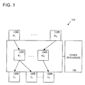
- FIG. 1 shows a configurable video presenting network 100.
- the technologies described in any of the examples herein can be used to configure the video presenting network 100.
- the video presenting network 100 for use with the technologies described herein can have one or more inputs 110A-110N (e.g., a total of ⁇ inputs, ⁇ ); two or more outputs 120A-120N (e.g., a total of T inputs, ⁇ ); and one or more digital-video-input-representation-to-video-output-signal converters 130A-130N (e.g., a total of K converters, ⁇ ).
- inputs 110A-110N e.g., a total of ⁇ inputs, ⁇
- two or more outputs 120A-120N e.g., a total of T inputs, ⁇
- digital-video-input-representation-to-video-output-signal converters 130A-130N e.g., a total of K converters, ⁇ .
- the inputs 110A-110N are sometimes called “sources” or “surfaces.”
- the outputs 120A-120N are sometimes called “targets.”
- the digital-video-input-representation-to-video-output-signal converters are sometimes called “converters.”
- the video presenting network can include other resources 140 (e.g., video memory, bandwidth, memory capacity, and the like).
- the other resources 140 can be used by the inputs, converters, and outputs to achieve video presenting functionality.
- the video presenting network 100 can be implemented in hardware such as a video display adapter (e.g., video card). In some cases, some resources may reside outside the adapter.
- a video display adapter e.g., video card
- An exemplary computer system may include one or more video views in digital form (e.g., which are written to by applications of the computer system), which are used by the inputs 110A-110N.
- the resulting signal coming from the plural outputs 120A-120N can be used to drive plural video display devices.
- Example 2 Exemplary Alternative Video Presenting Network
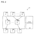
- FIG. 2 shows another configurable video presenting network 200.
- the technologies described in any of the examples herein can be used to configure the video presenting network 200.
- multiple inputs can be used for a single digital-video-input-representation-to-video-output-signal converter (e.g., the inputs 210B and 210N are used as inputs to the converter 230N).
- Such a configuration can be useful in overlaying one video signal on top of another by using a video output codec with two inputs, wherein the first input is the primary content and the second input is the overlaid content.
- the position and size of the overlay can be specified as part of the video present source mode for the video presenting network source representing the overlaid content.
- Video presenting networks can take many other forms, having an arbitrary number of inputs, converters, and plural outputs.
- Example 3 Exemplary Video Presenting Network Resources
- a resource can include video presenting network inputs (e.g., sources or surfaces), video presenting network outputs (e.g., targets), converters, video memory, bandwidth, memory capacity, and the like.
- video presenting network inputs e.g., sources or surfaces
- video presenting network outputs e.g., targets
- converters video memory, bandwidth, memory capacity, and the like.
- the topology of a video presenting network is also sometimes called a resource.
- configuring a resource can include simply choosing a topology without regard to choosing configuration options for the individual resources involved in the topology.
- Example 4 Exemplary Video Paths in a Video Presenting Network
- a video presenting network 100 can have a plurality of video paths. For example, as shown in FIG. 1, a path may be from the input 110A, through the converter 130A, to the output 120A. Another path may be from the input 110A through the converter 130A, to the output 120B, and so forth.
- the topology of the video presenting network 100 can be configured so that there are different paths according to the configuration. For example, instead of sending the output of the converter 130N to the video output 120N, it could be routed to a different video output (e.g., 120B) by changing a configuration setting.
- a different video output e.g. 120B
- Example 5 Exemplary Video Presenting Network Inputs
- the video inputs can take any of a variety of forms, such as those providing digital surfaces.
- the inputs can be configured to use a variety of source modes.
- Such modes can include parameters such as width, height, unit format, rasterized graphics filtering technique, primary surface chain length, the like, or some combination thereof.
- Example 6 Exemplary Video Presenting Network Outputs
- the video outputs can take any of a variety of forms, such as those providing output signals.
- a descriptor can be associated with the outputs.
- the descriptor can indicate a format (e.g., DVI, HDMI, HD-15, BNC, S-video, RF, RCA and the like) and HPD awareness.
- the output can also be associated with a video encoding type.
- an output can be configured to be in sync with another output.
- the outputs can be configured to use a variety of target mades.
- Such modes can include parameters such as active region (e.g., width and height), total region (e.g., width and height), active region displacement, pixel encoding format, vertical retrace frequency, horizontal retrace frequency, pixel clock rate, content ordering, color primaries, white point reference, color space transformation matrix, the like, or some combination thereof.
- a digital-video-input-representation-to-video-output-signal converter can take the form of a video codec, a digital-to-analog converter, or the like. Some converters are sharable. For example, in a clone (e.g., mirror) mode, a codec may send its signal to two outputs.
- any number of configurations of the video presenting network 100 are theoretically possible, only a limited number of theoretical configurations are functional configurations. In practice, the resources of the video presenting network 100 are subject to configuration interdependency.
- configuring the video input 110A to be of a particular type may consume a large amount of video memory. In such a case, there may not be sufficient remaining memory for another video input (e.g., 110N) to be of the same type. For example, it may only be configurable to a type consuming less memory.
- the converters may only accept particular video input types or produce particular video output types. So, a particular input may not be functional in combination with a particular converter, and so forth.
- an obstacle to implementing a desired configuration is that it may not be functional. Further, it is not easy to determine which combinations are functional out of the myriad of theoretically possible combinations for a video presenting network having a plurality of video inputs, a plurality of converters, and a plurality of video outputs (which can be interconnected in a variety of ways).
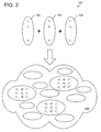
- FIG. 3 is a block diagram showing combinations of configurable resources for a video presenting network.
- the theoretically possible configurations 300 can be assembled by connecting one or more of a configured first resource 302 (e.g., a video presenting network input), with one or more of a configured second resource 304 (e.g., a video presenting network converter), that are connected with one or more of a configured third resource 306 (e.g., a video presenting network output).
- the resulting set of theoretically possible configurations 310 is shown as a vast collection of possibilities, some of which are functional, and some of which are non-functional, depending on the configuration of the resources therein.
- configuration of resources can take a wide variety of forms, including selecting a topology for a set of resources of the video presenting network or selecting configuration options (e.g., modes) for one or more resources in the network (e.g., whether or not the network is interconnected).
- FIG. 4 shows an exemplary configuration method 400 which can be used for any of the video presenting networks described herein to achieve configuration.
- the method and any of the other methods described herein can be implemented via computer-executable instructions on one or more computer-readable media.
- an indication of a configuration of a first resource of the video presenting network is received. For example, a configuration for a particular video input of the video presenting network can be received.
- an indication of a configuration for a second resource of the video presenting network is received separately from the indication of the configuration of the first resource. For example, a configuration for a particular video output of the plurality of outputs of the video presenting network can be received.
- the video presenting network is configured according to the indications of configurations.
- additional indications of configuration can be separately received for any resources of the video presenting network (e.g., for two different inputs, two different outputs, two different converters, a converter and an output, and so forth).
- Separately received indications can include those received by using two different calls, such as those to a programmatic interface (e.g., device driver interface calls). For example, two different calls to a device driver can be used. Or, two different parameters can be used in the same call. Or, one or more data structures indicating separate values for the resources can be used. Such calls can come from a client such as an operating system.
- a programmatic interface e.g., device driver interface calls.
- two different calls to a device driver can be used.
- two different parameters can be used in the same call.
- one or more data structures indicating separate values for the resources can be used.
- Such calls can come from a client such as an operating system.
- the resources of the video presenting network can be independently configured.
- Such configuration can also indicate a topology for the video presenting network (e.g., how the resources are interconnected).
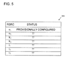
- FIG. 5 shows a table 500 indicating provisional configuration of a resource of a video presenting network such as that shown in FIG. 1.
- the resource ⁇ 1 has been provisionally configured (e.g., configuration parameters for the resource of the video presenting network are stored but the configuration need not be fully functional).
- a provisional configuration can be based on receipt of a partial configuration (e.g., a configuration of a resource out of the video presenting network resources or an indication of a topology for the video presenting network). Configuration for all resources need not be received for a provisional configuration. Because a configuration without the full set of configuration parameters is typically not yet functional, a provisional configuration is sometimes called "semi-functional.” Providing a partial configuration for a resource is sometimes called “pinning" the resource. If desired, the partial configuration can be removed (or overridden). Removing the partial configuration is sometimes called "unpinning.”
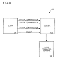
- FIG. 6 shows an exemplary arrangement 600 for achieving configuration of a video presenting network 630 (e.g., the video presenting network shown in FIG. 1) via a transactional approach.
- a client 610 can send partial configuration information for a video presenting network to a server 620.
- the server 620 can then configure the video presenting network 630 according to the indications of partial configuration.
- FIG. 7 shows an exemplary method 700 for performing configuration via a transactional approach.
- a series of partial configurations for the video presenting network are received (e.g., from a client by a server).
- the partial configurations can be used to build a provisional functional configuration.
- the provisional functional configuration is committed.
- the committing can implement the provisional functional configuration in the video presenting network (e.g., the network 630).
- a provisional functional configuration can be stored without being implemented.
- the configuration can be stored without configuring the resources of the video presenting network (e.g., until a commit configuration indication is processed).
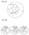
- FIG. 8A shows an exemplary set of configuration options 850 for a resource ⁇ ⁇ , out of which only a subset 860 of configuration options are available (e.g., would result in a functional configuration) in light of how another resource ⁇ 1 has been provisionally configured.
- the available configuration options are sometimes described as "co-functional" with the other configuration options (e.g., of the provisional functional configuration) or "not invalidating" a provisional configuration.
- the set of co-functional configuration options 860 for a resource can be provided as feedback during provisional configuration in a process sometimes called "enumeration.” Such feedback can then be used to make decisions regarding further configuration (e.g., to further build the provisional functional configuration or to backtrack to an earlier provisional functional configuration).
- any of the configuration methods described herein can include receiving an indication to remove a partial configuration from the provisional functional configuration and remove the partial configuration responsive to receiving the indication (or, simply a new partial configuration, which overrides the old). In this way, a method can backtrack (e.g., unpin a resource) to an earlier provisional functional configuration (e.g., before committing the provisional functional configuration).
- FICr. 8B shows an arrangement in which co-functional configuration options 880A, 880B, and 880C for respective resources (e.g., ⁇ 1 , ⁇ 2 , and ⁇ 3 ) are indicated, wherein configuration options for more than one resource at a time are indicated.
- the co-functional configuration options shown are co-functional with respect to the chosen topology.
- the options may not be co-functional with respect to each other. For example, choosing one of the co-functional options for a first resource may invalidate (e.g., not be co-functional with) another one of the co-functional options of another resource.
- At least some of the original options are no longer available (e.g., are not co-functional) in light of the chosen topology.
- options are enumerated for other resources (e.g., targets).
- Such options can be enumerated by software (e.g., a video driver).
- software e.g., a video driver
- configuration options e.g., for a plurality of resources
- pinning e.g., provisionally choosing
- one of the configuration options for a first resource may invalidate (e.g., not be co-functional with) another option for another resource.
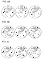
- FIGS. 9A-C show an example in which choosing a configuration option for one resource invalidates a configuration option for another resource.
- a topology can be chosen.
- FIG. 9A shows the co-functional options 920A, 920B, and 920C (e.g., subsets of theoretically possible options 910A, 920B, and 920C, respectively) enumerated after having chosen a topology.
- FIG. 9B shows that a particular option 921 has been chosen (e.g., pinned) for a first resource.
- some of the configuration options for the other resources may no longer be available (e.g., they are invalidated).
- an option no longer appears in 920B'.
- other options are invalidated.
- perhaps none are invalidated.
- FIG. 9C shows that a particular option 922 has been chosen (e.g., pinned) for another resource.
- some of the configuration options for the remaining resources may no longer be available.
- some of the options for the first resource may also be invalided (e.g., resulting in a set 920A', not shown).
- the pinned configuration option will not be invalidated by choosing another one of the enumerated configuration options.
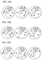
- FIGS. 10A-C show another example in which choosing a configuration option for one resource invalidates a configuration option for another resource.
- a topology can be chosen.
- FIG. 10A shows the co-functional options 1020A, 1020B, and 1020C (e.g., subsets of theoretically possible options 1010A, 1020B, and 1020C, respectively) enumerated after having chosen a topology.
- FIG. 10B shows that a particular option 1021 has been chosen (e.g., pinned) for a first resource.
- some of the configuration options for the other resources may no longer be available (e.g., they are invalidated).
- an option no longer appears in 1020B'.
- other options are invalidated.
- perhaps none are invalidated.
- FIG. 10C shows that a particular option 1022 has been chosen (e.g., pinned) for another resource.
- some of the configuration options for the remaining resources may no longer be available.
- some of the options for the first resource may also be invalided (e.g., resulting in a set 1020A', not shown).
- the pinned configuration option will not be invalidated by choosing another one of the enumerated configuration options. Many other scenarios are possible.
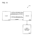
- FIG. 11 shows an exemplary arrangement 1100 for achieving configuration of a video presenting network 1130 (e.g., the video presenting network shown in FIG. 1) via a transactional approach with feedback.
- a video presenting network 1130 e.g., the video presenting network shown in FIG. 1
- a client 1110 can send partial configuration information for a video presenting network to a server 1120.
- the partial configuration information can be for any of the resources of the video presenting network.
- the partial configuration can indicate a topology of the video presenting network.
- co-functional configuration options e.g., for a second resource
- the co-functional configuration options can be for a different resource than the partial configuration, for a resource in a different path, and the like.
- the co-functional options can be restricted (e.g., at least one non-co-functional option is removed) based on the configuration information.
- the options can be provided via enumeration, and enumeration can be done for plural resources at a time.
- the co-functional configuration options for the other resource(s) can be based on interdependencies between the resources of the video presenting network.
- the client can select from among the co-functional configuration options and continue to build a provisional functional configuration.
- the server 1120 can then configure the video presenting network 1130 according to the indications of partial configuration.
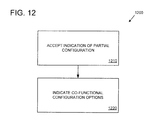
- FIG. 12 shows an exemplary method 1200 for performing configuration with feedback from a server perspective.
- the method can operate via the arrangement shown in FIG. 11.
- an indication of a partial video network presenting configuration is received.
- the partial configuration can indicate a configuration for a first resource of the video presenting network.
- co-functional configuration options are indicated (e.g., as described for FIGS. 11A or 11B, above).
- all configuration options may be indicated with the exception of one or more non-co-functianal configuration options, which would be removed from the options indicated before the options are indicated.
- the method can also include a commit (not shown) by which the configuration is committed to the video presenting network.
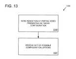
- FIG. 13 shows an exemplary method 1300 for performing configuration with feedback from a client perspective.
- the method can operate via the arrangement shown in FIG. 11.
- an indication of a partial video presenting network configuration is sent.
- the partial configuration can indicate a configuration for a first resource of the video presenting network.
- a set of co-functional configuration options (e.g., as described for FIGS. 11A or 11B, above) are indicated.
- the method can also include a commit (not shown) by which the configuration is committed to the video presenting network.
- Example 18 Exemplary Server Implementation in Video Driver
- Determining co-functional configuration options can be delegated to a video driver.
- actions performed by the server can be performed by a video driver (e.g., a video miniport).
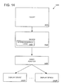
- FIG. 14 shows an exemplary architecture 1400 in which provisional configuration with feedback can be implemented.
- the example includes a client 1410 (e.g., an operating system, such as the graphics subsystem, an application, or the like), a driver 1420 (e.g., a device-specific video driver operating in kernel mode) with interdependency logic 1425, and a video adapter 1430, which provides video output to plural display devices 1440A - 1440N.
- a client 1410 e.g., an operating system, such as the graphics subsystem, an application, or the like
- driver 1420 e.g., a device-specific video driver operating in kernel mode
- interdependency logic 1425 e.g., a device-specific video driver operating in kernel mode
- the video driver 1420 can serve as a server in any of the examples described herein.
- the interdependency logic 1425 can include functions for accepting partial configurations, enumerating co-functional configuration options, and committing a configuration.
- a hardware vendor of a display adapter can develop an appropriate driver 1420 that incorporates the appropriate interdependency logic 1425 to aid in determining a desirable video presenting network configuration.
- interdependency logic in a video driver can simplify determining an appropriate configuration by reducing the scope for a given hardware implementation with a certain set of limitations. If the logic were instead in the operating system, the task can be more complex (e.g., need to be completely generic and support every possible interdependency).
- Example 20 Exemplary Configuration of Video Presenting Network
- FIG. 15 shows an exemplary method 1500 for configuration of a video presenting network via partial configuration.
- a topology for the video presenting network is chosen.
- configurations options for the sources are enumerated and pinned.
- configuration options for the targets are enumerated and pinned.
- a commit (not shown) can be used to implement the configuration.
- sources are sometimes shown as pinned before targets, such need not be the case.
- targets can be pinned before sources.
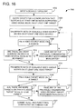
- FIG. 16 shows a flowchart of an exemplary method 1600 of traversing a graph of possible functional multiple video output configuration combinations.
- a method can be used by a client (e.g., the client 1410) interacting with a server (e.g., video driver 1420).
- a server e.g., video driver 1420
- the example shows a video miniport, but another video driver (e.g., video driver 1420) can be used.
- the example also includes a fixed topology functional video presenting network configuration search, but other examples may include an option of changing the topology during the search.
- a topology may be desired to be changed after the pinning of a video present source mode on a video presenting network source invalidates at least one other video present source mode for another video presenting network source.
- a video miniport is queried for a video presenting network configuration (e.g., topology) that supports at least one monitor-supported video signal mode (e.g., all modes) on at least one video presenting network target (e.g., all targets).
- a video presenting network configuration e.g., topology
- monitor-supported video signal mode e.g., all modes
- the sets of available video present source modes on at least one video present source e.g., all sources
- the obtained video presenting network configuration e.g., topology
- a video present source mode is pinned on at least one video presenting network source (e.g., all sources).
- At 1612 it is determined whether any of the previously enumerated video present source modes has been invalidated. If so, the process returns to 1606. If not, the process returns to 1608. In the example, at least one of the previously enumerated video present source modes can be invalidated based on the selection of another video present source mode, but not all of the video present source modes can be invalidated by such a selection.
- the sets of available video present target modes on at least one video present target (e.g., all targets) in the obtained video presenting network configuration are enumerated.
- a video present target mode is pinned on at least one video presenting network target (e.g., all targets).
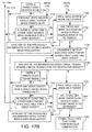
- FIGs. 17A-B show a flowchart of a first exemplary detailed method 1700 of traversing a graph of possible functional multiple video output configuration combinations.
- a method can be used by a client (e.g., the client 1410) interacting with a server (e.g., video driver 1420).
- the example shows a video miniport, but another video driver (e.g., video driver 1420) can be used.
- a video miniport is queried for a video presenting network configuration (e.g., toplogy) that supports at least one monitor-supported video signal mode (e.g., all modes) on at least one video presenting network target (e.g., all targets).
- a video presenting network configuration e.g., toplogy
- monitor-supported video signal mode e.g., all modes
- the sets of available video present source modes on at least one video presenting network source (e.g., all sources) in the obtained video presenting network configuration are enumerated. The process then proceeds to 1722.
- the video presenting network topology is adjusted to a new valid video presenting network topology by the addition or removal of a video presenting path (e.g., multi-path).
- a video presenting path e.g., multi-path.
- the video present source mode unpinning at 1728 can be ordered according to video presenting network source importance (e.g., the source modes can be prioritized from most to least important).
- the video present source mode pinning at 1732 can be ordered according to video presenting network source importance (e.g., the source modes can be prioritized from most to least important).
- the sets of available video present target modes on at least one video presenting network target (e.g., all targets) in the obtained video presenting network configuration are enumerated.
- the video present target mode unpinning at 1748 can be ordered according to video presenting network target importance (e.g., the target modes can be prioritized from most to least important).
- the video present target mode pinning at 1752 can be ordered according to video presenting network target importance (e.g., the target modes can be prioritized from most to least important).
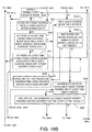
- FIGs. 18A-C shows a flowchart of a first exemplary detailed method 1800 of traversing a graph of possible functional multiple video output configuration combinations.
- a method can be used by a client (e.g., the client 1410) interacting with a server (e.g., video driver 1420).
- the example shows a video miniport, but another video driver (e.g., video driver 1420) can be used.
- a video miniport is queried for a video presenting network configuration (e.g., topology) that supports at least one monitor-supported video signal mode (e.g., all modes) on at least one video presenting network target (e.g., all targets).
- a video presenting network configuration e.g., topology
- monitor-supported video signal mode e.g., all modes
- the sets of available video present source modes on at least one video presenting network source (e.g., all sources) in the obtained video presenting network configuration are enumerated. The process then proceeds to 1822.
- the video presenting network topology is adjusted to a new valid video presenting network topology by the addition or removal of a video presenting path (e.g., multi-path).
- a video presenting path e.g., multi-path.
- the video present source mode unpinning at 1828 can be ordered according to video presenting network source importance (e.g., the source modes can be prioritized from most to least important).
- the video present source mode pinning at 1832 can be ordered according to video presenting network source importance (e.g., the source modes can be prioritized from most to least important).
- the sets of available video present target modes on at least one video presenting network target (e.g., all targets) in the obtained video presenting network configuration are enumerated.
- the video present target mode unpinning at 1848 can be ordered according to video presenting network target importance (e.g., the target modes can be prioritized from most to least important).
- the video present target mode pinning at 1852 can be ordered according to video presenting network target importance (e.g., the target modes can be prioritized from most to least important).
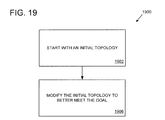
- FIG. 19 shows a flowchart showing an exemplary method 1900 of determining a topology for a video presenting network in light of a goal (e.g., stated in terms of video modes supported by monitors).
- the process starts with an initial topology.
- the initial topology is modified to better meet the goal (e.g., by generating a provisional functional configuration better meeting the goal). Such modifications can take into account interdependencies among resources of the video presenting network.
- a goal can be the best way to route video presenting network targets to video presenting network sources in a video presenting network through the available video output codecs to maximize supported graphics video presenting network source mode sets on its video presenting network sources, given that video mode sets on the video presenting network targets must support preferred modes on all the monitors connected to them.
- the goal can be the best way to route video presenting network targets to video presenting network sources in a video presenting network through the available video output codecs to maximize supported graphics video presenting network source mode sets on its video presenting network sources, given that video mode sets on the video presenting network targets must support preferred modes on the monitors connected to them in a specified prioritization ordering.
- the goal can be the best way to route video presenting network targets to video presenting network sources in a video presenting network through the available video output codecs to maximize supported graphics video presenting network source mode sets on its video presenting network sources, given that video mode sets on the video presenting network targets must support at least one of the video modes supported by the monitors connected to them.
- a first goal can be attempted. Then, if the first goal cannot be met, a second goal can be attempted, and so forth.
- a goal is sometimes described as an "optimal" configuration.
- Such goals are beyond the scope of a simple video driver, such goals can be achieved by placing decision-making ability outside of the video driver (e.g., in the upper layers of the operating system, such as in the shell, graphics subsystem, DX runtime, and the like).
- a query or a traversal approach can be used to achieve configuration goals.
- an implicit goal in any configuration is that the video outputs support at least one mode supported by the respective monitor. Unless overridden by performance or power management considerations, it is typically a further goal that video outputs try to support preferred modes of their respective monitors, where the monitor's importance is prioritized by the client (e.g., operating system) as part of the configuration request.
- the client e.g., operating system
- the video driver should attempt to have as many monitors to run in their preferred modes, only sharing codecs when doing otherwise means one of the requested outputs can not be driven.
- Example 26 Exemplary Goals Related to Power Consumption
- a configuration with smaller power consumption may be preferred for economy power states, and performance and/or image quality may be preferred when in full-power states.
- such goals can be implemented.
- Example 27 Exemplary Device Driver Interface
- Example 45 lists a set of functions (e.g., EnumerateAvailVidPNTargets, ConstrainNodesOnVidPNTargets, etc.) and their purposes. Such functions can be included in a device driver interface supported by a video device driver (e.g., a video miniport). The functions can be used by clients to build a video presenting network in incremental fashion, employing various algorithms (e.g., search algorithms).
- functions e.g., EnumerateAvailVidPNTargets, ConstrainNodesOnVidPNTargets, etc.
- Such functions can be included in a device driver interface supported by a video device driver (e.g., a video miniport).
- the functions can be used by clients to build a video presenting network in incremental fashion, employing various algorithms (e.g., search algorithms).
- Example 28 Exemplary Functions for Configuration Management
- Example 45 details a set of functions for configuration management.
- a function e.g., GetActiveVidPNTopology
- a video presenting network configuration e.g., a topology
- Another function e.g., CommitVidPNImpl
- Another function e.g., EnumCurrentlyAvailVidPNSourceModeSets
- EnumCurrentlyAvailVidPNSourceModeSets enumerates video present source modes available given a desired video presenting network configuration.
- Another function e.g., EnumCurrentlyAvailVidPNTargetModeSets
- Another function pins a video present source mode on a video presenting network source.
- Another function e.g., PinModeOnVidPNTarget
- Another function e.g., UnpinModeOnVidPNSource
- Another function e.g., UnpinModeOnVidPNTarget
- Another function e.g., UnpinModeOnVidPNTarget
- Another function e.g., CreateVidPNImpl
- Any combination of the functions can be implemented as part of a programmatic interface (e.g., a device driver interface). Such an interface can provide access to the functions as a service (e.g., for client programs).
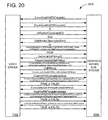
- FIG. 20 shows a block diagram showing exemplary calls to arrive at a configuration. Such calls can be implemented as part of a device driver interface (DDI).
- DCI device driver interface
- System 2000 includes communication between a driver 2002 (e.g., video miniport) and a graphics kernel subsystem 2004.
- a driver 2002 e.g., video miniport
- EnumAvailVidPNTargets can be called to enumerate available video presenting network targets supported by a given video card.
- EnumAvailVidPNSources can be called to enumerate available video presenting network sources supported by the given video card.
- These two calls can be part of a system initialization. Alternatively, these two calls can be part of a video adapter arrival event (e.g., PCI express or docking station hot-plug).
- a null video presenting network configuration modality can be supported, signifying that all available video presenting targets and sources should be reported (e.g., as is appropriate for initialization).
- IsMonitorConnected can be used to determine which of the enumerated video presenting targets have a monitor connected to them.
- GetMonitorDescriptor can be called for each of the connected monitors to obtain each respective monitor's descriptor.
- ConstrainModesOnVidPNTargets can be called to set video mode constraints on each of the enumerated video presenting targets in line with the monitor capabilities obtained from the monitors' descriptors.
- GetInitialVidPNImpl can optionally be called to obtain a video presenting network provisional configuration recommended by the video miniport.
- CreateVidPNImpl can be called to create a video presenting network provisional configuration based on the optional recommendation by the video miniport.
- CreateVidPNImpl can create a video presenting network provisional configuration disregarding the optional recommendation by the miniport.
- EnumCurrentlyAvailVidPNSourceModeSets, PinModeOnVidPNSource, and UnpinModeOnVidPNSource can be called until video presenting source modes are pinned on the video presenting network sources, as part of creating a semi-functional video presenting network. If video presenting source modes to be pinned are known to work for the video presenting network sources, PinModeOnEachVidPNSource can be called to pin video presenting source modes on all the video presenting network sources at once.
- EnumCurrentlyAvailVidPNTargetModeSets, PinModeOnVidPNTarget, and UnpinModeOnVidPNTarget can be called until video presenting target modes are pinned on the video presenting network targets, as part of completing a functional video presenting network. If video presenting target modes to be pinned are known to work for the video presenting network targets, PinModeOnEachVidPNTarget can be called to pin video presenting target modes on all the video presenting network targets at once.
- CommitVidPNImpl may be called.
- a functional video presenting network provisional configuration may be committed after primary surface chains have been set up for each source in the video presenting network.
- CommitVidPNImpl might require as input other OS-owned resources outside of the video presenting network topology and video presenting sources and targets (e.g., primary surface chains).
- Example 30 Exemplary Separation of Video Output and Render Target
- An interface that a video rendering device driver exposes need not differentiate between the notion of a video output on which the video rendering device is physically driving the displayed image and a render target to which the application is logically rendering the content it wants to be presented as two separate, independent entities.
- the render target can be implicitly and statically associated with each video output on the video rendering device. However, such an approach can be limiting.
- a display mode that is the basic operational modality descriptor of any device in an operating system can be described as two things: a video mode, which is an output modality descriptor (for an output or target, such as those shown in FIG. 1 or FIG. 25), and a rendering mode, which is an input modality descriptor (for an input or source, such as those shown in FIG. 1 or FIG. 25).
- a video mode which is an output modality descriptor (for an output or target, such as those shown in FIG. 1 or FIG. 25)
- a rendering mode which is an input modality descriptor (for an input or source, such as those shown in FIG. 1 or FIG. 25).
- Such an approach is particularly useful in system with multiple video outputs.
- Interfaces to the video driver e.g., a DDI
- logical render targets can be dynamically managed separately from the physical video outputs.
- the targets can be mapped to video outputs of choice in runtime, redirecting them from output to output as needed, or even mapping a single render target simultaneously to multiple outputs.
- any of the technologies described herein can be applied to scenarios in which a monitor is attached to or removed from a system while it is running.
- events e.g., HPD events
- changes to redirect video streams to different outputs e.g., for clone view, extended desktop management, and the like
- Robust support for such dynamic configuration changes can be accomplished by managing logical render targets separately from the physical video outputs as described herein.
- the video display devices can take a variety of forms.
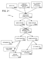
- FIG. 21 shows an exemplary integration of the technology into a computer system having a plurality of video display devices.
- FIG. 21 is a diagram of an exemplary high-level architecture of a multiple video output device system 2100.
- a desktop 2110, a display properties applet 2112, and a full-screen graphics application 2114 communicate with a graphics subsystem 2120.
- the graphics subsystem 2120 drives a video driver 2130 and another video driver 2132.
- Both video drivers e.g., video miniports
- video adapters 2150 and 2152 which send outputted signals to any combination of multiple video output devices.
- video output devices can include a CRT monitor 2160, a flat-panel monitor 2162, a digital projector 2164, an LCD monitor 2166, a pair of virtual reality goggles 2168, and the like. Other combinations than those shown are possible.
- Example 33 Exemplary Traversal of Solution Space to Converge on Desired Configuration
- FIG. 22 shows a client-server system 2200 in which a video configuration is determined based on priorities.
- a client 2202 communicates with a server 2204.
- the client 2202 contains priorities 2206 that specify prioritization information.
- Such prioritization information can include a list of one or more desired topologies, a list of desired modes for respective sources, a list of desired modes for respective targets, the like, or some combination thereof. Prioritization information can also include whether certain source modes are more important than topology selection. Additionally, the source modes desired and the target modes desired can be prioritized (e.g., from most to least important).
- priorities can be in the form of a prioritized list. However, the priorities can also be achieved by incorporation into logic (e.g., if-then statements in the client 2202).
- FIG. 23 shows an exemplary method 2300 for determining a video configuration based on a prioritized list of desired video configuration options, such as in the system shown above in FIG. 22.
- a partial video configuration for at least a first resource is submitted.
- a modified partial configuration is re-submitted for the first resource.
- a trade-of between priorities may be desirable.
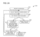
- FIG. 24 shows a flowchart of another exemplary method 2400 of traversing a graph of possible functional multiple video output configuration combinations.
- the example includes the possibility of changing the topology during determination of a desired functional video presenting network provisional configuration.
- a particular topology is selected.
- a video present source mode is selected and pinned on a video present source.
- a video present target mode is selected and pinned on a video present target.
- the method can then end (e.g., after a commit).
- the logic implemented in the example and demonstrated in FIG. 24 may be altered to accommodate multiple video present sources and/or multiple video present targets, similar to that demonstrated above and in FIG. 16.
- the logic implemented at 2410-2414 in FIG. 24 can be inserted between 1608 and 1610 and/or between 1616 and 1618 in FIG. 16.
- the search begins with an initial topology, as is done at 2402 in FIG. 24.
- a video present source mode can be pinned on the video present path's video presenting network source before a video present target mode can be pinned on the video present path's video presenting network target.
- a search can start with a single source-view video present path, pin modes on both the source and the target, and then grow the topology by adding another video present path to it.
- the topology can be changed when only the video present source mode is pinned.
- Exemplary execution of the configuration service can proceed to configure a video presenting network.
- the example assumes a video presenting network with three sources in its topology and the following video present source mode sets enumerated for each of the three sources:
- Supposing the client is interested in getting the highest possible spatial resolution on each of the video presenting network sources, the first video presenting network source being most important, the second video presenting network source being the second-most important, and the third and last video presenting network source being of least importance, it would proceed to pin the highest mode on the first video presenting network source, which is (4, 1280x1024).
- the client invalidates modes (4, 1280x1024), (5, 1600 x 1200) , and (6,2000x1500) on the second video presenting network source. Since the client isn't yet aware of this, it will try and pin the highest mode previously enumerated on the second video presenting network source (e.g., (6, 2000x1500)), which will fail with a status code stating that the specified video present source mode has been invalidated.
- the client will re-enumerate the available video present source modes across all the video presenting network sources, obtaining the following three sets:
- the client would then proceed to pin the highest available video present source mode on the second video presenting network source (e.g., (3, 1024x768)). To support this additional mode, however, the video card can no longer support neither (2, 800x600) nor (3, 1024x768) on the third video presenting network source.
- the client will try to pin the highest mode previously enumerated for that video present source (e.g., (3, 1024x768)). Failing that, the client will re-enumerate the available modes across all sources, getting:
- the client can either accept this source mode distribution and proceed to pin target modes to arrive at a functional video presenting network, or it may decide that 640x480 spatial resolution isn't high enough for it and backtrack to find a more suitable solution (e.g., one that perhaps doesn't involve setting 1280x1024 spatial resolution on the first video presenting network source, or alternatively, one that has only 2 video presenting network sources in its topology).
- the above algorithm uses a simplistic Greedy approach for rendering multi-mode convergence, and that it doesn't employ back-tracking.
- a more complicated search e.g., a depth-first search
- the above algorithm assumes a desired topology is fixed through the convergence process, such as in the exemplary method 1600 in FIG. 16.
- Example 36 Exemplary Multi-Monitor / Multi-View System
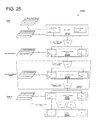
- FIG. 25 is a diagram of an exemplary multi-monitor/multi-view system 2500, which can be described using the following formalism.
- VidPN is used in place of "video presenting network”
- video present'' is used in place of "video presenting.”
- implementation is sometimes used to refer to a provisional configuration.
- the system 2500 can be used with any of the examples described herein.
- Certain ( view, output ) pairs may be factored into video present sources, which can represent inputs into video output codecs (e.g., CRTC DAC, TMDS) and video present targets, which can represent video outputs on a video card (e.g., HD-15, DVI, S-video).
- video output codecs e.g., CRTC DAC, TMDS
- video present targets e.g., HD-15, DVI, S-video
- a display mode may be factored into a video present source mode, which can specify the primary surface format via which a graphics stack is providing rendered content to be presented for a user, and a video present target mode, which can specify a video signal format driven on a respective video output.
- Video presenting capabilities of a multiple-output video card are modeled via the notion of a Video Present Network (VidPN), which can relate a set of video present sources to a set of video present targets via a VidPN topology .
- VidPN Video Present Network
- a VidPN may be considered semi-functional iff video present source modes are pinned on each of its video present sources.
- a VidPN may be considered functional iff it is semi-functional, and video present target modes are pinned on each of its video present targets.
- Association between a single video present source and a single video present target can be called a video present path.
- Association between a single video present source and multiple video present targets can be called a video present multipath.
- a video miniport's job in the context of display mode management, can be described as managing an active VidPN that represents a state of a video present configuration on a respective video card it is driving, as well as servicing clients' requests aimed at incrementally building functional VidPNs, each of which could be set as active.
- Changing display modes on monitors attached to a multiple-output video card may no longer suffer from a "single-output operation" view of the world, where video miniport developers had to implement complex synchronization among certain video driver stacks that were driving the same underlying physical device, and may be superseded with an explicit transaction-based commit of a functional VidPN implementation on a given video card serviced by a single video driver stack.
- a multiple output video display mode solution may depend on multiple criteria such as: (a) hardware limitations (e.g., video mode sets supported by monitors connected to respective video present targets); (b) operational mode considerations (e.g., specific video modes preferred by monitors connected to respective video present targets); (c) performance considerations (e.g., rendering performance improvements achieved through reduction of contention for a video memory bus by video output codecs); (d) power management considerations (e.g., reduction of a video card's power consumption achieved by disabling unutilized video output codecs, and throttling down its capabilities); (e) heat dissipation considerations (e.g., reduction of a video card's operational temperature achieved through continuous interswitching among multiple units, where one unit is given a chance to cool down while another one is operational, and vice versa, thus never increasing the number of J/sec radiated by the video card beyond a certain desired upper bound); and (f) usability considerations (e.g., a driving monitor's preferred mode on
- DVI LCD DVI LCD
- S-video HDTV S-video HDTV
- HD-15 CRT/3D glasses a user might prefer to work/read/browse on DVI LCD that has the best clarity, watch movies on S-video HDTV that has the largest active pixel region, and play games on HD-15 CRT/3D glasses that support the highest refresh rates and best gaming experience.
- a non-brute force approach for a general case of T video present targets, K codecs, and ⁇ video present sources may be analogous to a classical tri-partite graph matching problem, which is known to be NPC (e.g., there is no known algorithm that runs in polynomial time and finds an ideal, or globally optimal, solution). Determining an approximate solution as close as possible to an ideal solution is desirable.
- Determining which configurations are functional can be a complex task. For example, for a given configuration, the following may need to be considered:
- Some of the issues making the search complex are that codes are a scarce resource, and there are usually less codecs than outputs, so for clone-view it is beneficial to share a single codec across multiple outputs, whenever possible.
- Such an approach has a downside of forcing the same video mode on both monitors which may not work, if the monitors do not have a common video mode that the both support (e.g., a CRT can go up to 1280x 1024 and an LCD may support only 1600x1200). Even if they do share a video mode, such might not be the ideal way to drive the monitors, since the video mode might not be their preferred mode.
- a projector supports 640x480, 800 ⁇ 600, 1024 ⁇ 768 (native), and 1280 ⁇ 1024.
- the LCD supports 640x480, 800x600, 1024x768, 1280 ⁇ 1024, and 1400 ⁇ 1050 (native). Sharing a codec between these two means only one driver can be driven at its preferred video mode.
- an LCD might support 1024 ⁇ 768, 1280 ⁇ 1024, 1600 ⁇ 1200 (preferred).
- a projector might support 640x480, 800 ⁇ 600 (preferred), and 1024x768. Sharing means that neither monitor can be driven at its preferred mode.
- codecs are created equal. Sometimes a video card has different codecs, with one being able to do more modes or perform some of them better than the other. The situation can become even more complicated with certain modes being available on certain codecs (e.g., one codec can do only 16-bit, and another codec can do only 32-bit modes).
- cross-bar can be used to reroute codecs to different outputs
- its limitations and incompatibility of the codec with the video output's technology can result in certain codecs being restricted to certain subsets of outputs (e.g., CRTC can not drive DVI, and TMDS can not drive HD-15 of S-video).
- determining whether a particular provisional configuration is functional for the video adapter can be accomplished by (e.g., delegated to) the device driver.
- a possible alternative is to construct a general-case generic solution that can handle determination across a set of video adapters (e.g., all known video adapters). However, such a solution would require logic for handling a vast number of scenarios.
- the device driver can be made more lightweight and need not solve the general case.
- the device driver need not contain logic for handling scenarios that the corresponding video adapter cannot implement (e.g., are not present in hardware).
- the size of the device driver can be reduced and its performance (e.g., speed) can be increased (e.g., as compared to a general solution).
- a topology can be treated as a configurable resource, wherein the options (e.g., video present paths) can be configured concurrently. Compare to those video preset sources/targets in which only a single option (e.g., source/target mode) can be configured at once. Modes can be mutually exclusive within a given mode set, whereas present paths need not be necessarily mutually exclusive, but can be.
- a query-based approach may involve querying a display miniport for a solution that satisfies a set of requirements provided by the OS.
- a traversal-based approach may involve navigating through a solution space by incrementally building up a functional VidPN implementation with desired video present target and source modes chosen for its targets and sources, respectively. Determining a near-optimal implementation of a VidPN may be left to a video miniport.
- an OS may supply a video miniport with: (1) a video present target mode set requirement for each VidPN target that has a monitor connected to it (e.g., a video card must not expose video signal modes not supported by an attached monitor), conformance to which on the DDI side can be validated by the OS during video present target mode enumeration; and (2) a video present target mode set guideline to support monitors' preferred monitor source modes based on a supplied prioritization scheme, where a display miniport may find a VidPN implementation where a preferred monitor source mode is supported on a more preferable monitor first, with the preferred monitor source mode support on every monitor connected to the system being the ideal solution.
- Finding a near-optimal distribution of graphics video present source modes supported on VidPN sources may be left to a graphics subsystem's client (e.g., Shell), where a driver merely exposes an ability to traverse respective video present source mode sets distribution solution space through an API reporting a video card's capabilities under a specified operational state.
- a graphics subsystem's client e.g., Shell
- Approaches as simple as Greedy or as complex as graph-based searches may be employed.
- Example 44 Exemplary Computing Environment
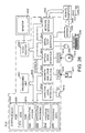
- FIG. 26 and the following discussion are intended to provide a brief, general description of an exemplary computing environment in which the disclosed technology may be implemented.
- the disclosed technology will be described in the general context of computer-executable instructions, such as program modules, being executed by a personal computer (PC).
- program modules include routines, programs, objects, components, data structures, etc. that perform particular tasks or implement particular abstract data types.
- the disclosed technology may be implemented with other computer system configurations, including hand-held devices, multiprocessor systems, microprocessor-based or programmable consumer electronics, network PCs, minicomputers, mainframe computers, and the like.
- the disclosed technology may also be practiced in distributed computing environments where tasks are performed by remote processing devices that are linked through a communications network.
- program modules may be located in both local and remote memory storage devices.
- an exemplary system for implementing the disclosed technology includes a general purpose computing device in the form of a conventional PC 2600, including a processing unit 2602, a system memory 2604, and a system bus 2606 that couples various system components including the system memory 2604 to the processing unit 2602.
- the system bus 2606 may be any of several types of bus structures including a memory bus or memory controller, a peripheral bus, and a local bus using any of a variety of bus architectures.
- the system memory 2604 includes read only memory (ROM) 2608 and random access memory (RAM) 2610.
- ROM read only memory
- RAM random access memory
- a basic input/output system (BIOS) 2612 containing the basic routines that help with the transfer of information between elements within the PC 2600, is stored in ROM 2608.
- the PC 2600 further includes a hard disk drive 2614 for reading from and writing to a hard disk (not shown), a magnetic disk drive 2616 for reading from or writing to a removable magnetic disk 2617, and an optical disk drive 2618 for reading from or writing to a removable optical disk 2619 (such as a CD-ROM or other optical media).
- the hard disk drive 2614, magnetic disk drive 2616, and optical disk drive 2618 are connected to the system bus 2606 by a hard disk drive interface 2620, a magnetic disk drive interface 2622, and an optical drive interface 2624, respectively.
- the drives and their associated computer-readable media provide nonvolatile storage of computer-readable instructions, data structures, program modules, and other data for the PC 2600.
- Other types of computer-readable media which can store data that is accessible by a PC such as magnetic cassettes, flash memory cards, digital video disks, CDs, DVDs, RAMs, ROMs, and the like, may also be used in the exemplary operating environment.
- a number of program modules may be stored on the hard disk, magnetic disk 2617, optical disk 2619, ROM 2608, or RAM 2610, including an operating system 2630, one or more application programs 2632, other program modules 2634, and program data 2636.
- a user may enter commands and information into the PC 2600 through input devices such as a keyboard 2640 and pointing device 2642 (such as a mouse).
- Other input devices may include a digital camera, microphone, joystick, game pad, satellite dish, scanner, or the like.
- serial port interface 2644 that is coupled to the system bus 2606, but may be connected by other interfaces such as a parallel port, game port, or universal serial bus (USB).
- a monitor 2646 or other type of display device is also connected to the system bus 2606 via an interface, such as a video adapter 2648.
- Other peripheral output devices such as speakers and printers (not shown), may be included.
- the PC 2600 may operate in a networked environment using logical connections to one or more remote computers, such as a remote computer 2650.
- the remote computer 2650 may be another PC, a server, a router, a network PC, or a peer device or other common network node, and typically includes many or all of the elements described above relative to the PC 2600, although only a memory storage device 2652 has been illustrated in FIG. 26.
- the logical connections depicted in FIG. 26 include a local area network (LAN) 2654 and a wide area network (WAN) 2656.
- LAN local area network
- WAN wide area network
- the PC 2600 When used in a LAN networking environment, the PC 2600 is connected to the LAN 2654 through a network interface 2658. When used in a WAN networking environment, the PC 2600 typically includes a modem 2660 or other means for establishing communications over the WAN 2656, such as the Internet.
- the modem 2660 which may be internal or external, is connected to the system bus 2606 via the serial port interface 2644.
- program modules depicted relative to the personal computer 2600, or portions thereof may be stored in the remote memory storage device.
- the network connections shown are exemplary, and other means of establishing a communications link between the computers may be used.
- a video presenting network is sometimes called a "video present network” or "VidPN.”
- VidPN implementation A particular configuration for the video present network is sometimes called a "VidPN implementation.”
- Function Text_Rendering_Format Name TEXT_RENDERING_FORMAT Purpose Text video present source mode format. Definition typedef TBD TEXT_RENDERING_FORMAT; Remarks Text video present source modes are only supported for backwards compatibility.
- the video driver handling multiple monitors can be asked to provide a recommended functional configuration.
- the relative importance of the monitors can be specified.
- the monitors can be ranked (e.g., most important to least important). The driver can then provide a configuration according to the relative importance as specified.
- the video driver maintains a state of the provisional configuration (e.g., as it is pinned and unpinned).
- a stateless approach can also be employed.
- the video driver need not track state (e.g., of the provisional configuration) and may be made more lightweight and less complex.
- the client software can track a state during determination of a desired configuration.
- a programming interface e.g., a DDI
- a data structure can be used to hold the configuration details and passed through the interface.
- Example 48 Exemplary Stateless Driver Interface
- the following is an exemplary kernel mode driver interface (e.g., a DDI), including a stateless video presenting network management miniport interface, for implementing a video presenting network supporting the various technologies described herein.
- a video presenting network is sometimes called a "video present network” or "VidPN.”
- VidPN implementation A particular configuration for the video present network is sometimes called a "VidPN implementation.”
- miniport is used, but the technologies described within can be applied to any display adapter or video driver.
- An exemplary kernel mode driver can be part of a video miniport.
- Each physical GPU can be treated as its own adapter, where the adapter can be represented by the HANDLE hAdapter retrieved below. If a single GPU has multiple outputs (e.g., heads), it may still be treated as a single adapter.
- a miniport's HwVidQueryInterface function can be called with the following QUERY_INTERFACE structure to retrieve driver entry points:
- the HwVidQueryInterface call returns NO_ERROR if the interface was successfully retrieved; otherwise it should return the appropriate error code.
- the driver entry points can be returned in the D3DKMDDI_INTERFACE structure below. Querying the interface may implicitly reference it. Thus, if initialization of the driver fails after the interface has been queried, the interface dereference function can be called without the driver having seen an explicit reference.
- the returned hAdapter in the D3DKMDDI_INTERFACE structure can be passed as the context for pInterfaceReference and pInterfaceDereference. It can also be passed in the hAdapter parameter for the adapter functions in the interface.
- the interface specific data can contain pointers to callback functions in the runtime that the driver can call.
- the hAdapter can be the runtime's adapter handle and can be passed for callbacks requesting an adapter handle.
- EnumVideoPresentSourceSet can be called for each display adapter in the system by the VidPN manager instance that is driving the post-rendering video presentational capabilities of the respective display adapter in order to obtain a list of video present sources that the specified display adapter has.
- the miniport can allocate a large enough buffer in system memory to contain the requested set of video present sources for the specified display adapter using the AllocSysMemForOutParamCb callback provided to it by the operating system via the INTERFACESPECIFICDATA interface.
- the size of the allocation should be sizeof(D3DKMDDI_VIDEO_PRESENT_SOURCE_SET)+ sizeof(D3DKMDDI_VIDEO_PRESENT_SOURCE) * (# of video present sources - 1).
- the miniport can populate it based on the definitions below:
- the operating system can take ownership of the lifetime of the data returned in the output parameter and can deallocate the memory taken by its supporting allocation when it is done with it.
- STATUS_SUCCESS indicates that the driver handled the call successfully.
- EnumVideoPresentTargetSet can be called for each display adapter in the system by the VidPN manager instance that is driving the post-rendering video presentational capabilities of the respective display adapter in order to obtain a list of video present targets that the specified display adapter has.
- the miniport can allocate a large enough buffer in system memory to contain the requested set of video present sources for the specified display adapter using the AllocSysMemForOutParamCb callback provided to it by the operating system via the INTERFACESPECIFICDATA interface.
- the size of the allocation should be sizeof(D3DKMDDI_VIDEO_PRESENT_TARGET_SET) + sizeof(D3DKMDDI_VIDEO_PRESENT_TARGET) * (# of video present targets - 1).
- the miniport can populate it based on the definitions below:
- the video output technology type descriptor can be defined as:
- the video output HPD awareness descriptor type can be defined as:
- Video output HPD awareness can be used to represent the level of monitor connectivity sensed by a display adapter on its video output, and with the following four types available:
- Monitor orientation awareness can be defined as:
- the operating system can take ownership of the lifetime of the data returned in the output parameter and can deallocate the memory taken by its supporting allocation when it is done with it.
- STATUS_SUCCESS indicates that the driver handled the call successfully.
- IsSupportedVidPN can allow the operating system to ask the miniport whether the provided VidPN configuration is supported (e.g., can be extended to a functional VidPN).
- the first argument, hAdapter can specify the display adapter on which the VidPN support is in question.
- the actual VidPN can be specified in the first field of the second argument, pIsSupportedVidPNArg->pDesiredVidPN, where the VidPN descriptor can be defined as:
- the VidPN topology descriptor can be defined as:
- VidPNPresentPathSet can represent the set of video present paths constituting the VidPN's topology, where: with:
- the VidPN present path descriptor can be defined as:
- D3DKMDDI_VIDPN_PRESENT_PATH is the video present path descriptor that can be used to describe a mapping from a single video present target to a single video present source in a VidPN topology, with:
- the VidPN source mode set descriptor can be defined as: with:
- the VidPN source mode descriptor can be defined as: with Type containing the VidPN source mode type descriptor, defined as:
- the source mode descriptor contains a graphics rendering format descriptor, grfxFormat , defined as: with:
- the source mode descriptor contains a text rendering format descriptor, textFormat , defined as: With:
- the VidPN target mode set descriptor can be defined as: with:
- the video signal standard enum can be used to simplify video mode comparisons when appropriate.
- the fractional frequency descriptor can be defined as: with:
- Vertical frequencies can be stored in Hz and horizontal frequencies can be stored in KHz.
- the dynamic range of this encoding format given 10 ⁇ -7 resolution (on 32-bit systems) is ⁇ 0.. ⁇ 2 ⁇ 32 - 1) /10 ⁇ 7 ⁇ , which translates to ⁇ 0..428.4967296 ⁇ [Hz] for vertical frequencies and ⁇ 0..428.4967296 ⁇ [KHz] for horizontal frequencies.
- the video signal scan-line ordering descriptor can be defined as: and can be used specify whether each field contains the entire content of a frame or only half of it (e.g., even/odd lines interchangeably). Specifying this characteristic explicitly with an enum can both free up the client from having to maintain mode-based look-up tables and be extensible for future standard modes not listed in the D3DKMDDI_VIDEO_SIGNAL_STANDARD enum.
- the VidPN present path transformation descriptor can be defined as: with:
- a specified VidPN should at a minimum specify a valid topology, but can also have some or all of its targets/sources configured with respectively pinned modes.
- STATUS_SUCCESS indicates that the driver handled the call successfully.
- STATUS_GRAPHICS_INVALID_VIDPN_TOPOLOGY indicates that the specified VidPN topology is invalid.
- EnumCofuncVidPNSourceIDSet enumerates a set of VidPN source IDs confunctional with the specified VidPN implementation.
- a VidPN source can be cofunctional with a given VidPN implementation if an only if it can be added to its topology via at least one video present path without rendering that VidPN implementation invalid or unsupported.
- the miniport can allocate a large enough buffer pointed to by pEnumCofuncVidPNSourceIDSetArg to accommodate the entire enumeration result using D3DKMDDI_INTERFACESPECIFICDATA.pfnAllocSysMemForOutParamCb.
- the size of the allocation should be sizeof(D3DKMDDI_VIDEO_PRESENT_SOURCE_ID_SET)+ sizeof(D3DKMDDI_VIDEO_PRESENT_SOURCE_ID) * (# of cofunctional video present sources - 1).
- the miniport can populate it based on the definitions below: with:
- the operating system can take ownership of the lifetime of the data returned in the output parameter and can deallocate the memory taken by its supporting allocation when it is done with it.
- STATUS_SUCCESS indicates that the driver handled the call successfully.
- STATUS_GRAPHICS_INVALID_VIDPN_TOPOLOGY indicates that the specified VidPN topology is invalid.
- STATUS_NO_MEMORY indicate that miniport could not allocate a buffer to fit in the requested enumeration.
- EnumCofuncVidPNTargetIDSet enumerates a set of VidPN target IDs confunctional with the specified VidPN implementation.
- a VidPN target can be cofunctional with a given VidPN implementation if and only if it can be added to its topology via at least one video present path without rendering that VidPN implementation invalid or unsupported.
- the miniport can allocate a large enough buffer pointed to by pEnumCofuncVidPNTargetIDSetArg to accommodate the entire enumeration result using D3DKMDDI_INTERFACESPECIFICDATA.pfnAllocSysMemForOutParamCb.
- the size of the allocation should be sizeof(D3DKMDDI_VIDEO_PRESENT_TARGET_ID_SET) + sizeof(D3DKMDDI_VIDEO_PRESENT_TARGET_ID) * (# of cofunctional video present targets - 1).
- the miniport can populate it based on the definitions below: with:
- the operating system can take ownership of the lifetime of the data returned in the output parameter and can deallocate the memory taken by its supporting allocation when it is done with it.
- STATUS_SUCCESS indicates that the driver handled the call successfully.
- STATUS_GRAPHICS_INVALID_VIDPN_TOPOLOGY indicates that the specified VidPN topology is invalid.
- STATUS_NO_MEMORY indicates that the miniport could not allocate a buffer to fit in the requested enumeration.
- EnumVidPNCofuncModality lets the operating system enumerate cofunctional video present and target mode sets on each video present path in the specified VidPN, where:
- the miniport should populate:
- the operating system can take ownership of the lifetime of the data returned in the output parameter and can deallocate the memory taken by its supporting allocation when it is done with it.
- STATUS_SUCCESS indicates that the driver handled the call successfully.
- STATUS_NO_MEMORY indicate that miniport could not allocate a buffer to fit in the requested enumeration.
- RecommendFunctionalVidPN lets the operating system query for a VidPN recommended by the miniport, given the current state of the h/w.
- the operating system may use it in case it encounters a configuration where no user preference (e.g., last-used modality) has been specified.
- the operating system specifies to the miniport a vector of VidPN targets IDs, pVidPNTargetPrioritizationVector ordered most important first, representing the relative importance of monitors connected to them.
- the miniport should allocate sufficient memory to populate the functional VidPN it wishes to recommend to the operating system for the current state of the h/w, populate the respective fields, and assign its address to pRecommendedFunctionalVidPN.
- the operating system can take ownership of the lifetime of the data returned in the output parameter and can deallocate the memory taken by its supporting allocation when it is done with it.
- STATUS_SUCCESS indicates that the driver handled the call successfully.
- STATUS_GRAPHICS_NO_RECOMMENDED_VIDPN indicates that miniport has no VidPN recommendation for the current configuration of the display adapter.
- STATUS_NO_MEMORY indicates that the miniport could not allocate a buffer to fit in the requested enumeration.
- Example 49 Exemplary Device-Specific Part of Video Rendering Device Driver
- Any of the technologies described herein can be implemented in the device-specific part of a video rendering device driver.
- a reusable portion of the driver can be shared across video rendering device drivers.
- the video port can serve as the reusable portion of the driver, and a video miniport can serve as the device-specific part of the video rendering device driver.
- Multi-monitor display mode management is a complex problem that deals with capabilities of video rendering/presenting devices (e.g., video cards also known as graphics adapters) and video monitoring devices (e.g., monitors).
- video rendering/presenting devices e.g., video cards also known as graphics adapters
- video monitoring devices e.g., monitors.
- a main issue causing complexity in display mode management is an inherent interdependency among capabilities of graphics display device objects (e.g., MICROSOFT® WINDOWS® GDI objects), each representing a separate ( view , output) mapping on a single multi-output video card, which is not dealt with well by the legacy display mode management architecture.
- graphics display device objects e.g., MICROSOFT® WINDOWS® GDI objects
- two main abstractions that may be made with respect to multi-output video cards are: (1) a simplified view of a multi-function display device abstraction that includes both the video card and the monitor, represented in a unified "display mode" descriptor modality, which contains states of two distinct physical devices; and (2) extension of a single-output mode enumeration to multiple outputs, which can be achieved via duplication of independent video driver stacks and respective graphics devices, one per (view, output).
Landscapes
- Engineering & Computer Science (AREA)
- Theoretical Computer Science (AREA)
- Physics & Mathematics (AREA)
- Automation & Control Theory (AREA)
- Signal Processing (AREA)
- Multimedia (AREA)
- Software Systems (AREA)
- General Engineering & Computer Science (AREA)
- General Physics & Mathematics (AREA)
- Computer Networks & Wireless Communication (AREA)
- Computer Hardware Design (AREA)
- Data Mining & Analysis (AREA)
- Databases & Information Systems (AREA)
- Mathematical Physics (AREA)
- Two-Way Televisions, Distribution Of Moving Picture Or The Like (AREA)
- Controls And Circuits For Display Device (AREA)
- Color Television Systems (AREA)
Applications Claiming Priority (10)
| Application Number | Priority Date | Filing Date | Title |
|---|---|---|---|
| US567053 | 1983-12-30 | ||
| US56705304P | 2004-04-30 | 2004-04-30 | |
| US10/925,859 US8581803B2 (en) | 2004-04-30 | 2004-08-24 | Video presenting network management |
| US925837 | 2004-08-24 | ||
| US925445 | 2004-08-24 | ||
| US10/925,662 US7898533B2 (en) | 2004-04-30 | 2004-08-24 | Video presenting network configuration solution space traversal |
| US925662 | 2004-08-24 | ||
| US10/925,445 US7903045B2 (en) | 2004-04-30 | 2004-08-24 | Video presenting network supporting separately-configurable resources |
| US925859 | 2004-08-24 | ||
| US10/925,837 US7679612B2 (en) | 2004-04-30 | 2004-08-24 | Configuration goals via video presenting network |
Publications (2)
| Publication Number | Publication Date |
|---|---|
| EP1591892A2 true EP1591892A2 (fr) | 2005-11-02 |
| EP1591892A3 EP1591892A3 (fr) | 2012-08-15 |
Family
ID=34939631
Family Applications (1)
| Application Number | Title | Priority Date | Filing Date |
|---|---|---|---|
| EP05103623A Withdrawn EP1591892A3 (fr) | 2004-04-30 | 2005-05-02 | Gestion d'un réseau pour la présentation de vidéo |
Country Status (4)
| Country | Link |
|---|---|
| EP (1) | EP1591892A3 (fr) |
| JP (1) | JP4927348B2 (fr) |
| KR (1) | KR101117871B1 (fr) |
| CN (1) | CN1716194B (fr) |
Cited By (3)
| Publication number | Priority date | Publication date | Assignee | Title |
|---|---|---|---|---|
| CN102129477A (zh) * | 2011-04-23 | 2011-07-20 | 山东大学 | 一种多模态联合的图像重排序方法 |
| JP6131376B1 (ja) * | 2016-10-28 | 2017-05-17 | 株式会社計測技術研究所 | 信号入出力処理装置 |
| CN112362332A (zh) * | 2020-11-27 | 2021-02-12 | 歌尔科技有限公司 | 一种游戏手柄摇杆校准测试装置及校准测试方法 |
Families Citing this family (3)
| Publication number | Priority date | Publication date | Assignee | Title |
|---|---|---|---|---|
| CA2948105A1 (fr) * | 2014-05-09 | 2015-11-12 | Nokia Technologies Oy | Procede et equipement technique d'encodage et de decodage video au moyen d'un codage de palette |
| CN109346014B (zh) * | 2018-09-29 | 2020-07-03 | 歌尔科技有限公司 | 一种虚拟现实设备及其屏幕控制方法 |
| CN112380386A (zh) * | 2020-11-19 | 2021-02-19 | 深圳Tcl新技术有限公司 | 视频搜索方法及装置、终端、计算机可读存储介质 |
Family Cites Families (10)
| Publication number | Priority date | Publication date | Assignee | Title |
|---|---|---|---|---|
| GB2271253A (en) * | 1992-10-03 | 1994-04-06 | Ibm | Data compression at a video conference computer workstation |
| JPH06274292A (ja) * | 1993-03-18 | 1994-09-30 | Fuji Xerox Co Ltd | プリンタ選択基準表示装置 |
| US5787246A (en) | 1994-05-27 | 1998-07-28 | Microsoft Corporation | System for configuring devices for a computer system |
| CN1156379A (zh) * | 1995-11-07 | 1997-08-06 | 索尼公司 | 视频显示装置 |
| US6028643A (en) * | 1997-09-03 | 2000-02-22 | Colorgraphic Communications Corporation | Multiple-screen video adapter with television tuner |
| US6556253B1 (en) * | 1999-10-26 | 2003-04-29 | Thomson Licensing S.A. | Multi-window picture adjustment arrangement for a video display |
| JP2000132361A (ja) | 1999-11-24 | 2000-05-12 | Seiko Epson Corp | プリンタ検索装置及びその方法 |
| US7460086B1 (en) * | 1999-12-13 | 2008-12-02 | Honeywell International Inc. | Multiple and hybrid graphics display types |
| JP3643078B2 (ja) | 2002-01-18 | 2005-04-27 | 東日本電信電話株式会社 | 設備情報のシステム間照合装置及び方法 |
| US7134040B2 (en) | 2002-04-17 | 2006-11-07 | International Business Machines Corporation | Method, system, and program for selecting a path to a device to use when sending data requests to the device |
-
2005
- 2005-04-29 KR KR1020050036291A patent/KR101117871B1/ko not_active Expired - Fee Related
- 2005-04-30 CN CN2005100896871A patent/CN1716194B/zh not_active Expired - Fee Related
- 2005-05-02 EP EP05103623A patent/EP1591892A3/fr not_active Withdrawn
- 2005-05-02 JP JP2005134489A patent/JP4927348B2/ja not_active Expired - Fee Related
Non-Patent Citations (1)
| Title |
|---|
| None * |
Cited By (4)
| Publication number | Priority date | Publication date | Assignee | Title |
|---|---|---|---|---|
| CN102129477A (zh) * | 2011-04-23 | 2011-07-20 | 山东大学 | 一种多模态联合的图像重排序方法 |
| CN102129477B (zh) * | 2011-04-23 | 2013-01-09 | 山东大学 | 一种多模态联合的图像重排序方法 |
| JP6131376B1 (ja) * | 2016-10-28 | 2017-05-17 | 株式会社計測技術研究所 | 信号入出力処理装置 |
| CN112362332A (zh) * | 2020-11-27 | 2021-02-12 | 歌尔科技有限公司 | 一种游戏手柄摇杆校准测试装置及校准测试方法 |
Also Published As
| Publication number | Publication date |
|---|---|
| KR20060047658A (ko) | 2006-05-18 |
| CN1716194B (zh) | 2010-06-09 |
| JP2006018803A (ja) | 2006-01-19 |
| KR101117871B1 (ko) | 2012-04-13 |
| CN1716194A (zh) | 2006-01-04 |
| EP1591892A3 (fr) | 2012-08-15 |
| JP4927348B2 (ja) | 2012-05-09 |
Similar Documents
| Publication | Publication Date | Title |
|---|---|---|
| US20110149161A1 (en) | Video presenting network configuration solution space traversal | |
| US7679612B2 (en) | Configuration goals via video presenting network | |
| KR101713177B1 (ko) | 가상 디스플레이들에 대한 시스템 및 방법 | |
| US10031712B2 (en) | System and method for display mirroring | |
| US7903045B2 (en) | Video presenting network supporting separately-configurable resources | |
| US20130215142A1 (en) | Apparatus and method for displaying an image on a sink device | |
| EP1591892A2 (fr) | Gestion d'un réseau pour la présentation de vidéo | |
| EP2606640A1 (fr) | Système et procédé permettant de mettre des flux audio et vidéo provenant d'une source audio/vidéo en correspondance avec plusieurs blocs récepteurs audio/vidéo | |
| US8581803B2 (en) | Video presenting network management | |
| US8984540B2 (en) | Multi-user computer system | |
| US20120219070A1 (en) | System and method for a thin-client terminal system with a local screen buffer using a serial bus | |
| US20050050252A1 (en) | Information processing apparatus | |
| US12386576B2 (en) | Display method and electronic device | |
| US20130335636A1 (en) | Method for outputting image and electronic device for using the same | |
| CN115866293A (zh) | 一种视频分析方法和视频分析系统 | |
| TWI598817B (zh) | 多用戶電腦系統 | |
| CN120726956A (zh) | 一种背光亮度调整方法及电子设备 |
Legal Events
| Date | Code | Title | Description |
|---|---|---|---|
| PUAI | Public reference made under article 153(3) epc to a published international application that has entered the european phase |
Free format text: ORIGINAL CODE: 0009012 |
|
| AK | Designated contracting states |
Kind code of ref document: A2 Designated state(s): AT BE BG CH CY CZ DE DK EE ES FI FR GB GR HU IE IS IT LI LT LU MC NL PL PT RO SE SI SK TR |
|
| AX | Request for extension of the european patent |
Extension state: AL BA HR LV MK YU |
|
| PUAL | Search report despatched |
Free format text: ORIGINAL CODE: 0009013 |
|
| RIC1 | Information provided on ipc code assigned before grant |
Ipc: G06F 9/445 20060101AFI20120704BHEP Ipc: G06F 3/14 20060101ALI20120704BHEP Ipc: G06F 9/44 20060101ALI20120704BHEP |
|
| AK | Designated contracting states |
Kind code of ref document: A3 Designated state(s): AT BE BG CH CY CZ DE DK EE ES FI FR GB GR HU IE IS IT LI LT LU MC NL PL PT RO SE SI SK TR |
|
| AX | Request for extension of the european patent |
Extension state: AL BA HR LV MK YU |
|
| 17P | Request for examination filed |
Effective date: 20130109 |
|
| AKX | Designation fees paid |
Designated state(s): AT BE BG CH CY CZ DE DK EE ES FI FR GB GR HU IE IS IT LI LT LU MC NL PL PT RO SE SI SK TR |
|
| RAP1 | Party data changed (applicant data changed or rights of an application transferred) |
Owner name: MICROSOFT TECHNOLOGY LICENSING, LLC |
|
| 17Q | First examination report despatched |
Effective date: 20170222 |
|
| STAA | Information on the status of an ep patent application or granted ep patent |
Free format text: STATUS: THE APPLICATION IS DEEMED TO BE WITHDRAWN |
|
| 18D | Application deemed to be withdrawn |
Effective date: 20200819 |