EP1591990B1 - Circuit de commande d'une module d'affichage et son procédé de commande - Google Patents
Circuit de commande d'une module d'affichage et son procédé de commande Download PDFInfo
- Publication number
- EP1591990B1 EP1591990B1 EP05009089A EP05009089A EP1591990B1 EP 1591990 B1 EP1591990 B1 EP 1591990B1 EP 05009089 A EP05009089 A EP 05009089A EP 05009089 A EP05009089 A EP 05009089A EP 1591990 B1 EP1591990 B1 EP 1591990B1
- Authority
- EP
- European Patent Office
- Prior art keywords
- brightness
- display
- screen
- driving
- areas
- Prior art date
- Legal status (The legal status is an assumption and is not a legal conclusion. Google has not performed a legal analysis and makes no representation as to the accuracy of the status listed.)
- Expired - Fee Related
Links
- 238000000034 method Methods 0.000 title claims description 13
- 230000003247 decreasing effect Effects 0.000 claims description 4
- 230000000452 restraining effect Effects 0.000 description 6
- 208000036762 Acute promyelocytic leukaemia Diseases 0.000 description 3
- 230000000007 visual effect Effects 0.000 description 3
- 230000004075 alteration Effects 0.000 description 2
- 238000001514 detection method Methods 0.000 description 2
- 238000012986 modification Methods 0.000 description 2
- 230000004048 modification Effects 0.000 description 2
- 230000001360 synchronised effect Effects 0.000 description 2
- CIWBSHSKHKDKBQ-JLAZNSOCSA-N Ascorbic acid Chemical compound OC[C@H](O)[C@H]1OC(=O)C(O)=C1O CIWBSHSKHKDKBQ-JLAZNSOCSA-N 0.000 description 1
- 238000010586 diagram Methods 0.000 description 1
- 230000000694 effects Effects 0.000 description 1
- 238000005401 electroluminescence Methods 0.000 description 1
- 230000012447 hatching Effects 0.000 description 1
Images


Classifications
-
- G—PHYSICS
- G09—EDUCATION; CRYPTOGRAPHY; DISPLAY; ADVERTISING; SEALS
- G09G—ARRANGEMENTS OR CIRCUITS FOR CONTROL OF INDICATING DEVICES USING STATIC MEANS TO PRESENT VARIABLE INFORMATION
- G09G3/00—Control arrangements or circuits, of interest only in connection with visual indicators other than cathode-ray tubes
- G09G3/20—Control arrangements or circuits, of interest only in connection with visual indicators other than cathode-ray tubes for presentation of an assembly of a number of characters, e.g. a page, by composing the assembly by combination of individual elements arranged in a matrix no fixed position being assigned to or needed to be assigned to the individual characters or partial characters
- G09G3/2007—Display of intermediate tones
-
- G—PHYSICS
- G09—EDUCATION; CRYPTOGRAPHY; DISPLAY; ADVERTISING; SEALS
- G09G—ARRANGEMENTS OR CIRCUITS FOR CONTROL OF INDICATING DEVICES USING STATIC MEANS TO PRESENT VARIABLE INFORMATION
- G09G3/00—Control arrangements or circuits, of interest only in connection with visual indicators other than cathode-ray tubes
- G09G3/20—Control arrangements or circuits, of interest only in connection with visual indicators other than cathode-ray tubes for presentation of an assembly of a number of characters, e.g. a page, by composing the assembly by combination of individual elements arranged in a matrix no fixed position being assigned to or needed to be assigned to the individual characters or partial characters
- G09G3/22—Control arrangements or circuits, of interest only in connection with visual indicators other than cathode-ray tubes for presentation of an assembly of a number of characters, e.g. a page, by composing the assembly by combination of individual elements arranged in a matrix no fixed position being assigned to or needed to be assigned to the individual characters or partial characters using controlled light sources
- G09G3/28—Control arrangements or circuits, of interest only in connection with visual indicators other than cathode-ray tubes for presentation of an assembly of a number of characters, e.g. a page, by composing the assembly by combination of individual elements arranged in a matrix no fixed position being assigned to or needed to be assigned to the individual characters or partial characters using controlled light sources using luminous gas-discharge panels, e.g. plasma panels
- G09G3/288—Control arrangements or circuits, of interest only in connection with visual indicators other than cathode-ray tubes for presentation of an assembly of a number of characters, e.g. a page, by composing the assembly by combination of individual elements arranged in a matrix no fixed position being assigned to or needed to be assigned to the individual characters or partial characters using controlled light sources using luminous gas-discharge panels, e.g. plasma panels using AC panels
- G09G3/296—Driving circuits for producing the waveforms applied to the driving electrodes
-
- G—PHYSICS
- G09—EDUCATION; CRYPTOGRAPHY; DISPLAY; ADVERTISING; SEALS
- G09G—ARRANGEMENTS OR CIRCUITS FOR CONTROL OF INDICATING DEVICES USING STATIC MEANS TO PRESENT VARIABLE INFORMATION
- G09G3/00—Control arrangements or circuits, of interest only in connection with visual indicators other than cathode-ray tubes
- G09G3/20—Control arrangements or circuits, of interest only in connection with visual indicators other than cathode-ray tubes for presentation of an assembly of a number of characters, e.g. a page, by composing the assembly by combination of individual elements arranged in a matrix no fixed position being assigned to or needed to be assigned to the individual characters or partial characters
- G09G3/22—Control arrangements or circuits, of interest only in connection with visual indicators other than cathode-ray tubes for presentation of an assembly of a number of characters, e.g. a page, by composing the assembly by combination of individual elements arranged in a matrix no fixed position being assigned to or needed to be assigned to the individual characters or partial characters using controlled light sources
- G09G3/30—Control arrangements or circuits, of interest only in connection with visual indicators other than cathode-ray tubes for presentation of an assembly of a number of characters, e.g. a page, by composing the assembly by combination of individual elements arranged in a matrix no fixed position being assigned to or needed to be assigned to the individual characters or partial characters using controlled light sources using electroluminescent panels
-
- G—PHYSICS
- G09—EDUCATION; CRYPTOGRAPHY; DISPLAY; ADVERTISING; SEALS
- G09G—ARRANGEMENTS OR CIRCUITS FOR CONTROL OF INDICATING DEVICES USING STATIC MEANS TO PRESENT VARIABLE INFORMATION
- G09G3/00—Control arrangements or circuits, of interest only in connection with visual indicators other than cathode-ray tubes
- G09G3/20—Control arrangements or circuits, of interest only in connection with visual indicators other than cathode-ray tubes for presentation of an assembly of a number of characters, e.g. a page, by composing the assembly by combination of individual elements arranged in a matrix no fixed position being assigned to or needed to be assigned to the individual characters or partial characters
- G09G3/34—Control arrangements or circuits, of interest only in connection with visual indicators other than cathode-ray tubes for presentation of an assembly of a number of characters, e.g. a page, by composing the assembly by combination of individual elements arranged in a matrix no fixed position being assigned to or needed to be assigned to the individual characters or partial characters by control of light from an independent source
- G09G3/36—Control arrangements or circuits, of interest only in connection with visual indicators other than cathode-ray tubes for presentation of an assembly of a number of characters, e.g. a page, by composing the assembly by combination of individual elements arranged in a matrix no fixed position being assigned to or needed to be assigned to the individual characters or partial characters by control of light from an independent source using liquid crystals
-
- H—ELECTRICITY
- H04—ELECTRIC COMMUNICATION TECHNIQUE
- H04N—PICTORIAL COMMUNICATION, e.g. TELEVISION
- H04N21/00—Selective content distribution, e.g. interactive television or video on demand [VOD]
- H04N21/40—Client devices specifically adapted for the reception of or interaction with content, e.g. set-top-box [STB]; Operations thereof
- H04N21/43—Processing of content or additional data, e.g. demultiplexing additional data from a digital video stream; Elementary client operations, e.g. monitoring of home network or synchronising decoder's clock; Client middleware
- H04N21/431—Generation of visual interfaces for content selection or interaction; Content or additional data rendering
- H04N21/4318—Generation of visual interfaces for content selection or interaction; Content or additional data rendering by altering the content in the rendering process, e.g. blanking, blurring or masking an image region
-
- H—ELECTRICITY
- H04—ELECTRIC COMMUNICATION TECHNIQUE
- H04N—PICTORIAL COMMUNICATION, e.g. TELEVISION
- H04N5/00—Details of television systems
- H04N5/44—Receiver circuitry for the reception of television signals according to analogue transmission standards
- H04N5/57—Control of contrast or brightness
-
- G—PHYSICS
- G09—EDUCATION; CRYPTOGRAPHY; DISPLAY; ADVERTISING; SEALS
- G09G—ARRANGEMENTS OR CIRCUITS FOR CONTROL OF INDICATING DEVICES USING STATIC MEANS TO PRESENT VARIABLE INFORMATION
- G09G2320/00—Control of display operating conditions
- G09G2320/02—Improving the quality of display appearance
- G09G2320/0271—Adjustment of the gradation levels within the range of the gradation scale, e.g. by redistribution or clipping
-
- G—PHYSICS
- G09—EDUCATION; CRYPTOGRAPHY; DISPLAY; ADVERTISING; SEALS
- G09G—ARRANGEMENTS OR CIRCUITS FOR CONTROL OF INDICATING DEVICES USING STATIC MEANS TO PRESENT VARIABLE INFORMATION
- G09G2320/00—Control of display operating conditions
- G09G2320/06—Adjustment of display parameters
- G09G2320/0626—Adjustment of display parameters for control of overall brightness
-
- G—PHYSICS
- G09—EDUCATION; CRYPTOGRAPHY; DISPLAY; ADVERTISING; SEALS
- G09G—ARRANGEMENTS OR CIRCUITS FOR CONTROL OF INDICATING DEVICES USING STATIC MEANS TO PRESENT VARIABLE INFORMATION
- G09G2320/00—Control of display operating conditions
- G09G2320/06—Adjustment of display parameters
- G09G2320/066—Adjustment of display parameters for control of contrast
-
- G—PHYSICS
- G09—EDUCATION; CRYPTOGRAPHY; DISPLAY; ADVERTISING; SEALS
- G09G—ARRANGEMENTS OR CIRCUITS FOR CONTROL OF INDICATING DEVICES USING STATIC MEANS TO PRESENT VARIABLE INFORMATION
- G09G2320/00—Control of display operating conditions
- G09G2320/06—Adjustment of display parameters
- G09G2320/0686—Adjustment of display parameters with two or more screen areas displaying information with different brightness or colours
-
- G—PHYSICS
- G09—EDUCATION; CRYPTOGRAPHY; DISPLAY; ADVERTISING; SEALS
- G09G—ARRANGEMENTS OR CIRCUITS FOR CONTROL OF INDICATING DEVICES USING STATIC MEANS TO PRESENT VARIABLE INFORMATION
- G09G2330/00—Aspects of power supply; Aspects of display protection and defect management
- G09G2330/02—Details of power systems and of start or stop of display operation
- G09G2330/021—Power management, e.g. power saving
-
- G—PHYSICS
- G09—EDUCATION; CRYPTOGRAPHY; DISPLAY; ADVERTISING; SEALS
- G09G—ARRANGEMENTS OR CIRCUITS FOR CONTROL OF INDICATING DEVICES USING STATIC MEANS TO PRESENT VARIABLE INFORMATION
- G09G2360/00—Aspects of the architecture of display systems
- G09G2360/16—Calculation or use of calculated indices related to luminance levels in display data
-
- G—PHYSICS
- G09—EDUCATION; CRYPTOGRAPHY; DISPLAY; ADVERTISING; SEALS
- G09G—ARRANGEMENTS OR CIRCUITS FOR CONTROL OF INDICATING DEVICES USING STATIC MEANS TO PRESENT VARIABLE INFORMATION
- G09G3/00—Control arrangements or circuits, of interest only in connection with visual indicators other than cathode-ray tubes
- G09G3/20—Control arrangements or circuits, of interest only in connection with visual indicators other than cathode-ray tubes for presentation of an assembly of a number of characters, e.g. a page, by composing the assembly by combination of individual elements arranged in a matrix no fixed position being assigned to or needed to be assigned to the individual characters or partial characters
-
- G—PHYSICS
- G09—EDUCATION; CRYPTOGRAPHY; DISPLAY; ADVERTISING; SEALS
- G09G—ARRANGEMENTS OR CIRCUITS FOR CONTROL OF INDICATING DEVICES USING STATIC MEANS TO PRESENT VARIABLE INFORMATION
- G09G3/00—Control arrangements or circuits, of interest only in connection with visual indicators other than cathode-ray tubes
- G09G3/20—Control arrangements or circuits, of interest only in connection with visual indicators other than cathode-ray tubes for presentation of an assembly of a number of characters, e.g. a page, by composing the assembly by combination of individual elements arranged in a matrix no fixed position being assigned to or needed to be assigned to the individual characters or partial characters
- G09G3/22—Control arrangements or circuits, of interest only in connection with visual indicators other than cathode-ray tubes for presentation of an assembly of a number of characters, e.g. a page, by composing the assembly by combination of individual elements arranged in a matrix no fixed position being assigned to or needed to be assigned to the individual characters or partial characters using controlled light sources
- G09G3/28—Control arrangements or circuits, of interest only in connection with visual indicators other than cathode-ray tubes for presentation of an assembly of a number of characters, e.g. a page, by composing the assembly by combination of individual elements arranged in a matrix no fixed position being assigned to or needed to be assigned to the individual characters or partial characters using controlled light sources using luminous gas-discharge panels, e.g. plasma panels
Definitions
- the present invention relates to a drive apparatus of a display device and the drive method therefor.
- the brightness is corrected simply in accordance with the position of an area on the screen. Therefore, effects provided by the correction are plain and monotonous. Therefore, in some cases, there is little improvement in display quality depending upon a brightness distribution of a screen image, or the display quality improvement by the brightness correction is limited.
- EP-A-1 265 213 shows a display-device drive apparatus for driving a display device in accordance with a video signal and displaying a screen image on the display screen of said display device, and including: a detecting section for detecting a brightness level of the screen image of said video signal as an area brightness level for each of a plurality of display areas on said display screen; and an adjustment driving section for comparing said area brightness levels with each other and driving said display device by a driving signal representing said screen image so as to form a brightness level distribution of said screen image according to adjustment characteristics determined in accordance with the difference between the area brightness levels.
- Similar display apparatuses are disclosed in JP-A-07-210109 and JP-A-11-219152 .
- EP 08 880 004 is a prior application of the applicant and refers to a display apparatus including a plasma display panel and an automatic brightness/beam limiter.
- JP 06282241 is a further former application of the applicant and refers to another plasma display panel.
- the present invention is made to solve the above-mentioned problems, and provides a drive apparatus of the display device for making the brightness correction of the screen for raising the display quality in accordance with a brightness situation of the display screen image while restraining or decreasing the electric power consumption, and the dive method.
- the invention resides in a display-device drive apparatus for driving a display device in accordance with a video signal and displaying a screen image on the display screen of said display device, which includes a detecting section for detecting a brightness level of the screen image of said video signal as an area brightness level for each of a plurality of display areas on said display screen; and an adjustment driving section for comparing said area brightness levels with each other and driving said display device by a driving signal representing said screen image so as to form a brightness level distribution of said screen image according to adjustment characteristics determined in accordance with the difference between the area brightness levels, wherein the plurality of display areas include a central area of the display screen and a circumferential area with respect to the central area; and wherein the adjustment driving section adjusts the video signal so as to increase the brightness of one area, when the area brightness level of the one area among the plurality of display areas is higher than the area brightness levels of the other areas.
- the invention also resides in a display driving method in a display-device drive apparatus for driving a display device in accordance with a video signal and displaying a screen image on the display screen of said display device, which includes a detecting step for detecting a brightness level of the screen image of said video signal as an area brightness level for each of a plurality of display areas on said display screen; and an adjustment driving step for comparing said area brightness levels with each other and driving said display device by a driving signal representing said screen image so as to form a brightness level distribution of said screen image according to adjustment characteristics determined in accordance with the difference between the area brightness levels, wherein the plurality of display areas include a central area of the display screen and a circumferential area with respect to the central area; and wherein the adjustment driving section adjusts the video signal so as to increase the brightness of one area, when the area brightness level of the one area among the plurality of display areas is higher than the area brightness levels of the other areas.
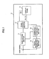
- Fig. 1 shows a drive apparatus of a display panel according to a first embodiment of the present invention.
- the display panel drive apparatus 10 may be, for example, a digital broadcast receiver of a wall hanging type, and may be also a thin-panel display device provided in an audio visual system. Otherwise, the display panel drive apparatus 10 may be also a display device provided in an in-car equipment such as a car navigation device, etc.
- a gain varying section 11 is a circuit for making a brightness correction of the video signal by multiplying a predetermined gain on the basis of commands from a correction characteristic control section 15 described later. Such correction processing can be performed by setting a different correction value of the gain for each area of a display screen.
- a panel driving section 12 includes a circuit for generating pixel data for display in a display panel 13 from the video signal corrected in brightness in the gain varying section 11, and also includes a circuit such as a frame memory, etc. for once accumulating such pixel data over one to several frames.
- the panel driving section 12 also generates a driving pulse as a driving signal synchronized with a synchronous signal included in the video signal and operating each pixel of the display panel 13 in accordance with the pixel data. Accordingly, various kinds of driver circuits for operating each electrode included in the display panel 13 by these driving pulses, and a control circuit of such drivers are also included in the panel driving section 12.
- the display panel 13 is a thin-panel display such as a PDP, and has row electrodes X1 to Xn and row electrodes Y1 to Yn constituting row electrode pairs corresponding to respective rows (first to n-th rows) on the screen in one pair of an X-electrode and a Y-electrode . Further, the display panel 13 is provided with column electrodes D1 to Dm corresponding to respective columns (first to m-th columns) on the screen and perpendicular to the above row electrode pairs, and unillustrated dielectric layers and discharge spatial layers are provided therebetween.
- One display cell C(i, j) is formed in a intersecting portion of one pair of row electrodes (Xi, Yi) and one column electrode Dj.
- Each electrode of the display panel 13 is connected to various kinds of driver circuits of the panel driving section 12, and is operated by the driving pulses supplied from the driver circuits.
- the detailed configuration of the display panel 13 is similar to that of the display panel shown, for example, in the above patent document 1.
- a block brightness detecting section 14 (hereinafter, simply referred to as a "detecting section 14") is a section for detecting brightness information in each area of the display screen.
- Various parameters can be used as such brightness information.
- APL Average Pulse Level
- APL Average Pulse Level representing an average brightness level of the video signal within a unit display period is used.
- a correction characteristic control section 15 (hereinafter, simply referred to as a "control section 15") is a section for controlling correction characteristics with respect to the brightness of the input video signal on the basis of a detection result of the detecting section 14.
- the brightness gain in the gain varying section 11 may be adjusted, or a pulse rate of the driving pulse in the panel driving section 12 may be adjusted.
- the detecting section 14 detects APL representing the brightness information with respect to each area obtained by dividing the screen into a plurality of areas.
- APL representing the brightness information with respect to each area obtained by dividing the screen into a plurality of areas.
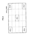
- one screen is divided into five areas, for example, with respect to each of the horizontal and vertical directions as shown in Fig. 2 , hence the screen is divided into 25 areas.
- the brightness information for five portions (hereinafter, also referred to as "blocks”) constructed by the blocks at four corners and the center of the screen.
- the detecting section 14 detects the brightnesses of the blocks at left, right, upper and lower corners of the screen as APLUL, APLUR, APLLL and APLLR.
- the calculating method of APL LOCAL is not limited to such a technique. For example, all the APLs in each block of a screen outer circumferential edge are added together and may be divided by a block number of the outer circumferential edge. Otherwise, the APLs of respective central portion blocks of the screen four corners and the screen outer circumference are added together and may be divided into eight portions and APL LOCAL may be calculated.
- the detecting section 14 detects the brightness in the block of the screen center as a central portion brightness APL CENTER .
- APL CENTER may be also calculated by including APLs of a plurality of blocks surrounding the block of the screen central portion instead of simple use of only one block of the central portion.
- the control section 15 performs the following control of the correction characteristics of a brightness gain on the basis of the detecting result of the brightness information using the detecting section 14.
- the control section 15 sends to the gain varying section 11 commands for executing the correction characteristics of the brightness gain set in advance in the gain varying section 11.
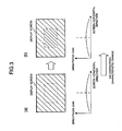
- the brightness gain correction in the gain varying section 11 in this case will be schematically described in Fig. 3 .
- the brightness correction characteristic of a so-called "circumferential portion brightness drop" as shown as shown in the lower portions of (a) and (b) of Fig. 3 is set as a reference correction characteristic in advance in the gain varying section 11.
- the correction using the "circumferential portion brightness drop" is a correction in which the brightness gain of the circumferential portion of the screen is set to be lower than that of the central portion of the screen.
- Ahighbrightness feeling can be added by making such a correction with respect to the display screen image on the screen while restraining electric power consumption by utilizing a visual tendency of a human in which the human is likely to notice the screen central portion in comparison with the screen circumferential portion.
- the brightness gain correction shown in Fig. 3 illustrates only in the horizontal direction of the screen, but a correction characteristic having a similar tendency is also set with respect to the vertical direction.
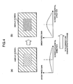
- control section 15 sends commands to the gain varying section 11 for changing the reference correction characteristics set in the gain varying section 11. A correction of the brightness gain in this case will be described based on Figs. 4 and 5 .
- the control section 15 when the brightness of the central portion of the screen is a large value exceeding the predetermined threshold value in comparison with the brightness of the circumferential portion, the control section 15 further increases the brightness gain deviation of the reference correction characteristics under the screen in (b) of Fig. 4 , and sends commands for control for providing the correction characteristics as shown in the lower part of (b) of Fig. 4 to the gain varying section 11.
- the brightness of the screen central portion is further emphasized and the brightness distribution of the screen as shown in (b) of Fig. 4 is attained.
- the correction characteristic is also similarly changed with respect to a case in which the brightness of the central portion of the screen is smaller than a predetermined threshold value in comparison with the brightness of the circumferential portion.
- the brightness of the central portion of the screen is increased in comparison with that before the correction, and a high brightness feeling as the entire screen is obtained.
- the screen brightness correction is performed by correcting the brightness gain in the gain varying section 11 as an example.
- the control section 15 may alsomake the brightness correction by controlling a mode of the driving pulse for the panel driving section 12.
- the control section 15 may also make the brightness correction on the screen by giving control commands for adjusting a parameter with respect to the driving signal such as a repeating frequency, a pulse width, etc. of a discharge maintaining pulse to the panel driving section 12.
- different correction characteristics are set with respect to each of the horizontal and vertical directions of the screen, and the correction characteristics may be also independently changed in accordance with the brightness difference between blocks in each of the horizontal and vertical directions. Further, the correction characteristics may be also set with an arbitrary area of the screen as a reference instead of the correction characteristics of the brightness with the central portion of the display screen as a reference. In the above description, the correction characteristics are shown by a waveform continuously changed in the horizontal to vertical directions. However, for example, as shown in Fig. 7 , correction characteristics having a brightness gain stepwise changed every each block in the horizontal to vertical directions may be also set.
- the correction using the normal circumferential brightness drop is made.
- the correction for emphasizing the brightness of the screen central portion is made. Therefore, a high brightness feeling can be given to a user while restraining electric power consumption.
- the correction characteristics are changed in accordance with the brightness difference between respective blocks on the screen similarly to the first embodiment.
- the correction characteristics of the circumferential brightness drop are not adjusted as in the first embodiment, but the feature of the embodiment is in that the display quality of a screen image is improved while restraining electric power consumption by emphasizing the contrast of each area.
- the detecting section 14 detects brightness information on the screen, and detects the brightness APL LOCAL of a circumferential portion and the brightness APL CENTER of a central portion.
- the calculating method of APL LOCAL and APL CENTER is set similarly to that in the first embodiment.
- the control section 15 gives commands for control for making a correction for increasing the brightness gain of the screen central portion and reducing the brightness gain of the screen circumferential portion to the gain varying section 11.
- An image of the correction characteristics at this time is shown under the screen in (a) of Fig. 8 .
- the brightness distribution of the screen after the correction attains the state shown in (b) of Fig. 8 by such a correction, and the contrast between the brightness of the screen central portion and the brightness of the circumferential portion is further clarified.
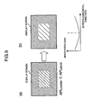
- the control section 15 sends commands for control for making a correction for reducing the brightness gain of the screen central portion and increasing the brightness gain of the screen circumferential portion to the gain varying section 11.
- the correction characteristics at this time is schematically shown in (b) of Fig. 9 .
- the brightness distribution of the screen after the correction attains the state shown in (b) of Fig. 9 by such a correction, and the contrast between the brightness of the central portion of the screen and the brightness of the circumferential portion is further clarified.
- the brightness gain correction shown in Figs. 8 and 9 is shown only in the horizontal direction of the screen, but a correction characteristic having a similar tendency is also set in the vertical direction of the screen.
- the brightness difference between the central portion and the circumferential portion of the screen is further emphasized by making such a correction, and the contrast of the display image is strengthened. Therefore, a high brightness feeling can be given to a user while restraining electric power consumption.
- the screen brightness is controlled by adjusting the brightness gain in the gain varying section 11 as an example.
- the control section 15 may also control the brightness by giving commands for controlling the driving pulse with respect to the panel driving section 12.
- the control section 15 may also make the brightness correction on the screen by giving commands for control for adjusting a parameter with respect to the driving signal such as a repeating frequency, a pulse width, etc. of a discharge maintaining pulse to the panel driving section 12.
- correction characteristics are set with respect to each of the horizontal direction and the vertical direction of the screen, and the correction characteristics may be also independently changed in accordance with the brightness difference between blocks in each of the horizontal and vertical directions.
- the correction characteristics with an arbitrary area of the screen as a reference may be also set instead of the correction characteristics of the brightness with the central portion of the display screen as a reference.
- the correction characteristics are shown by a waveform continuously changed. However, for example, correction characteristics having a brightness gain stepwise changed every each block may be also set.
Landscapes
- Engineering & Computer Science (AREA)
- Physics & Mathematics (AREA)
- Theoretical Computer Science (AREA)
- Computer Hardware Design (AREA)
- General Physics & Mathematics (AREA)
- Signal Processing (AREA)
- Multimedia (AREA)
- Power Engineering (AREA)
- Plasma & Fusion (AREA)
- Chemical & Material Sciences (AREA)
- Crystallography & Structural Chemistry (AREA)
- Control Of Indicators Other Than Cathode Ray Tubes (AREA)
- Control Of Gas Discharge Display Tubes (AREA)
- Transforming Electric Information Into Light Information (AREA)
- Controls And Circuits For Display Device (AREA)
Claims (8)
- Appareil de commande de dispositif d'affichage pour commander un dispositif d'affichage (13) en fonction d'un signal vidéo et afficher une image d'écran sur l'écran d'affichage dudit dispositif d'affichage, et comprenant :une section de détection (14) pour détecter un niveau de luminosité de l'image d'écran dudit signal vidéo en tant que niveau de luminosité de zone pour chacune d'une pluralité de zones d'affichage sur ledit écran d'affichage et pour calculer un niveau de luminosité d'une portion centrale comprenant au moins l'une desdites zones et d'une portion circonférentielle par rapport à ladite portion centrale comprenant au moins l'une desdites zones ; etune section de commande d'ajustement (12, 15) pour comparer lesdits niveaux de luminosité de portion entre eux et commander ledit dispositif d'affichage par un signal de commande représentant ladite image d'écran dont la luminosité a été corrigée en fonction de la différence entre les niveaux de luminosité de portion calculés, dans lequel :lorsque la valeur absolue de la différence entre les niveaux de luminosité calculés de la portion circonférentielle et de la portion centrale est inférieure à une valeur de seuil prédéterminée, la section de commande d'ajustement applique une correction de luminosité de sorte que le facteur de correction appliqué à la portion centrale soit supérieur au facteur de correction appliqué à la portion circonférentielle ; etlorsque la valeur absolue de la différence entre les niveaux de luminosité calculés de la portion circonférentielle et de la portion centrale est supérieure à une valeur de seuil prédéterminée, la section de commande d'ajustement applique une correction de luminosité de sorte que la différence entre le facteur de correction appliqué à la portion centrale et le facteur de correction appliqué à la portion circonférentielle soit en outre accrue.
- Appareil de commande de dispositif d'affichage pour commander un dispositif d'affichage (13) en fonction d'un signal vidéo et afficher une image d'écran sur l'écran d'affichage dudit dispositif d'affichage, et comprenant :une section de détection (14) pour détecter un niveau de luminosité de l'image d'écran dudit signal vidéo en tant que niveau de luminosité de zone pour chacune d'une pluralité de zones d'affichage sur ledit écran d'affichage et pour calculer un niveau de luminosité d'une portion centrale comprenant au moins l'une desdites zones et d'une portion circonférentielle par rapport à ladite portion centrale comprenant au moins l'une desdites zones ; etune section de commande d'ajustement (12, 15) pour comparer lesdits niveaux de luminosité de portion entre eux et commander ledit dispositif d'affichage par un signal de commande représentant ladite image d'écran dont la luminosité a été corrigée en fonction de la différence entre les niveaux de luminosité de portion calculés, dans lequel :lorsque le niveau de luminosité calculé d'une portion est supérieur au niveau de luminosité calculé de l'autre portion, la section de commande d'ajustement ajuste ledit signal vidéo de manière à accroître la luminosité de la portion de niveau de luminosité supérieur calculé tout en réduisant la luminosité de l'autre portion.
- Appareil de commande de dispositif d'affichage selon la revendication 1 ou 2, dans lequel ladite section de commande d'ajustement (12, 15) ajuste de manière à réduire les luminosités des zones circonférentielles, lorsque la différence de niveau entre les niveaux de luminosité des zones circonférentielles et de la zone centrale est inférieure à une valeur de seuil prédéterminée.
- Appareil de commande de dispositif d'affichage selon la revendication 1 ou 2, dans lequel ladite section de commande d'ajustement ajuste de manière à accroître la luminosité de la zone centrale, lorsque la différence de niveau entre la luminosité de la zone circonférentielle et la luminosité de la zone centrale est supérieure ou égale à une valeur de seuil prédéterminée.
- Appareil de commande de dispositif d'affichage selon la revendication 1 ou 2, dans lequel la luminosité de la zone circonférentielle est la valeur moyenne des luminosités des zones circonférentielles de la zone centrale.
- Appareil de commande de dispositif d'affichage selon la revendication 1 ou 2, dans lequel ladite section de détection détecte une valeur APL pour chacune de ladite pluralité de zones d'affichage en tant que ledit niveau de luminosité de zone, la valeur APL représentant un niveau de luminosité moyen du signal vidéo au cours d'une période d'affichage unitaire.
- Procédé de commande d'affichage dans un appareil de commande de dispositif d'affichage pour commander un dispositif d'affichage en fonction d'un signal vidéo et afficher une image d'écran sur l'écran d'affichage dudit dispositif d'affichage, le procédé de commande d'affichage comprenant :une étape de détection pour détecter un niveau de luminosité de l'image d'écran dudit signal vidéo en tant que niveau de luminosité de zone pour chacune d'une pluralité de zones d'affichage sur ledit écran d'affichage et pour calculer un niveau de luminosité d'une portion centrale comprenant au moins l'une desdites zones et d'une portion circonférentielle par rapport à ladite portion centrale comprenant au moins l'une desdites zones ; etune étape de commande d'ajustement pour comparer lesdits niveaux de luminosité de portion entre eux et commander ledit dispositif d'affichage par un signal de commande représentant ladite image d'écran dont la luminosité a été corrigée en fonction de la différence entre les niveaux de luminosité de portion calculés, dans lequel :lorsque la valeur absolue de la différence entre les niveaux de luminosité calculés de la portion circonférentielle et de la portion centrale est inférieure à une valeur de seuil prédéterminée, la section de commande d'ajustement applique une correction de luminosité de sorte que le facteur de correction appliqué à la portion centrale soit supérieur au facteur de correction appliqué à la portion circonférentielle ; etlorsque la valeur absolue de la différence entre les niveaux de luminosité calculés de la portion circonférentielle et de la portion centrale est supérieure à une valeur de seuil prédéterminée, la section de commande d'ajustement applique une correction de luminosité de sorte que la différence entre le facteur de correction appliqué à la portion centrale et le facteur de correction appliqué à la portion circonférentielle soit en outre accrue.
- Procédé de commande d'affichage dans un appareil de commande de dispositif d'affichage pour commander un dispositif d'affichage en fonction d'un signal vidéo et afficher une image d'écran sur l'écran d'affichage dudit dispositif d'affichage, le procédé de commande d'affichage comprenant :une étape de détection pour détecter un niveau de luminosité de l'image d'écran dudit signal vidéo en tant que niveau de luminosité de zone pour chacune d'une pluralité de zones d'affichage sur ledit écran d'affichage et pour calculer un niveau de luminosité d'une portion centrale comprenant au moins l'une desdites zones et d'une portion circonférentielle par rapport à ladite portion centrale comprenant au moins l'une desdites zones ; etune étape de commande d'ajustement pour comparer lesdits niveaux de luminosité de portion entre eux et commander ledit dispositif d'affichage par un signal de commande représentant ladite image d'écran dont la luminosité a été corrigée en fonction de la différence entre les niveaux de luminosité de portion calculés, dans lequel :lorsque le niveau de luminosité calculé d'une portion est supérieur au niveau de luminosité calculé de l'autre portion, la section de commande d'ajustement ajuste ledit signal vidéo de manière à accroître la luminosité de la portion de niveau de luminosité calculé supérieur tout en réduisant la luminosité de l'autre portion.
Applications Claiming Priority (2)
| Application Number | Priority Date | Filing Date | Title |
|---|---|---|---|
| JP2004131152A JP2005315956A (ja) | 2004-04-27 | 2004-04-27 | 表示器駆動装置及び駆動方法 |
| JP2004131152 | 2004-04-27 |
Publications (2)
| Publication Number | Publication Date |
|---|---|
| EP1591990A1 EP1591990A1 (fr) | 2005-11-02 |
| EP1591990B1 true EP1591990B1 (fr) | 2012-09-12 |
Family
ID=34935733
Family Applications (1)
| Application Number | Title | Priority Date | Filing Date |
|---|---|---|---|
| EP05009089A Expired - Fee Related EP1591990B1 (fr) | 2004-04-27 | 2005-04-26 | Circuit de commande d'une module d'affichage et son procédé de commande |
Country Status (4)
| Country | Link |
|---|---|
| US (1) | US20050248594A1 (fr) |
| EP (1) | EP1591990B1 (fr) |
| JP (1) | JP2005315956A (fr) |
| KR (1) | KR100708250B1 (fr) |
Families Citing this family (22)
| Publication number | Priority date | Publication date | Assignee | Title |
|---|---|---|---|---|
| EP1809032A4 (fr) * | 2004-11-05 | 2010-01-27 | Panasonic Corp | Dispositif de transformation de signal vidéo et dispositif d affichage vidéo |
| KR100745982B1 (ko) | 2006-06-19 | 2007-08-06 | 삼성전자주식회사 | 자발광형 디스플레이의 전력 저감을 위한 영상 처리 장치및 방법 |
| KR100803545B1 (ko) * | 2006-07-20 | 2008-02-15 | 엘지전자 주식회사 | 플라즈마 디스플레이 패널의 구동장치 및 그 구동방법 |
| KR101323433B1 (ko) * | 2006-12-20 | 2013-10-29 | 엘지디스플레이 주식회사 | 액정 표시 장치 및 이의 구동 방법 |
| KR101350410B1 (ko) * | 2007-02-22 | 2014-01-23 | 엘지디스플레이 주식회사 | 영상보상회로와, 이를 포함하는 액정표시장치 및 이의구동방법 |
| KR100936862B1 (ko) | 2007-12-31 | 2010-01-15 | 삼성에스디아이 주식회사 | 디스플레이 계조 표현 장치 및 계조 표현 방법 |
| JP4743234B2 (ja) | 2008-07-02 | 2011-08-10 | ソニー株式会社 | 表示装置及び表示方法 |
| US8576260B2 (en) * | 2008-11-12 | 2013-11-05 | Panasonic Corporation | Plasma display device and plasma display panel driving method |
| KR101246413B1 (ko) * | 2008-11-13 | 2013-03-22 | 파나소닉 주식회사 | 플라즈마 디스플레이 장치 및 플라즈마 디스플레이 패널의 구동 방법 |
| US8471786B2 (en) | 2008-11-13 | 2013-06-25 | Panasonic Corporation | Plasma display device and plasma display panel driving method |
| WO2010067412A1 (fr) * | 2008-12-09 | 2010-06-17 | 日立プラズマディスプレイ株式会社 | Écran à plasma et son procédé de commande |
| JP4982510B2 (ja) * | 2009-01-23 | 2012-07-25 | 株式会社日立製作所 | 映像表示装置 |
| EP2544170A4 (fr) * | 2010-03-05 | 2013-05-01 | Panasonic Corp | Procédé de commande de dispositif d'affichage à plasma, dispositif d'affichage à plasma, et système d'affichage à plasma |
| JP5800946B2 (ja) * | 2013-05-10 | 2015-10-28 | キヤノン株式会社 | 画像表示装置及びその制御方法 |
| JP6274771B2 (ja) * | 2013-07-26 | 2018-02-07 | 株式会社ジャパンディスプレイ | 発光素子表示装置 |
| US10225031B2 (en) * | 2016-11-02 | 2019-03-05 | The Nielsen Company (US) | Methods and apparatus for increasing the robustness of media signatures |
| KR102423637B1 (ko) | 2017-10-27 | 2022-07-22 | 삼성디스플레이 주식회사 | 표시장치 및 이의 구동방법 |
| KR102723412B1 (ko) * | 2019-12-27 | 2024-10-31 | 삼성디스플레이 주식회사 | 표시 장치 및 이의 구동 방법 |
| KR102770721B1 (ko) | 2020-03-26 | 2025-02-25 | 삼성디스플레이 주식회사 | 표시 장치 및 이의 구동 방법 |
| KR102408001B1 (ko) * | 2020-07-28 | 2022-06-14 | 엘지전자 주식회사 | 유기 발광 다이오드 디스플레이 장치 및 그의 동작 방법 |
| CN113810673B (zh) * | 2021-09-24 | 2023-05-30 | 当趣网络科技(杭州)有限公司 | 投影机均匀度测试方法、装置及计算机可读存储介质 |
| WO2025248709A1 (fr) * | 2024-05-30 | 2025-12-04 | Ntt株式会社 | Dispositif de présentation de vidéo, procédé de présentation de vidéo et programme |
Family Cites Families (7)
| Publication number | Priority date | Publication date | Assignee | Title |
|---|---|---|---|---|
| JP3115727B2 (ja) | 1993-03-25 | 2000-12-11 | パイオニア株式会社 | プラズマディスプレイパネルの駆動装置 |
| JP3455265B2 (ja) | 1994-01-25 | 2003-10-14 | パイオニア株式会社 | 平面表示装置の駆動回路及び駆動方法 |
| JP3685575B2 (ja) * | 1997-01-30 | 2005-08-17 | 三菱電機株式会社 | ディスプレイ装置 |
| JP3636573B2 (ja) | 1997-06-27 | 2005-04-06 | パイオニア株式会社 | 輝度制御装置 |
| JP3642170B2 (ja) | 1998-02-02 | 2005-04-27 | 三菱電機株式会社 | プラズマディスプレイパネルの温度制御方法およびプラズマディスプレイ装置 |
| JP4610793B2 (ja) | 2001-06-08 | 2011-01-12 | パナソニック株式会社 | 表示装置及び方法 |
| EP1437705A1 (fr) * | 2003-01-10 | 2004-07-14 | Deutsche Thomson-Brandt Gmbh | Procédé pour optimiser la luminosité dans un dispositif d' affichage et dispositif pour la mise en oeuvre de ce procédé |
-
2004
- 2004-04-27 JP JP2004131152A patent/JP2005315956A/ja not_active Withdrawn
-
2005
- 2005-04-25 KR KR1020050034047A patent/KR100708250B1/ko not_active Expired - Fee Related
- 2005-04-26 US US11/114,218 patent/US20050248594A1/en not_active Abandoned
- 2005-04-26 EP EP05009089A patent/EP1591990B1/fr not_active Expired - Fee Related
Also Published As
| Publication number | Publication date |
|---|---|
| EP1591990A1 (fr) | 2005-11-02 |
| KR20060045841A (ko) | 2006-05-17 |
| KR100708250B1 (ko) | 2007-04-16 |
| US20050248594A1 (en) | 2005-11-10 |
| JP2005315956A (ja) | 2005-11-10 |
Similar Documents
| Publication | Publication Date | Title |
|---|---|---|
| EP1591990B1 (fr) | Circuit de commande d'une module d'affichage et son procédé de commande | |
| EP0888004B1 (fr) | Appareil de contrôle de la luminosité | |
| US8189013B2 (en) | Video signal processing device and method of processing gradation | |
| US6326938B1 (en) | Power consumption control in display unit | |
| CN100401759C (zh) | 图像显示装置 | |
| US7057584B2 (en) | Image display method and system for plasma display panel | |
| US7221335B2 (en) | Image display method and device for plasma display panel | |
| JPH08286636A (ja) | プラズマディスプレイパネルにおける輝度調整装置 | |
| JP4165710B2 (ja) | プラズマディスプレイパネルの画像表示方法およびその装置 | |
| JP2006184843A (ja) | 画像表示装置およびその駆動方法 | |
| CN106991959B (zh) | 用于led显示屏的图像处理方法及装置 | |
| EP1646030A2 (fr) | Panneau d'affichage à plasma et procédé de commande | |
| KR100496296B1 (ko) | 플라즈마 디스플레이 패널의 계조 표시 방법 및 장치 | |
| CN100437668C (zh) | 图象信号处理装置和显示方法 | |
| EP1434191A2 (fr) | Procédé et dispositif associé pour la commande d'un panneau d'affichage à plasma | |
| US6727913B2 (en) | Method and device for displaying images on a matrix display device | |
| JP2003345297A (ja) | プラズマディスプレイ装置 | |
| KR100570681B1 (ko) | 플라즈마 디스플레이 패널의 화상 표시 방법 및 그 장치 | |
| US20040150586A1 (en) | Display device | |
| KR100480148B1 (ko) | 플라즈마 디스플레이 패널의 구동방법 및 장치 | |
| US8004476B2 (en) | Plasma display device and method of driving the same | |
| JP4380288B2 (ja) | 映像信号処理装置、映像信号処理方法 | |
| EP1923854A2 (fr) | Affichage à plasma et procédé de commande | |
| JP2005167659A (ja) | 信号処理装置、プラズマディスプレイ装置、信号処理方法 | |
| KR100425316B1 (ko) | 피디피에서 부분 화면 밝기 유지 장치 및 그 방법 |
Legal Events
| Date | Code | Title | Description |
|---|---|---|---|
| PUAI | Public reference made under article 153(3) epc to a published international application that has entered the european phase |
Free format text: ORIGINAL CODE: 0009012 |
|
| 17P | Request for examination filed |
Effective date: 20050801 |
|
| AK | Designated contracting states |
Kind code of ref document: A1 Designated state(s): AT BE BG CH CY CZ DE DK EE ES FI FR GB GR HU IE IS IT LI LT LU MC NL PL PT RO SE SI SK TR |
|
| AX | Request for extension of the european patent |
Extension state: AL BA HR LV MK YU |
|
| AKX | Designation fees paid |
Designated state(s): DE FR GB |
|
| RAP1 | Party data changed (applicant data changed or rights of an application transferred) |
Owner name: PANASONIC CORPORATION |
|
| GRAP | Despatch of communication of intention to grant a patent |
Free format text: ORIGINAL CODE: EPIDOSNIGR1 |
|
| GRAS | Grant fee paid |
Free format text: ORIGINAL CODE: EPIDOSNIGR3 |
|
| GRAA | (expected) grant |
Free format text: ORIGINAL CODE: 0009210 |
|
| AK | Designated contracting states |
Kind code of ref document: B1 Designated state(s): DE FR GB |
|
| REG | Reference to a national code |
Ref country code: GB Ref legal event code: FG4D |
|
| REG | Reference to a national code |
Ref country code: DE Ref legal event code: R096 Ref document number: 602005036052 Country of ref document: DE Effective date: 20121108 |
|
| PLBE | No opposition filed within time limit |
Free format text: ORIGINAL CODE: 0009261 |
|
| STAA | Information on the status of an ep patent application or granted ep patent |
Free format text: STATUS: NO OPPOSITION FILED WITHIN TIME LIMIT |
|
| 26N | No opposition filed |
Effective date: 20130613 |
|
| REG | Reference to a national code |
Ref country code: DE Ref legal event code: R097 Ref document number: 602005036052 Country of ref document: DE Effective date: 20130613 |
|
| GBPC | Gb: european patent ceased through non-payment of renewal fee |
Effective date: 20130426 |
|
| PG25 | Lapsed in a contracting state [announced via postgrant information from national office to epo] |
Ref country code: DE Free format text: LAPSE BECAUSE OF NON-PAYMENT OF DUE FEES Effective date: 20131101 Ref country code: GB Free format text: LAPSE BECAUSE OF NON-PAYMENT OF DUE FEES Effective date: 20130426 |
|
| REG | Reference to a national code |
Ref country code: FR Ref legal event code: ST Effective date: 20131231 |
|
| REG | Reference to a national code |
Ref country code: DE Ref legal event code: R119 Ref document number: 602005036052 Country of ref document: DE Effective date: 20131101 |
|
| PG25 | Lapsed in a contracting state [announced via postgrant information from national office to epo] |
Ref country code: FR Free format text: LAPSE BECAUSE OF NON-PAYMENT OF DUE FEES Effective date: 20130430 |