EP1592091A1 - Verbinder und Zwischenverbinder - Google Patents
Verbinder und Zwischenverbinder Download PDFInfo
- Publication number
- EP1592091A1 EP1592091A1 EP05009255A EP05009255A EP1592091A1 EP 1592091 A1 EP1592091 A1 EP 1592091A1 EP 05009255 A EP05009255 A EP 05009255A EP 05009255 A EP05009255 A EP 05009255A EP 1592091 A1 EP1592091 A1 EP 1592091A1
- Authority
- EP
- European Patent Office
- Prior art keywords
- receptacle
- connector
- housing
- reinforcing rib
- locking hole
- Prior art date
- Legal status (The legal status is an assumption and is not a legal conclusion. Google has not performed a legal analysis and makes no representation as to the accuracy of the status listed.)
- Granted
Links
- 230000003014 reinforcing effect Effects 0.000 claims abstract description 43
- 230000013011 mating Effects 0.000 claims description 10
- 230000000149 penetrating effect Effects 0.000 claims description 4
- 230000002708 enhancing effect Effects 0.000 abstract 1
- 238000003780 insertion Methods 0.000 description 3
- 230000037431 insertion Effects 0.000 description 3
- 229920003002 synthetic resin Polymers 0.000 description 3
- 239000000057 synthetic resin Substances 0.000 description 3
- 239000000463 material Substances 0.000 description 2
- 239000002184 metal Substances 0.000 description 2
- 239000004020 conductor Substances 0.000 description 1
- 230000001419 dependent effect Effects 0.000 description 1
- 238000000926 separation method Methods 0.000 description 1
- 238000007493 shaping process Methods 0.000 description 1
Images


Classifications
-
- H—ELECTRICITY
- H01—ELECTRIC ELEMENTS
- H01R—ELECTRICALLY-CONDUCTIVE CONNECTIONS; STRUCTURAL ASSOCIATIONS OF A PLURALITY OF MUTUALLY-INSULATED ELECTRICAL CONNECTING ELEMENTS; COUPLING DEVICES; CURRENT COLLECTORS
- H01R13/00—Details of coupling devices of the kinds covered by groups H01R12/70 or H01R24/00 - H01R33/00
- H01R13/62—Means for facilitating engagement or disengagement of coupling parts or for holding them in engagement
- H01R13/627—Snap or like fastening
- H01R13/6271—Latching means integral with the housing
- H01R13/6272—Latching means integral with the housing comprising a single latching arm
-
- H—ELECTRICITY
- H01—ELECTRIC ELEMENTS
- H01R—ELECTRICALLY-CONDUCTIVE CONNECTIONS; STRUCTURAL ASSOCIATIONS OF A PLURALITY OF MUTUALLY-INSULATED ELECTRICAL CONNECTING ELEMENTS; COUPLING DEVICES; CURRENT COLLECTORS
- H01R31/00—Coupling parts supported only by co-operation with counterpart
- H01R31/08—Short-circuiting members for bridging contacts in a counterpart
- H01R31/085—Short circuiting bus-strips
Definitions
- the invention relates to a connector having a receptacle formed with a locking hole engageable with a locking piece of a mating connector and to an intermediate connector.
- Japanese Unexamined Patent Publication No. H08-31513 shows a connector with a receptacle that surrounds terminals.
- a locking projection is formed at the leading end of the inner side of the receptacle for engaging a locking piece of a mating connector.
- a hole is formed in the rear of the receptacle to remove a mold that forms the locking projection in the receptacle.
- the mold removal hole is difficult to form on some connectors.
- Japanese Unexamined Patent Publication No. 2000-77159 discloses a connector with receptacles before and behind a terminal accommodating portion. Through holes engageable with locking pieces of mating connectors must be formed in the receptacle since no mold removal hole can be formed in the terminal accommodating portion. However, the strength of the receptacles is reduced.
- the locking projection on the receptacle may be formed with a slider core in a shaping mold. However, this increases production cost.
- the invention was developed in view of the above and an object thereof is to provide a connector and intermediate that maintains the strength of a receptacle.
- a connector that has a housing with a terminal-accommodating portion for holding one or more terminals. At least one receptacle extends (preferably substantially forward) from the terminal-accommodating portion to at least partly surround the terminals. At least one locking hole at least partly penetrates the receptacle and is engageable with a locking piece of a mating connector and at least one reinforcing rib is formed between the locking hole and the distal or front edge of the receptacle. The reinforcing rib ensures sufficient strength for the receptacle despite the presence of the locking hole.
- the locking hole has a width or extension measured parallel to the distal end of the housing (or in widthwise direction of the housing), the reinforcing rib has a length measured substantially parallel to the distal end of the housing (or in widthwise direction of the housing) that exceeds the width of the locking hole.
- the length of the reinforcing rib in the width direction of the housing preferably exceeds the width of the locking hole to enhance the strength of the receptacle despite the presence of the locking hole.
- the receptacle has a lateral wall and opposite sidewalls extending angularly from the lateral wall, the locking hole penetrating the lateral wall at a location substantially centrally between the sidewalls.
- the reinforcing rib has a first end between the first and second sidewalls of the receptacle and a second end between the first end and the second sidewall of the receptacle, the reinforcing rib tapering towards the lateral wall at locations adjacent the first and second ends of the reinforcing rib.
- the reinforcing rib projects outwardly on the receptacle.
- the reinforcing rib substantially abuts the front end of the receptacle. Most preferably, the reinforcing rib substantially abuts the locking hole.
- an intermediate connector with a housing that has a terminal accommodating portion holding terminals so that opposite ends of the terminals project at the opposite ends of the terminal-accommodating portion.
- the housing also has two receptacles extending at the opposite sides of the terminal-accommodating portion to surround the terminals.
- a locking hole penetrates each receptacle and is engageable with a locking piece of a corresponding mating connector.
- a reinforcing rib is formed between each locking hole and/or the end edge of the corresponding receptacle.
- each reinforcing rib projects outwardly on the receptacle.
- front and rear reinforcing ribs are adjacent the respective front and rear ends of the receptacle.
- the front and rear reinforcing ribs substantially abuts the respective front and rear locking holes.
- a connector assembly comprising a connector or an intermediate connector according to the invention or a preferred embodiment thereof and one or more mating connectors connectable therewith.
- FIGS. 1 to 7 A connector assembly according to a preferred embodiment of the invention is described with reference to FIGS. 1 to 7.
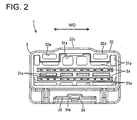
- the right side of FIG. 1 is referred to as the front and the transverse direction of FIG. 2 is referred to as the width direction.
- the connector assembly includes a male connector 1 and one or more male terminals 2 are at least partly accommodated at one or more stages, preferably at two (upper and lower) stages in a terminal-accommodating portion 31 of a male housing 3.
- the male housing 3 (predetermined or predeterminable) is formed integrally or unitarily of a synthetic resin.
- the terminal-accommodating portion 31 is arranged at an intermediate position, preferably substantially in the middle of the male housing 3 with respect to forward and backward directions FBD.
- the terminal accommodating portion 31 preferably has a substantially rectangular cross section, and the male terminals 2 are at least partly pressed or inserted into the terminal accommodating portion 31 and held or positioned therein while the opposite ends of the male terminal(s) 2 project from the opposite surfaces of the terminal accommodating portion 31.
- Each male terminal 2 preferably is made of an electrically conductive (preferably metal) material and has terminal connecting portions 2a at the opposite end portions thereof. As shown in FIG. 2, one or more, preferably a plurality of small and large bored holes 31 a are formed in the front and rear surfaces of the terminal accommodating portion 31 to make the male housing 3 lighter.
- each receptacle 32 preferably has a substantially rectangular cross section and has two bored portions 32a formed in or near its end surface.
- a (preferably substantially rectangular) locking hole 32b is formed at or near a leading end portion of each receptacle 32.
- the locking holes 32b penetrates a lateral (upper) wall of the receptacle 32 to preferably provide communication between the inside and the outside of the receptacle 32 and is engageable with a locking piece 74 of the female connector 5.
- Each reinforcing rib 32c projects from the lateral (upper) surfaces of the receptacles 32 for increasing the strength of the receptacles 32.
- Each reinforcing rib 32c has a longitudinal or extension direction substantially aligned along or parallel to the width direction WD of the male housing 3 and/or substantially parallel to the front end 32d.
- each rib 32c preferably is provided between the respective locking holes 32b and the corresponding end edge 32d of the receptacles 32.
- a front side of each rib 32c preferably is at or on or near the end edge 32d of the receptacle 32, and an intermediate part (preferably center part) of the rear side of each rib 32c preferably abuts the respective locking hole 32b.
- each rib 32c has a trapezoidal or outwardly converging shape when viewed in forward and backward directions FBD, and preferably is substantially symmetrical with the respective locking hole 32b relative to the width direction WD.
- the ribs 32c are longer than the locking holes 32b along the width direction WD of the male housing 3, i.e. have an extension or length substantially along the width direction WD (or substantially parallel to the front end 32d) greater than that of the locking holes 32b (see FIG. 3).
- the reinforcing ribs 32c each have a length that is at least about twice the width of the locking hole 32b, and preferably about four times the width of the locking hole 32b.
- each reinforcing rib 32c does not extend the full width of the receptacle 32, and preferably the length of the reinforcing rib 32c is about half the width of the receptacle 32.
- the thickness of each reinforcing rib 32c in a front to rear direction preferably is about equal to the thickness of the top wall of the receptacle 32.
- the projecting distance of each reinforcing rib 32c from the top wall of the receptacle 32 preferably is substantially less than the thickness of each reinforcing rib 32c in the front to rear direction to ensure a small profile for the housing 3.
- An insertion hole 33 is formed in the lateral (bottom) surface of the male housing 3 and penetrates the male housing 3 substantially in forward and backward directions FBD.
- a holding piece 34 is formed in or at the insertion hole 33 and is resiliently deformable in a direction intersecting the forward and backward directions FBD, preferably substantially laterally or up and down.
- An engaging projection 34a is formed at the inner or upper end of the holding piece 34.
- the male connector 1 can be mounted on a device, e.g. on a vehicle, by engaging the engaging projection 34a with an unillustrated bracket fixed to the vehicle.
- the connector assembly also includes one or more (preferably substantially identical) female connectors 5 that are connected or connectable with the male connector 1 from the front and from behind or substantially along a connecting direction CD (or the forward and backward directions FBD).
- the female connectors 5 have one or more female terminals 6 at least partly accommodated in one or more respective cavities 71 of a female housing 7.
- Each female terminal 6 is made of an electrically conductive material, preferably metal, and is connected (preferably crimped or bent or folded into connection) with a wire W.
- Each housing 7 is made integrally or unitarily preferably of a synthetic resin.
- One or more resiliently deformable locks 72 preferably are formed unitarily or integrally with the housing 7 and at least partly project into the respective cavities 71.
- the female terminals 6 deform the respective locks 72 during insertion into the cavities 71. However, the locks 72 then at least partly return resiliently to engage the terminals 6 and hold the terminals 6 in the cavities 71.
- the female connector 5 further preferably includes a retainer 8 that is formed integrally or unitarily preferably of a synthetic resin.
- the retainer 8 is at least partly mounted in or on the female housing 7 for (preferably redundantly or alternatively) retaining the female terminals 6.
- a terminal hole 73 is formed in the mating (front) wall of each cavity 71 for receiving a corresponding one of the male terminals 2.
- a locking piece 74 is formed at the lateral (upper) surface of the female housing 7 and is resiliently deformable laterally or up and down (i.e. a direction intersecting the connecting direction CD or the forward and backward directions FBD).
- a locking projection 74a projects atop or on the locking piece 74 and is at least partly engageable with the locking hole 32b when the female connector 5 is connected with the male connector 1.
- An unlocking portion 74b is formed at the rear end of the locking piece 74 and can be pressed to deform the locking piece 74 substantially laterally or outwardly or down to permit separation of the male and female connectors 1, 5.
- a guard 75 is provided above the unlocking portion 74b to prevent an operator's hand from inadvertently touching the unlocking portion 74b.
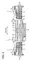
- the female connectors 5 are at least partly fit into the male connector 1 from the front and behind, as shown in FIG. 4.
- the terminal connecting portions 2a at the opposite ends of the respective male terminals 2 can at least partly enter the terminal holes 73 of the female connector 5 and can engage the female terminals 6 for electrically connecting the female terminals 6 with the male terminals 2.
- the locking pieces 74 of the female housings 7 engage the male housing 3 and deform resiliently so that the female housings 7 can at least partly enter the corresponding receptacles 32.
- the locking pieces 74 at least partly restore, preferably substantially to their original shapes, as the connection of the male and female connectors 1, 5 progresses so that the locking projections 74a engage the locking holes 32b of the male housing 3 (see FIGS. 5 and 6). In this way, the female connectors 5 preferably are locked so as not to come out of the male connector 1.
- the locking holes 32b that engage the locking pieces 74 of the female connectors 5 at least partly penetrate the receptacles 32.
- the reinforcing ribs 32c preferably are formed between the locking holes 32b and the end edges 32d of the receptacles 32.
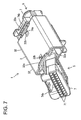
- the female housing 7 may be at least partly inserted in an improper (e.g. oblique) posture and may contact the male housing 3 near the locking hole 32b, as shown in FIG. 7.
- the reinforcing rib 32c ensures that the receptacle 32 is substantially neither deformed nor broken, and the connecting operation is not hindered.
- the rib 32c is formed only locally on or at the receptacle 32. Hence, there is less interference with other members, the weight of the receptacle 32 is lighter and the material for the receptacle 32 can be saved as compared to a case where the receptacle 32 is reinforced, for example, by being entirely thickened. Further, the enhanced strength ensures that the receptacle 32 will deform less, and therefore an engaging force between the locking hole 32b and the locking projection 74a will be greater. Furthermore, the reinforcing function of the rib 32b is enhanced by preferably making the rib 32b longer than the locking hole 32b substantially along the width direction WD of the male housing 3.
- the male connector 1 is an intermediate connector and has a terminal-accommodating portion 31 that holds or at least partly accommodates the male terminals 2 so that the opposite ends of the male terminals 2 project at the opposite sides of the terminal-accommodating portion 31.
- Receptacles 32 preferably extend at opposite sides of the terminal-accommodating portion 31 substantially along the forward and backward directions FBD and at least partly surround the male terminals 2.
- the locking holes 32b penetrate each receptacle 32 and engage the locking pieces 74 of the male connectors 5.
- the reinforcing ribs 32 are formed between the locking holes 32b and the end edges 32d of the receptacles 32.
- the invention also is applicable to a connector having a receptacle only at one side of a terminal accommodating portion and connectors of any other kind.
- the reinforcing ribs may have any size and any shape provided that they function to strengthen the receptacles formed with the locking holes.
- a plurality of reinforcing ribs may be provided in accordance with the size and shape of the housing.
- the invention is also applicable to a connector having one or more female terminal fittings.
Landscapes
- Connector Housings Or Holding Contact Members (AREA)
- Details Of Connecting Devices For Male And Female Coupling (AREA)
Applications Claiming Priority (2)
| Application Number | Priority Date | Filing Date | Title |
|---|---|---|---|
| JP2004133999A JP4285318B2 (ja) | 2004-04-28 | 2004-04-28 | コネクタ |
| JP2004133999 | 2004-04-28 |
Publications (2)
| Publication Number | Publication Date |
|---|---|
| EP1592091A1 true EP1592091A1 (de) | 2005-11-02 |
| EP1592091B1 EP1592091B1 (de) | 2007-04-04 |
Family
ID=34935843
Family Applications (1)
| Application Number | Title | Priority Date | Filing Date |
|---|---|---|---|
| EP05009255A Expired - Lifetime EP1592091B1 (de) | 2004-04-28 | 2005-04-27 | Zwischenverbinder |
Country Status (5)
| Country | Link |
|---|---|
| US (1) | US7048569B2 (de) |
| EP (1) | EP1592091B1 (de) |
| JP (1) | JP4285318B2 (de) |
| CN (1) | CN100454678C (de) |
| DE (1) | DE602005000791T2 (de) |
Cited By (4)
| Publication number | Priority date | Publication date | Assignee | Title |
|---|---|---|---|---|
| GB2432729A (en) * | 2005-11-28 | 2007-05-30 | Shao-Chieh Ting | Fixing device of a communication socket |
| DE102006048014A1 (de) * | 2006-10-09 | 2008-04-10 | Neutrik Aktiengesellschaft | XLR-Kabelsteckverbinder |
| EP1936748A1 (de) | 2006-12-19 | 2008-06-25 | Sumitomo Wiring Systems, Ltd. | Stecker und Herstellungsverfahren dafür |
| EP2949008A4 (de) * | 2013-01-22 | 2017-02-15 | Meyer Products, LLC. | Kabelbaum von fahrzeug zu winterdienstvorrichtung mit auswechselbarem verbinder |
Families Citing this family (13)
| Publication number | Priority date | Publication date | Assignee | Title |
|---|---|---|---|---|
| JP4764769B2 (ja) * | 2006-05-16 | 2011-09-07 | Idec株式会社 | 電気機器の連結構造 |
| US7682181B1 (en) * | 2008-09-09 | 2010-03-23 | Tyco Electronics Corporation | Latch securing member |
| WO2012018733A2 (en) * | 2010-08-03 | 2012-02-09 | Spx Corporation | Vehicle diagnostic, communication and signal delivery system |
| JP5287947B2 (ja) * | 2011-07-25 | 2013-09-11 | 住友電装株式会社 | コネクタ |
| JP5783468B2 (ja) * | 2012-10-29 | 2015-09-24 | 住友電装株式会社 | コネクタ |
| JP6150053B2 (ja) * | 2013-07-02 | 2017-06-21 | Smk株式会社 | コネクタ |
| US9209584B2 (en) * | 2014-03-07 | 2015-12-08 | Tyco Electronics Corporation | Electrical connector assembly |
| CN107453131B (zh) * | 2016-05-31 | 2024-04-16 | 泰科电子(上海)有限公司 | 二次锁、连接组件、连接器及连接器组件 |
| JP6415654B1 (ja) * | 2017-07-28 | 2018-10-31 | イリソ電子工業株式会社 | 電子部品 |
| FR3088491B1 (fr) * | 2018-11-12 | 2021-12-03 | Raydiall | Boitier de connecteur equipe d'un dispositif d'assurance de position de terminal de cable (tpa) ameliore |
| JP7044814B2 (ja) * | 2020-02-10 | 2022-03-30 | 矢崎総業株式会社 | 電子ユニット |
| CN113972523B (zh) * | 2020-07-22 | 2024-08-13 | 泰科电子(上海)有限公司 | 用于安装连接端子的壳体及连接器 |
| JP7837507B2 (ja) * | 2021-04-23 | 2026-03-31 | 日本圧着端子製造株式会社 | 中継コネクタ |
Citations (2)
| Publication number | Priority date | Publication date | Assignee | Title |
|---|---|---|---|---|
| US5015199A (en) * | 1988-10-28 | 1991-05-14 | Yazaki Corporation | Electric connector |
| EP0729202A2 (de) * | 1995-02-24 | 1996-08-28 | Sumitomo Wiring Systems, Ltd. | Verriegelungsmechanismus für Verbindergehäuse |
Family Cites Families (9)
| Publication number | Priority date | Publication date | Assignee | Title |
|---|---|---|---|---|
| US5507666A (en) * | 1993-12-28 | 1996-04-16 | Yazaki Corporation | Lock securing mechanism for connectors |
| JP3136909B2 (ja) | 1994-07-20 | 2001-02-19 | 住友電装株式会社 | コネクタ |
| JP3144464B2 (ja) * | 1995-11-27 | 2001-03-12 | 矢崎総業株式会社 | コネクタのロック |
| DE69737427T2 (de) * | 1996-02-09 | 2007-12-06 | Sumitomo Wiring Systems, Ltd., Yokkaichi | Steckverbinder |
| JP3625109B2 (ja) * | 1996-08-30 | 2005-03-02 | 矢崎総業株式会社 | コネクタの結合構造 |
| JP3503729B2 (ja) * | 1996-11-08 | 2004-03-08 | 住友電装株式会社 | コネクタ |
| JP3365234B2 (ja) * | 1996-12-13 | 2003-01-08 | 住友電装株式会社 | コネクタ |
| US6290527B1 (en) * | 1998-07-03 | 2001-09-18 | Nippon Telegraph And Telephone Corp. | Nippon telegraph and telephone corporation |
| JP2000077159A (ja) | 1998-08-27 | 2000-03-14 | Sumitomo Wiring Syst Ltd | コネクタ |
-
2004
- 2004-04-28 JP JP2004133999A patent/JP4285318B2/ja not_active Expired - Lifetime
-
2005
- 2005-04-27 DE DE602005000791T patent/DE602005000791T2/de not_active Expired - Lifetime
- 2005-04-27 EP EP05009255A patent/EP1592091B1/de not_active Expired - Lifetime
- 2005-04-28 US US11/117,585 patent/US7048569B2/en not_active Expired - Fee Related
- 2005-04-28 CN CNB2005100689509A patent/CN100454678C/zh not_active Expired - Fee Related
Patent Citations (2)
| Publication number | Priority date | Publication date | Assignee | Title |
|---|---|---|---|---|
| US5015199A (en) * | 1988-10-28 | 1991-05-14 | Yazaki Corporation | Electric connector |
| EP0729202A2 (de) * | 1995-02-24 | 1996-08-28 | Sumitomo Wiring Systems, Ltd. | Verriegelungsmechanismus für Verbindergehäuse |
Cited By (6)
| Publication number | Priority date | Publication date | Assignee | Title |
|---|---|---|---|---|
| GB2432729A (en) * | 2005-11-28 | 2007-05-30 | Shao-Chieh Ting | Fixing device of a communication socket |
| DE102006048014A1 (de) * | 2006-10-09 | 2008-04-10 | Neutrik Aktiengesellschaft | XLR-Kabelsteckverbinder |
| US7857643B2 (en) | 2006-10-09 | 2010-12-28 | Neutrik Aktiengesellschaft | XLR cable connector |
| EP1936748A1 (de) | 2006-12-19 | 2008-06-25 | Sumitomo Wiring Systems, Ltd. | Stecker und Herstellungsverfahren dafür |
| KR100942006B1 (ko) | 2006-12-19 | 2010-02-12 | 스미토모 덴소 가부시키가이샤 | 커넥터 및 그 형성 방법 |
| EP2949008A4 (de) * | 2013-01-22 | 2017-02-15 | Meyer Products, LLC. | Kabelbaum von fahrzeug zu winterdienstvorrichtung mit auswechselbarem verbinder |
Also Published As
| Publication number | Publication date |
|---|---|
| US20050245123A1 (en) | 2005-11-03 |
| JP4285318B2 (ja) | 2009-06-24 |
| DE602005000791D1 (de) | 2007-05-16 |
| CN100454678C (zh) | 2009-01-21 |
| JP2005317363A (ja) | 2005-11-10 |
| US7048569B2 (en) | 2006-05-23 |
| CN1691432A (zh) | 2005-11-02 |
| EP1592091B1 (de) | 2007-04-04 |
| DE602005000791T2 (de) | 2008-01-10 |
Similar Documents
| Publication | Publication Date | Title |
|---|---|---|
| EP1592091B1 (de) | Zwischenverbinder | |
| US6561834B2 (en) | Connector assembly having a latching mechanism | |
| EP1923962B1 (de) | Stecker und Vormontageverfahren dafür | |
| US5613881A (en) | Connector | |
| US6116939A (en) | Connector lock mechanism | |
| EP1587178A1 (de) | Verbinder | |
| EP1054481A1 (de) | Ein Verbinder | |
| EP1158621A2 (de) | Verbindergehäuse | |
| EP1560298B1 (de) | Getrennter Steckverbinder und Verbindereinrichtung | |
| US6769934B2 (en) | Connector and an unlocking jig therefor | |
| EP1643599B1 (de) | Ein Anschlusskontakt und ein beipassender Steckverbinder | |
| EP0954064B1 (de) | Steckverbindungspaar und Steckverbindersatz | |
| EP1548894B1 (de) | Verbinder | |
| US20030100230A1 (en) | Connector | |
| EP1351339A1 (de) | Ein verkleinerder Steckverbinder | |
| CN113571962A (zh) | 连接器以及连接器组件 | |
| US6692303B2 (en) | Terminal fitting, a connector and a method for forming a terminal fitting that facilitate insertion of the terminal fitting into the connector | |
| US7306486B2 (en) | Connector | |
| US6814618B2 (en) | Connector with resilient coupling pieces coupling locks in adjacent cavities | |
| US7001206B2 (en) | Connector and a connector assembly | |
| EP1801926B1 (de) | Verbinder und Verbinderanordnung | |
| US6835106B2 (en) | Connector, a connector assembly, a jig, and a method for withdrawing a terminal in a connector | |
| JP2502596Y2 (ja) | 電気コネクタ組立体 | |
| EP1052733A1 (de) | Elektrischer Verbinder mit einem Kontaktverriegelungselement | |
| US20040259417A1 (en) | Connector and method of molding a connector |
Legal Events
| Date | Code | Title | Description |
|---|---|---|---|
| PUAI | Public reference made under article 153(3) epc to a published international application that has entered the european phase |
Free format text: ORIGINAL CODE: 0009012 |
|
| 17P | Request for examination filed |
Effective date: 20050504 |
|
| AK | Designated contracting states |
Kind code of ref document: A1 Designated state(s): AT BE BG CH CY CZ DE DK EE ES FI FR GB GR HU IE IS IT LI LT LU MC NL PL PT RO SE SI SK TR |
|
| AX | Request for extension of the european patent |
Extension state: AL BA HR LV MK YU |
|
| AKX | Designation fees paid |
Designated state(s): DE FR |
|
| GRAP | Despatch of communication of intention to grant a patent |
Free format text: ORIGINAL CODE: EPIDOSNIGR1 |
|
| RTI1 | Title (correction) |
Free format text: AN INTERMEDIATE CONNECTOR |
|
| GRAS | Grant fee paid |
Free format text: ORIGINAL CODE: EPIDOSNIGR3 |
|
| GRAA | (expected) grant |
Free format text: ORIGINAL CODE: 0009210 |
|
| AK | Designated contracting states |
Kind code of ref document: B1 Designated state(s): DE FR |
|
| REF | Corresponds to: |
Ref document number: 602005000791 Country of ref document: DE Date of ref document: 20070516 Kind code of ref document: P |
|
| ET | Fr: translation filed | ||
| PLBE | No opposition filed within time limit |
Free format text: ORIGINAL CODE: 0009261 |
|
| STAA | Information on the status of an ep patent application or granted ep patent |
Free format text: STATUS: NO OPPOSITION FILED WITHIN TIME LIMIT |
|
| 26N | No opposition filed |
Effective date: 20080107 |
|
| REG | Reference to a national code |
Ref country code: FR Ref legal event code: PLFP Year of fee payment: 11 |
|
| PGFP | Annual fee paid to national office [announced via postgrant information from national office to epo] |
Ref country code: DE Payment date: 20150422 Year of fee payment: 11 |
|
| PGFP | Annual fee paid to national office [announced via postgrant information from national office to epo] |
Ref country code: FR Payment date: 20150408 Year of fee payment: 11 |
|
| REG | Reference to a national code |
Ref country code: DE Ref legal event code: R119 Ref document number: 602005000791 Country of ref document: DE |
|
| REG | Reference to a national code |
Ref country code: FR Ref legal event code: ST Effective date: 20161230 |
|
| PG25 | Lapsed in a contracting state [announced via postgrant information from national office to epo] |
Ref country code: FR Free format text: LAPSE BECAUSE OF NON-PAYMENT OF DUE FEES Effective date: 20160502 Ref country code: DE Free format text: LAPSE BECAUSE OF NON-PAYMENT OF DUE FEES Effective date: 20161101 |