EP1592122B1 - Procédé de commande d'onduleur - Google Patents
Procédé de commande d'onduleur Download PDFInfo
- Publication number
- EP1592122B1 EP1592122B1 EP05252614.2A EP05252614A EP1592122B1 EP 1592122 B1 EP1592122 B1 EP 1592122B1 EP 05252614 A EP05252614 A EP 05252614A EP 1592122 B1 EP1592122 B1 EP 1592122B1
- Authority
- EP
- European Patent Office
- Prior art keywords
- time
- periodic point
- power
- output power
- periodic
- Prior art date
- Legal status (The legal status is an assumption and is not a legal conclusion. Google has not performed a legal analysis and makes no representation as to the accuracy of the status listed.)
- Expired - Lifetime
Links
Images


Classifications
-
- H—ELECTRICITY
- H02—GENERATION; CONVERSION OR DISTRIBUTION OF ELECTRIC POWER
- H02M—APPARATUS FOR CONVERSION BETWEEN AC AND AC, BETWEEN AC AND DC, OR BETWEEN DC AND DC, AND FOR USE WITH MAINS OR SIMILAR POWER SUPPLY SYSTEMS; CONVERSION OF DC OR AC INPUT POWER INTO SURGE OUTPUT POWER; CONTROL OR REGULATION THEREOF
- H02M7/00—Conversion of AC power input into DC power output; Conversion of DC power input into AC power output
- H02M7/42—Conversion of DC power input into AC power output without possibility of reversal
- H02M7/44—Conversion of DC power input into AC power output without possibility of reversal by static converters
- H02M7/48—Conversion of DC power input into AC power output without possibility of reversal by static converters using discharge tubes with control electrode or semiconductor devices with control electrode
- H02M7/493—Conversion of DC power input into AC power output without possibility of reversal by static converters using discharge tubes with control electrode or semiconductor devices with control electrode the static converters being arranged for operation in parallel
-
- H—ELECTRICITY
- H02—GENERATION; CONVERSION OR DISTRIBUTION OF ELECTRIC POWER
- H02J—ELECTRIC POWER NETWORKS; CIRCUIT ARRANGEMENTS OR SYSTEMS FOR SUPPLYING OR DISTRIBUTING ELECTRIC POWER; SYSTEMS FOR STORING ELECTRIC ENERGY
- H02J3/00—Circuit arrangements for AC mains or AC distribution networks
- H02J3/38—Arrangements for feeding a single network from two or more generators or sources in parallel; Arrangements for feeding already energised networks from additional generators or sources in parallel
- H02J3/381—Dispersed generators
-
- H—ELECTRICITY
- H02—GENERATION; CONVERSION OR DISTRIBUTION OF ELECTRIC POWER
- H02J—ELECTRIC POWER NETWORKS; CIRCUIT ARRANGEMENTS OR SYSTEMS FOR SUPPLYING OR DISTRIBUTING ELECTRIC POWER; SYSTEMS FOR STORING ELECTRIC ENERGY
- H02J3/00—Circuit arrangements for AC mains or AC distribution networks
- H02J3/38—Arrangements for feeding a single network from two or more generators or sources in parallel; Arrangements for feeding already energised networks from additional generators or sources in parallel
- H02J3/46—Controlling the sharing of generated power between the generators, sources or networks
-
- H—ELECTRICITY
- H02—GENERATION; CONVERSION OR DISTRIBUTION OF ELECTRIC POWER
- H02J—ELECTRIC POWER NETWORKS; CIRCUIT ARRANGEMENTS OR SYSTEMS FOR SUPPLYING OR DISTRIBUTING ELECTRIC POWER; SYSTEMS FOR STORING ELECTRIC ENERGY
- H02J2101/00—Supply or distribution of decentralised, dispersed or local electric power generation
- H02J2101/20—Dispersed power generation using renewable energy sources
- H02J2101/22—Solar energy
- H02J2101/24—Photovoltaics
-
- H—ELECTRICITY
- H02—GENERATION; CONVERSION OR DISTRIBUTION OF ELECTRIC POWER
- H02M—APPARATUS FOR CONVERSION BETWEEN AC AND AC, BETWEEN AC AND DC, OR BETWEEN DC AND DC, AND FOR USE WITH MAINS OR SIMILAR POWER SUPPLY SYSTEMS; CONVERSION OF DC OR AC INPUT POWER INTO SURGE OUTPUT POWER; CONTROL OR REGULATION THEREOF
- H02M1/00—Details of apparatus for conversion
- H02M1/0048—Circuits or arrangements for reducing losses
-
- Y—GENERAL TAGGING OF NEW TECHNOLOGICAL DEVELOPMENTS; GENERAL TAGGING OF CROSS-SECTIONAL TECHNOLOGIES SPANNING OVER SEVERAL SECTIONS OF THE IPC; TECHNICAL SUBJECTS COVERED BY FORMER USPC CROSS-REFERENCE ART COLLECTIONS [XRACs] AND DIGESTS
- Y02—TECHNOLOGIES OR APPLICATIONS FOR MITIGATION OR ADAPTATION AGAINST CLIMATE CHANGE
- Y02B—CLIMATE CHANGE MITIGATION TECHNOLOGIES RELATED TO BUILDINGS, e.g. HOUSING, HOUSE APPLIANCES OR RELATED END-USER APPLICATIONS
- Y02B70/00—Technologies for an efficient end-user side electric power management and consumption
- Y02B70/10—Technologies improving the efficiency by using switched-mode power supplies [SMPS], i.e. efficient power electronics conversion e.g. power factor correction or reduction of losses in power supplies or efficient standby modes
-
- Y—GENERAL TAGGING OF NEW TECHNOLOGICAL DEVELOPMENTS; GENERAL TAGGING OF CROSS-SECTIONAL TECHNOLOGIES SPANNING OVER SEVERAL SECTIONS OF THE IPC; TECHNICAL SUBJECTS COVERED BY FORMER USPC CROSS-REFERENCE ART COLLECTIONS [XRACs] AND DIGESTS
- Y02—TECHNOLOGIES OR APPLICATIONS FOR MITIGATION OR ADAPTATION AGAINST CLIMATE CHANGE
- Y02E—REDUCTION OF GREENHOUSE GAS [GHG] EMISSIONS, RELATED TO ENERGY GENERATION, TRANSMISSION OR DISTRIBUTION
- Y02E10/00—Energy generation through renewable energy sources
- Y02E10/50—Photovoltaic [PV] energy
- Y02E10/56—Power conversion systems, e.g. maximum power point trackers
-
- Y—GENERAL TAGGING OF NEW TECHNOLOGICAL DEVELOPMENTS; GENERAL TAGGING OF CROSS-SECTIONAL TECHNOLOGIES SPANNING OVER SEVERAL SECTIONS OF THE IPC; TECHNICAL SUBJECTS COVERED BY FORMER USPC CROSS-REFERENCE ART COLLECTIONS [XRACs] AND DIGESTS
- Y10—TECHNICAL SUBJECTS COVERED BY FORMER USPC
- Y10S—TECHNICAL SUBJECTS COVERED BY FORMER USPC CROSS-REFERENCE ART COLLECTIONS [XRACs] AND DIGESTS
- Y10S323/00—Electricity: power supply or regulation systems
- Y10S323/906—Solar cell systems
Definitions
- the present invention relates a power system for converting DC output from a DC power source (such as a solar cell) into AC output by utilizing an inverter for power supply to an AC system.
- a DC power source such as a solar cell
- the present invention relates to a DC-AC conversion technique with the use of a plurality of inverters, for attaining efficient conversion of DC output into AC output.
- the block diagram illustrates a conventional power system.
- the power system comprises a direct current power source DC (a solar cell), a first through a third inverters PS1-PS3 connected in parallel to the power source DC, a power detector DS for detecting the output power from the power source DC, an output controller SC for controlling the inverters in accordance with the output power, and switches SW1-SW3 for connecting or disconnecting the inverters with respect to the power source DC.
- DC direct current power source
- PS1-PS3 connected in parallel to the power source DC
- a power detector DS for detecting the output power from the power source DC
- an output controller SC for controlling the inverters in accordance with the output power
- switches SW1-SW3 for connecting or disconnecting the inverters with respect to the power source DC.
- the first inverter PS1 comprises a first inverter control circuit CO1 and a first inverter circuit PC1.
- the second inverter PS2 comprises a second inverter control circuit CO2 and a second inverter circuit PC2.
- the third inverter PS3 comprises a third inverter control circuit CO3 and a third inverter circuit PC3.
- the first inverter control circuit CO1 Upon receiving a start signal from the output controller SA, the first inverter control circuit CO1 starts to operate and close the first switch SW1, so that the power outputted from the power source DC is supplied to the first inverter circuit PC1. At the same time, the control circuit CO1 actuates the inverter circuit PC1, which converts the DC voltage into AC voltage to be supplied to the system power source AC.
- the second inverter control circuit CO2 and the third inverter control circuit CO3 operate in the same manner as described above.
- the power detector DS detects the output power from the power source DC and inputs the result into the output controller SA.
- the output controller SA comprises an output power calculating unit CA and an inverter selector CH.
- the output power calculating unit CA periodically measures the output power at regular time intervals, and determines, based on the measurements, how many inverters to be actuated. Then, in accordance with the determined number of the inverters, the inverter selector CH sends a start signal to the relevant inverters.
- Fig. 7 is a timing chart for describing the operation of the conventional system.
- the output power calculating unit CA outputs a start signal for actuating one or more of the currently idle inverters.
- the additional inverter(s) needs operation delay time T1 (several tens of seconds, for example) after the start signal is inputted, until its output supply becomes stable. Due to this operational delay, the output power indicated by hatching in Fig. 7 cannot be properly converted, whereby the system power source AC fails to receive an appropriate power supply.
- JP-A-H11 (1999)-341816 (corresponding to EP0959552A ) teaches the following technique. While the current source DC (see Fig. 6 ) supplies power, this output power is measured at predetermined time intervals (each interval may be several tens of milliseconds, for example). Then, the differential quotient of the output power is calculated for the past few minutes, and it is determined whether or not the quotient tends to increase.
- the operation of the additionally actuated inverter will be stable. In this manner, since the output power does not exceed the capacity of the inverters, the output power from the power source DC can be efficiently converted.
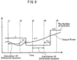
- the estimation of the output power at the next periodic point can be performed accurately when the increase of the output power is moderate, as in the case shown in Fig 8 .
- the output power may decrease sharply for the measurement time, and then may increase.
- the output power at t3 exceeds the capacity of the inverters, whereby it cannot be properly supplied to the system power source AC.
- an object of the present invention to provide an inverter controlling method capable of solving the above-described problems.
- an inverter controlling method for a power system that includes a DC power source and a plurality of inverters connected in parallel to the power source.
- the method comprises the steps of : measuring output power of the power source at a plurality of periodic points in time; calculating a moving average at each periodic point in time based on the measured output power; calculating a power difference between the moving average and the measured output power at said each periodic point in time; comparing the absolute value of the power difference at said each periodic point in time to a predetermined reference value; calculating an adjusting value at said each periodic point in time by utilizing the power difference at said each periodic point in time, wherein the adjusting value is zero if the absolute value of the power difference at said each periodic point in time is smaller than the predetermined reference value, the adjusting value is positive if the absolute value of the power difference at said each periodic point in time is not smaller than the predetermined reference value and the power difference at said each periodic point in time is positive, the adjusting value is negative if the absolute value of the
- the moving averages are calculated by averaging the output power for a predetermined period, and the regression curve is calculated based on the moving averages. Then, the output power of the next periodic point is estimated by the regression curve. In this manner, even when the output power from the power source changes sharply during the output power estimating period, the sharp change of the output power is hidden by the moving average. As a result, the estimation error of the output power at the next periodic point is considerably lessened.
- the moving average can be corrected in view of the difference between the moving average and the actual output power.
- a more accurate regression curve for estimating the output power at the next periodic point is obtained. Consequently, the estimation of the output power at the next periodic point can be performed more accurately with the use of the improved regression curve, whereby more reliable determination of the number of the inverters to be additionally actuated can be performed.
- the adjusting value is equal to the power difference multiplied by a coefficient when the absolute value of the power difference is no smaller than the reference value.
- the coefficient is equal to 1/n, where n is a natural number.
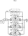
- Fig. 1 is a block diagram illustrating a power system to which an inverter controlling method according to the present invention is advantageously applied.
- elements identical or similar (in structure, function, etc.) to those shown in Fig. 6 are indicated by the same reference signs as those used in Fig 6 .
- the power system comprises a direct current power source DC (a solar cell, in the illustrated example), first to third inverters PS1 ⁇ PS3, a power detector DS, an output estimation controller SC, and first to sixth switches SW1 ⁇ SW6.
- the three inverters PS1 ⁇ PS3 are connected in parallel to the direct current power source DC for converting DC output into AC output.
- the power detector DS detects the output power from the power source DC.
- the output estimation controller SC controls the inverters PS1 ⁇ PS3 based on the detected output power.
- the switches SW1 ⁇ SW6 are operated for connecting and disconnecting the respective inverters to and from the power source DC.
- the illustrated power system uses three inverters, though the present invention is not limited to this. More than three inverters, or only two inverters, may be used for the present invention.
- the power detector DS Upon detection of the output power from the power source DC, the power detector DS sends the detected information to the output estimation controller SC.
- the output estimation controller SC comprises an output power estimation calculating unit PA and an inverter selector CH.
- the calculating unit PA periodically measures the output power at predetermined time intervals (at predetermined "periodic points"), and calculates moving averages (of the output power) at the respective periodic points.
- the moving average at a given periodic point may be an arithmetic average of the output powers measured at a predetermined number of periodic points, including the given periodic point and previous periodic points before the given periodic point.
- the moving average at periodic point t3 may be calculated by averaging the output powers measured at three consecutive periodic points t1, t2 and t3 (in a case where three pieces of measurement data are used for calculating a single moving average), and the next moving average (that is, the moving average at periodic point t4) may be calculated by averaging the output powers measured at the next three consecutive periodic points t2, t3 and t4.
- the number of pieces of measurement data used for calculating each one of the moving averages may be other than three.
- the calculating unit PA calculates a "moving average revised value" for each of the periodic points, the calculation being based on the actual output power and the calculated moving average for the periodic point. Then, based on the moving average revised values for a predetermined number of periodic points (including the current periodic point and previous periodic point(s)), the calculating unit PA calculates a regression curve used for estimating the output power at the next periodic point (for instance, when the current periodic point is point t3 in Fig. 7 , the next periodic point is point t4, which comes one cycle).
- the calculating unit PA determines how many inverters need be operated for performing proper DC-AC conversion of the output power at the next periodic point. Then, in accordance with the determination, the inverter selector CH sends a start signal (or no start signal if the estimated output power is zero, for example) to the determined number of inverters among all the inverters. For instance, when it is determined that only one inverter need be operated, the inverter selector CH may send a start signal to the first inverter PS1 only. When it is determined that two inverters need be operated, the inverter selector CH may send a start signal to the first and the second inverters PS1, PS2.
- the first inverter PS1 comprises an inverter control circuit CO1 and an inverter circuit PC1.
- the control circuit CO1 closes the first and the fourth switches SW1, SW4, so that the output power from the power source DC is supplied to the inverter circuit PC1.
- the control circuit CO1 turns on the inverter circuit PC1 to convert the direct voltage into an alternating voltage, which is supplied to the system power source AC.
- the second and the third inverters PS2-PS3, comprising an inverter control circuit CO2 or CO3 and an inverter circuit PC2 or PC3, operate in the same manner as the first inverter PS1.
- Step 100 the output power from the direct current power source DS are measured at predetermined periodic points, and the measurements are subjected to the calculation of moving averages at the respective periodic points.
- Step 300 the moving averages at the current periodic point and the predetermined number of previous periodic points are subjected to the calculation of a regression curve (which may be a quadratic or cubic curve).
- an estimated output power at the next periodic point is calculated by using the regression curve.
- the number of inverters to be operated at the next periodic point is determined in view of the estimated output power.
- the current output power from the power source DC is 180kW, and that two inverters, each having a rated power of 100kW, are operating (among four or more inverters).
- the estimation based on the regression curve indicates that the output power at the next periodic point will be 210kW, for example, the currently operating two inverters are insufficient for attaining proper voltage conversion (since their total output power is 200kW).
- the estimation indicates that the output power at the next periodic point will be 170kW, for example, the currently operating two inverters can handle the voltage conversion at the next periodic point. Thus, no additional inverters are turned on.
- Step 500 the process goes back to Step 100, and the above-described routine will be repeated.
- the regression curve is calculated based on the moving averages resulting from the output powers in a predetermined period, and the output power of the next periodic point is estimated based on the regression curve. Therefore, even when the output power changes sharply during the voltage conversion procedure, the sharp change can be smoothed by the averaging. As a result, the cause of the estimation error of the output power at the next periodic point is advantageously lessened.
- Step 100 the output power from the direct current power source DS are measured at predetermined periodic points, and the measurements are subjected to the calculation of moving averages at the respective periodic points.
- an "output power difference" between the actual output power and the moving average of the powers is calculated at each of the periodic points.
- the output power from the power source DC is measured at this point, as noted above, and the moving average for this point is calculated by averaging e.g. three output powers measured at the current point (namely, t3) and previous two points (namely, t1 and t2).
- subtracting the moving average (calculated for the point t3) from the actual output power (measured at the point t3) gives the output power difference at the point t3.
- output power differences are calculated for each of the subsequent periodic points t4, t5, and so on.
- Step 201 the absolute value of the above-defined output power difference is compared with a predetermined reference value. If the absolute value is equal to or greater than the reference value ([the absolute value] ⁇ [the reference value]), the process goes to Step 202.
- Step 202 it is determined whether the output power difference at each periodic point is positive or negative.
- the process proceeds to Step 203.
- the output power difference is negative, the process proceeds to Step 204.
- the output power difference is multiplied by a predetermined coefficient, such as 1/n (n is a natural number), to produce a positive "adjusting value.”
- Step 204 the output power difference is multiplied by a predetermined coefficient, such as 1/n (n is a natural number), to produce a negative "adjusting value.”
- Step 205 the adjusting value is added to the moving average to find a "moving average revised value" for each of the periodic points.
- the process directly goes to Step 205.
- the moving average calculated at Step 100 remains original, i.e., without being modified via Steps 202 and 203 or 204.
- Step 300 the moving average revised values at the current periodic point and the predetermined number of previous periodic points are subjected to the calculation of a regression curve (which may be a quadratic or cubic curve).
- a regression curve which may be a quadratic or cubic curve.
- an adjusting value is calculated based on the difference between the moving average and the output power, and the resultant adjusting value (including 0) is added to the moving average.
- the difference between the latest moving average and the latest output power can be reduced, whereby the output power can be approximated more accurately by the moving average.
- a more appropriate regression curve is obtained, and therefore a more reliable estimation can be made for the output power at the next periodic point.
- Figs. 4 and 5 show a flow chart illustrating an inverter control method according to a second comparative example.
- the output power from the direct current power source DS are measured at predetermined periodic points, and the measurements are subjected to the calculation of moving averages at the respective periodic points.
- the change rate (“power change rate” or "PCR”) may be calculated by the following formula: outputpower t 3 ⁇ outputpower t 2 t 3 ⁇ t 2
- the change rate may be calculated simply by subtracting the outputpower(t2) from the outputpower(t3).
- another change rate (“average change rate” or "ACR" is calculated based on the moving average at the current periodic point and the moving average at the previous periodic point.
- Step 201 it is determined whether one of the two change rates is positive and the other is negative. If YES, the process goes to Step 202. If NO (meaning that the two change rates are both positive or both negative), the process goes to Step 205.
- Step 202 it is determined whether the power change rate is positive and the average change rate is negative. If YES (a positive power change rate and a negative average change rate), the process goes to Step 203. If NO (a negative power change rate and a positive average change rate), the process goes to Step 204.
- an "output power difference" is calculated based on the output power and the moving average. Then, the absolute value of the output power difference is multiplied by a predetermined coefficient (1/n, for example, where n is a natural number), to produce a positive adjusting value.
- Step 204 as in Step 203, an "output power difference" is calculated based on the output power and the moving average. Then, the absolute value of the output power difference is multiplied by a predetermined negative coefficient (-1/n, for example, where n is a natural number), to produce a negative adjusting value.
- Step 209 the above-mentioned positive or negative adjusting value is added to the moving average at each periodic point, to produce a moving average revised value.
- Step 205 it is determined whether both the power change rate and the average change rate have the same sign (i.e., both positive or both negative). Further, if the two rates have the same sign, it is determined whether there is an intersection between the power change rate and the average change rate. If YES, the process goes to Step 206. If NO, the process goes to Step 209. In this case, the "adjusting value" (mentioned below) is regarded as zero.
- Step 206 it is determined whether the output power is greater than the moving average. If YES, the process goes to Step 207, and if NO, the process goes to Step 208.
- Step 207 an output power difference between the output power and the moving average is calculated. Then the calculated difference (>0) is multiplied by a predetermined coefficient (such as 1/n, where n is a natural number), to produce a positive adjusting value.
- a predetermined coefficient such as 1/n, where n is a natural number
- Step 208 as in Step 207, an output power difference between the output power and the moving average is calculated. Then the calculated difference ( ⁇ 0) is multiplied by a predetermined coefficient (such as 1/n, where n is a natural number), toproduce a negative adjusting value.
- a predetermined coefficient such as 1/n, where n is a natural number
- Step 209 the above-mentioned adjusting value (positive, negative or zero) is added to the moving average at each periodic point, to produce a moving average revised value.
- Step 300 a regression curve is calculated based on an appropriate number of moving average revised values (including the one at the current periodic point).
- the regression curve is used for estimating the output power at the next periodic point.
- the estimation is used for determining the number of inverters to be operated at the next periodic point.
- the power change rate and the average change rate are calculated. Further, with the use of these two change rates and the output power difference, an adjusting value for correcting the initially calculated moving average. In this manner, a more accurate regression curve is calculated, and therefore a more reliable estimation of the output power at the next periodic point can be made.
Landscapes
- Engineering & Computer Science (AREA)
- Power Engineering (AREA)
- Inverter Devices (AREA)
- Supply And Distribution Of Alternating Current (AREA)
- Control Of Voltage And Current In General (AREA)
Claims (3)
- Procédé de commande d'onduleur pour un dispositif d'alimentation qui comporte une source d'énergie à courant continu (C.C) et une pluralité d'onduleurs (PS1 à PS3) raccordés en parallèle à la source d'énergie (C.C), le procédé comprenant les étapes de :mesure de la puissance de sortie de la source d'énergie (C.C) à une pluralité d'intervalles de temps ;calcul d'une moyenne glissante à chaque période de temps sur la base de la puissance de sortie mesurée (100) ;calcul d'une différence de puissance entre la moyenne glissante et la puissance de sortie mesurée à chacun desdits intervalles de temps (201) ;comparaison de la valeur absolue de la différence de puissance à chacun desdits intervalles de temps à une valeur de référence prédéterminée (201) ;calcul d'une valeur de réglage à chacun desdits intervalles de temps en utilisant la différence de puissance à chacun desdits intervalles de temps, dans lequella valeur de réglage est nulle si la valeur absolue de la différence de puissance à chacun desdits intervalles de temps est inférieure à la valeur de référence prédéterminée,la valeur de réglage est positive si la valeur absolue de la différence de puissance à chacun desdits intervalles de temps n'est pas inférieure à la valeur de référence prédéterminée et la différence de puissance à chacun desdits intervalles de temps est positive (203),la valeur de réglage est négative si la valeur absolue de la différence de puissance à chacun desdits intervalles de temps n'est pas inférieure à la valeur de référence prédéterminée et la différence de puissance à chacun desdits intervalles de temps est négative (204) ;calcul d'une valeur actualisée de moyenne glissante à chacun desdits intervalles de temps en ajoutant la valeur de réglage à chacun desdits intervalles de temps à la moyenne glissante à chacun desdits intervalles de temps (205) ;calcul d'une courbe de régression en utilisant les valeurs actualisées de moyenne glissante à un intervalle de temps présent et des intervalles de temps passés (300) ;estimation d'une puissance de sortie à un intervalle de temps suivant sur la base de la courbe de régression (400) ; etdétermination, sur la base de la puissance de sortie estimée, du nombre d'onduleurs à activer (500).
- Procédé selon la revendication 1, dans lequel la valeur de réglage à chaque intervalle de temps est égale à la différence de puissance à chacun desdits intervalles de temps multipliée par un coefficient lorsque la valeur absolue de la différence de puissance à chacun desdits intervalles de temps n'est pas inférieure à la valeur de référence.
- Procédé selon la revendication 2, dans lequel le coefficient est égal à 1/n (n est un nombre entier).
Applications Claiming Priority (2)
| Application Number | Priority Date | Filing Date | Title |
|---|---|---|---|
| JP2004132631A JP4177284B2 (ja) | 2004-04-28 | 2004-04-28 | インバータ装置の制御方法 |
| JP2004132631 | 2004-04-28 |
Publications (3)
| Publication Number | Publication Date |
|---|---|
| EP1592122A2 EP1592122A2 (fr) | 2005-11-02 |
| EP1592122A3 EP1592122A3 (fr) | 2013-04-17 |
| EP1592122B1 true EP1592122B1 (fr) | 2016-07-27 |
Family
ID=34941052
Family Applications (1)
| Application Number | Title | Priority Date | Filing Date |
|---|---|---|---|
| EP05252614.2A Expired - Lifetime EP1592122B1 (fr) | 2004-04-28 | 2005-04-27 | Procédé de commande d'onduleur |
Country Status (4)
| Country | Link |
|---|---|
| US (1) | US7110273B2 (fr) |
| EP (1) | EP1592122B1 (fr) |
| JP (1) | JP4177284B2 (fr) |
| CN (1) | CN100588103C (fr) |
Families Citing this family (17)
| Publication number | Priority date | Publication date | Assignee | Title |
|---|---|---|---|---|
| CN100388588C (zh) * | 2006-06-01 | 2008-05-14 | 华为技术有限公司 | 一种设备供电的方法及系统 |
| JP5071342B2 (ja) * | 2008-10-23 | 2012-11-14 | 日新電機株式会社 | 信号処理装置、信号処理方法、及び電流計測装置 |
| ES2338088B8 (es) * | 2008-10-30 | 2011-08-04 | Asea Brown Boveri, S.A | Sistema y metodo de optimizacion de energia en generadores fotovoltaicos. |
| JP2011097816A (ja) * | 2009-09-30 | 2011-05-12 | Sanyo Electric Co Ltd | 発電システムおよび充放電制御装置 |
| WO2011093362A1 (fr) * | 2010-01-27 | 2011-08-04 | 三洋電機株式会社 | Procédé d'alimentation en énergie électrique, support d'enregistrement lisible par ordinateur et système de production d'énergie électrique |
| WO2011093419A1 (fr) * | 2010-01-28 | 2011-08-04 | 三洋電機株式会社 | Procédé d'alimentation électrique, support d'enregistrement lisible par un ordinateur et système de génération d'électricité |
| KR101224088B1 (ko) | 2010-10-20 | 2013-01-21 | 엘지전자 주식회사 | 인버터 제어 장치 및 제어 방법 |
| US9118213B2 (en) | 2010-11-24 | 2015-08-25 | Kohler Co. | Portal for harvesting energy from distributed electrical power sources |
| US20130088900A1 (en) * | 2011-10-10 | 2013-04-11 | Jong-Ho Park | Energy storage system and controlling method of the same |
| ES2637323T3 (es) * | 2012-03-30 | 2017-10-11 | Toshiba Mitsubishi-Electric Industrial Systems Corporation | Dispositivo de conversión de potencia |
| CN104221271B (zh) * | 2012-03-30 | 2017-10-24 | 东芝三菱电机产业系统株式会社 | 功率转换装置 |
| CN104044475B (zh) * | 2013-03-15 | 2017-07-11 | 通用电气公司 | 改进的驱动系统以及使用该驱动系统的装置 |
| JP6526421B2 (ja) * | 2015-01-09 | 2019-06-05 | シャープ株式会社 | 電力制御システム |
| CA2990612A1 (fr) * | 2015-07-02 | 2017-01-05 | Parker-Hannifin Corporation | Mini-onduleur empile en parallele pour sortie de faible puissance a haut rendement continue pendant un mode sommeil d'un onduleur principal |
| US11411533B1 (en) | 2021-10-29 | 2022-08-09 | King Fahd University Of Petroleum And Minerals | Moving linear regression based power firming filter |
| CN114400649B (zh) * | 2022-01-20 | 2025-11-14 | 深圳迈微医疗科技有限公司 | 电源电路以及电源装置 |
| CN120150237B (zh) * | 2025-05-14 | 2025-07-25 | 国网浙江省电力有限公司丽水供电公司 | 一种交直流微电网分层分布式控制方法和系统 |
Family Cites Families (10)
| Publication number | Priority date | Publication date | Assignee | Title |
|---|---|---|---|---|
| US4891744A (en) * | 1987-11-20 | 1990-01-02 | Mitsubishi Denki Kaubshiki Kaisha | Power converter control circuit |
| JPH0833211A (ja) | 1994-07-20 | 1996-02-02 | Sharp Corp | インバータ装置 |
| JPH0836433A (ja) * | 1994-07-26 | 1996-02-06 | Nissin Electric Co Ltd | システムの制御方法 |
| US5602462A (en) * | 1995-02-21 | 1997-02-11 | Best Power Technology, Incorporated | Uninterruptible power system |
| US5615129A (en) * | 1995-02-21 | 1997-03-25 | General Signal Power Systems, Inc. | Method and apparatus for adaptive and corrective determination of battery run-time in uninterruptible power systems |
| JP3540437B2 (ja) * | 1995-06-05 | 2004-07-07 | 本田技研工業株式会社 | 電池状態判別装置 |
| JP3387287B2 (ja) * | 1995-09-19 | 2003-03-17 | 日産自動車株式会社 | 回生充電制御装置 |
| JP3545203B2 (ja) * | 1998-05-22 | 2004-07-21 | 三洋電機株式会社 | インバータの運転方法及び電源システム |
| JP4293673B2 (ja) | 1999-04-20 | 2009-07-08 | 三洋電機株式会社 | 複数のインバータを有する電源システムの運転方法 |
| US6285572B1 (en) * | 1999-04-20 | 2001-09-04 | Sanyo Electric Co., Ltd. | Method of operating a power supply system having parallel-connected inverters, and power converting system |
-
2004
- 2004-04-28 JP JP2004132631A patent/JP4177284B2/ja not_active Expired - Fee Related
-
2005
- 2005-04-19 CN CN200510065970A patent/CN100588103C/zh not_active Expired - Fee Related
- 2005-04-26 US US11/114,802 patent/US7110273B2/en not_active Expired - Fee Related
- 2005-04-27 EP EP05252614.2A patent/EP1592122B1/fr not_active Expired - Lifetime
Also Published As
| Publication number | Publication date |
|---|---|
| CN1691487A (zh) | 2005-11-02 |
| CN100588103C (zh) | 2010-02-03 |
| JP4177284B2 (ja) | 2008-11-05 |
| EP1592122A3 (fr) | 2013-04-17 |
| US20050243584A1 (en) | 2005-11-03 |
| EP1592122A2 (fr) | 2005-11-02 |
| JP2005318705A (ja) | 2005-11-10 |
| US7110273B2 (en) | 2006-09-19 |
Similar Documents
| Publication | Publication Date | Title |
|---|---|---|
| EP1592122B1 (fr) | Procédé de commande d'onduleur | |
| CN100371843C (zh) | 最大电力跟踪控制装置 | |
| US9209639B2 (en) | Storage battery system and method of controlling the same | |
| US8001392B2 (en) | Battery load allocation in parallel-connected uninterruptible power supply systems | |
| JP5985775B1 (ja) | 単独運転検出装置及び単独運転検出方法 | |
| JP6384336B2 (ja) | 単独運転検出装置、制御装置、パワーコンディショナ、電源システムおよび単独運転検出方法 | |
| CN109075740B (zh) | 太阳能发电系统 | |
| EP3252908B1 (fr) | Dispositif de gestion d'énergie configuré pour déterminer les directions de montage des capteurs de courant d'un réseau électrique | |
| JP4450792B2 (ja) | インバータ装置における省電力効果表示装置 | |
| US20080239770A1 (en) | Active Network Filter | |
| EP1655167A1 (fr) | Dispositif de commande pour moteurs électriques | |
| JPH08327711A (ja) | 蓄電池残存容量計測装置 | |
| JP2003116225A (ja) | 分散電源システム | |
| JP2749502B2 (ja) | 無停電電源装置の蓄電池良否判定方法 | |
| JP7532301B2 (ja) | 発電制御システム及び発電制御方法 | |
| JPH1198857A (ja) | 多重パルス幅変調方式を用いた電力変換装置 | |
| JP2002286820A (ja) | バッテリ残量検出装置 | |
| US7617062B2 (en) | DC current calculation for fuel cell control | |
| JP2000023367A (ja) | 太陽光発電インバータ装置 | |
| EP4672540A1 (fr) | Dispositif électrique et système d'alimentation comprenant un dispositif électrique | |
| KR101027066B1 (ko) | 전류 크기 변동에 따른 상관관계 기반의 단독운전 검출 방법 | |
| JPH0984362A (ja) | Pwm制御インバータ装置及びpwm制御方法 | |
| JP2019092332A (ja) | 分散型電源システム | |
| JP2022092274A (ja) | モータ制御回路、電圧値算出方法及びプログラム | |
| JP2000002725A (ja) | インバータの入力電流検出方法 |
Legal Events
| Date | Code | Title | Description |
|---|---|---|---|
| PUAI | Public reference made under article 153(3) epc to a published international application that has entered the european phase |
Free format text: ORIGINAL CODE: 0009012 |
|
| AK | Designated contracting states |
Kind code of ref document: A2 Designated state(s): AT BE BG CH CY CZ DE DK EE ES FI FR GB GR HU IE IS IT LI LT LU MC NL PL PT RO SE SI SK TR |
|
| AX | Request for extension of the european patent |
Extension state: AL BA HR LV MK YU |
|
| PUAL | Search report despatched |
Free format text: ORIGINAL CODE: 0009013 |
|
| AK | Designated contracting states |
Kind code of ref document: A3 Designated state(s): AT BE BG CH CY CZ DE DK EE ES FI FR GB GR HU IE IS IT LI LT LU MC NL PL PT RO SE SI SK TR |
|
| AX | Request for extension of the european patent |
Extension state: AL BA HR LV MK YU |
|
| RIC1 | Information provided on ipc code assigned before grant |
Ipc: H02J 3/38 20060101ALI20130311BHEP Ipc: H02M 7/48 20070101AFI20130311BHEP |
|
| 17P | Request for examination filed |
Effective date: 20130425 |
|
| 17Q | First examination report despatched |
Effective date: 20131023 |
|
| AKX | Designation fees paid |
Designated state(s): DE FR GB IT |
|
| REG | Reference to a national code |
Ref country code: DE Ref legal event code: R079 Ref document number: 602005049809 Country of ref document: DE Free format text: PREVIOUS MAIN CLASS: H02M0007480000 Ipc: H02M0007493000 |
|
| GRAP | Despatch of communication of intention to grant a patent |
Free format text: ORIGINAL CODE: EPIDOSNIGR1 |
|
| RIC1 | Information provided on ipc code assigned before grant |
Ipc: H02J 3/38 20060101ALI20160112BHEP Ipc: H02M 7/493 20070101AFI20160112BHEP |
|
| INTG | Intention to grant announced |
Effective date: 20160209 |
|
| RAP1 | Party data changed (applicant data changed or rights of an application transferred) |
Owner name: DAIHEN CORPORATION |
|
| RIN1 | Information on inventor provided before grant (corrected) |
Inventor name: ABE, SEIYA Inventor name: KISHIDA, KOICHI |
|
| GRAS | Grant fee paid |
Free format text: ORIGINAL CODE: EPIDOSNIGR3 |
|
| GRAA | (expected) grant |
Free format text: ORIGINAL CODE: 0009210 |
|
| AK | Designated contracting states |
Kind code of ref document: B1 Designated state(s): DE FR GB IT |
|
| REG | Reference to a national code |
Ref country code: GB Ref legal event code: FG4D |
|
| REG | Reference to a national code |
Ref country code: DE Ref legal event code: R096 Ref document number: 602005049809 Country of ref document: DE |
|
| REG | Reference to a national code |
Ref country code: DE Ref legal event code: R097 Ref document number: 602005049809 Country of ref document: DE |
|
| PLBE | No opposition filed within time limit |
Free format text: ORIGINAL CODE: 0009261 |
|
| STAA | Information on the status of an ep patent application or granted ep patent |
Free format text: STATUS: NO OPPOSITION FILED WITHIN TIME LIMIT |
|
| 26N | No opposition filed |
Effective date: 20170502 |
|
| REG | Reference to a national code |
Ref country code: DE Ref legal event code: R119 Ref document number: 602005049809 Country of ref document: DE |
|
| GBPC | Gb: european patent ceased through non-payment of renewal fee |
Effective date: 20170427 |
|
| REG | Reference to a national code |
Ref country code: FR Ref legal event code: ST Effective date: 20171229 |
|
| PG25 | Lapsed in a contracting state [announced via postgrant information from national office to epo] |
Ref country code: DE Free format text: LAPSE BECAUSE OF NON-PAYMENT OF DUE FEES Effective date: 20171103 Ref country code: FR Free format text: LAPSE BECAUSE OF NON-PAYMENT OF DUE FEES Effective date: 20170502 |
|
| PG25 | Lapsed in a contracting state [announced via postgrant information from national office to epo] |
Ref country code: GB Free format text: LAPSE BECAUSE OF NON-PAYMENT OF DUE FEES Effective date: 20170427 |
|
| PG25 | Lapsed in a contracting state [announced via postgrant information from national office to epo] |
Ref country code: IT Free format text: LAPSE BECAUSE OF NON-PAYMENT OF DUE FEES Effective date: 20170427 |