EP1592355B1 - Systeme d'ablation - Google Patents
Systeme d'ablation Download PDFInfo
- Publication number
- EP1592355B1 EP1592355B1 EP04707040A EP04707040A EP1592355B1 EP 1592355 B1 EP1592355 B1 EP 1592355B1 EP 04707040 A EP04707040 A EP 04707040A EP 04707040 A EP04707040 A EP 04707040A EP 1592355 B1 EP1592355 B1 EP 1592355B1
- Authority
- EP
- European Patent Office
- Prior art keywords
- impedance
- tissue
- ablation
- tissue site
- electrode
- Prior art date
- Legal status (The legal status is an assumption and is not a legal conclusion. Google has not performed a legal analysis and makes no representation as to the accuracy of the status listed.)
- Expired - Lifetime
Links
Images




Classifications
-
- A—HUMAN NECESSITIES
- A61—MEDICAL OR VETERINARY SCIENCE; HYGIENE
- A61B—DIAGNOSIS; SURGERY; IDENTIFICATION
- A61B18/00—Surgical instruments, devices or methods for transferring non-mechanical forms of energy to or from the body
- A61B18/04—Surgical instruments, devices or methods for transferring non-mechanical forms of energy to or from the body by heating
- A61B18/12—Surgical instruments, devices or methods for transferring non-mechanical forms of energy to or from the body by heating by passing a current through the tissue to be heated, e.g. high-frequency current
- A61B18/1206—Generators therefor
-
- A—HUMAN NECESSITIES
- A61—MEDICAL OR VETERINARY SCIENCE; HYGIENE
- A61B—DIAGNOSIS; SURGERY; IDENTIFICATION
- A61B18/00—Surgical instruments, devices or methods for transferring non-mechanical forms of energy to or from the body
- A61B18/04—Surgical instruments, devices or methods for transferring non-mechanical forms of energy to or from the body by heating
- A61B18/12—Surgical instruments, devices or methods for transferring non-mechanical forms of energy to or from the body by heating by passing a current through the tissue to be heated, e.g. high-frequency current
- A61B18/14—Probes or electrodes therefor
- A61B18/1442—Probes having pivoting end effectors, e.g. forceps
-
- A—HUMAN NECESSITIES
- A61—MEDICAL OR VETERINARY SCIENCE; HYGIENE
- A61B—DIAGNOSIS; SURGERY; IDENTIFICATION
- A61B18/00—Surgical instruments, devices or methods for transferring non-mechanical forms of energy to or from the body
- A61B2018/00053—Mechanical features of the instrument of device
- A61B2018/0016—Energy applicators arranged in a two- or three dimensional array
-
- A—HUMAN NECESSITIES
- A61—MEDICAL OR VETERINARY SCIENCE; HYGIENE
- A61B—DIAGNOSIS; SURGERY; IDENTIFICATION
- A61B18/00—Surgical instruments, devices or methods for transferring non-mechanical forms of energy to or from the body
- A61B2018/00315—Surgical instruments, devices or methods for transferring non-mechanical forms of energy to or from the body for treatment of particular body parts
- A61B2018/00345—Vascular system
- A61B2018/00351—Heart
-
- A—HUMAN NECESSITIES
- A61—MEDICAL OR VETERINARY SCIENCE; HYGIENE
- A61B—DIAGNOSIS; SURGERY; IDENTIFICATION
- A61B18/00—Surgical instruments, devices or methods for transferring non-mechanical forms of energy to or from the body
- A61B2018/00315—Surgical instruments, devices or methods for transferring non-mechanical forms of energy to or from the body for treatment of particular body parts
- A61B2018/00345—Vascular system
- A61B2018/00351—Heart
- A61B2018/00363—Epicardium
-
- A—HUMAN NECESSITIES
- A61—MEDICAL OR VETERINARY SCIENCE; HYGIENE
- A61B—DIAGNOSIS; SURGERY; IDENTIFICATION
- A61B18/00—Surgical instruments, devices or methods for transferring non-mechanical forms of energy to or from the body
- A61B2018/00571—Surgical instruments, devices or methods for transferring non-mechanical forms of energy to or from the body for achieving a particular surgical effect
- A61B2018/00577—Ablation
-
- A—HUMAN NECESSITIES
- A61—MEDICAL OR VETERINARY SCIENCE; HYGIENE
- A61B—DIAGNOSIS; SURGERY; IDENTIFICATION
- A61B18/00—Surgical instruments, devices or methods for transferring non-mechanical forms of energy to or from the body
- A61B2018/00636—Sensing and controlling the application of energy
- A61B2018/00696—Controlled or regulated parameters
- A61B2018/00702—Power or energy
-
- A—HUMAN NECESSITIES
- A61—MEDICAL OR VETERINARY SCIENCE; HYGIENE
- A61B—DIAGNOSIS; SURGERY; IDENTIFICATION
- A61B18/00—Surgical instruments, devices or methods for transferring non-mechanical forms of energy to or from the body
- A61B2018/00636—Sensing and controlling the application of energy
- A61B2018/00696—Controlled or regulated parameters
- A61B2018/00761—Duration
-
- A—HUMAN NECESSITIES
- A61—MEDICAL OR VETERINARY SCIENCE; HYGIENE
- A61B—DIAGNOSIS; SURGERY; IDENTIFICATION
- A61B18/00—Surgical instruments, devices or methods for transferring non-mechanical forms of energy to or from the body
- A61B2018/00636—Sensing and controlling the application of energy
- A61B2018/00773—Sensed parameters
- A61B2018/00791—Temperature
-
- A—HUMAN NECESSITIES
- A61—MEDICAL OR VETERINARY SCIENCE; HYGIENE
- A61B—DIAGNOSIS; SURGERY; IDENTIFICATION
- A61B18/00—Surgical instruments, devices or methods for transferring non-mechanical forms of energy to or from the body
- A61B2018/00636—Sensing and controlling the application of energy
- A61B2018/00773—Sensed parameters
- A61B2018/00875—Resistance or impedance
-
- A—HUMAN NECESSITIES
- A61—MEDICAL OR VETERINARY SCIENCE; HYGIENE
- A61B—DIAGNOSIS; SURGERY; IDENTIFICATION
- A61B18/00—Surgical instruments, devices or methods for transferring non-mechanical forms of energy to or from the body
- A61B2018/00636—Sensing and controlling the application of energy
- A61B2018/00773—Sensed parameters
- A61B2018/00886—Duration
-
- A—HUMAN NECESSITIES
- A61—MEDICAL OR VETERINARY SCIENCE; HYGIENE
- A61B—DIAGNOSIS; SURGERY; IDENTIFICATION
- A61B18/00—Surgical instruments, devices or methods for transferring non-mechanical forms of energy to or from the body
- A61B18/04—Surgical instruments, devices or methods for transferring non-mechanical forms of energy to or from the body by heating
- A61B18/12—Surgical instruments, devices or methods for transferring non-mechanical forms of energy to or from the body by heating by passing a current through the tissue to be heated, e.g. high-frequency current
- A61B18/14—Probes or electrodes therefor
- A61B2018/1467—Probes or electrodes therefor using more than two electrodes on a single probe
-
- A—HUMAN NECESSITIES
- A61—MEDICAL OR VETERINARY SCIENCE; HYGIENE
- A61B—DIAGNOSIS; SURGERY; IDENTIFICATION
- A61B2218/00—Details of surgical instruments, devices or methods for transferring non-mechanical forms of energy to or from the body
- A61B2218/001—Details of surgical instruments, devices or methods for transferring non-mechanical forms of energy to or from the body having means for irrigation and/or aspiration of substances to and/or from the surgical site
- A61B2218/002—Irrigation
Definitions
- the present invention relates to tissue ablation devices generally and relates more particularly to devices adapted to ablate lines of tissue, for example for use in conjunction with an electrosurgical version of the Maze procedure.
- the Maze procedure is a surgical intervention for patients with chronic atrial fibrillation (AF) that is resistant to other medical treatments.
- the operation employs incisions in the right and left atria which divide the atria into electrically isolated portions which in turn results in an orderly passage of the depolarization wave front from the sino-atrial node (SA Node) to the atrial-ventricular node (AV Node) while preventing reentrant wave front propagation.
- SA Node sino-atrial node
- AV Node atrial-ventricular node
- the surgical Maze procedure is quite complex and is currently performed by a limited number of highly skilled cardiac surgeons in conjunction with other open-heart procedures.
- control mechanisms In conjunction with the use of electrosurgical ablation devices, various control mechanisms have been developed to control delivery of ablation energy to achieve the desired result of ablation, i.e. killing of cells at the ablation site while leaving the basic structure of the organ to be ablated intact.
- Such control systems include measurement of temperature and impedance at or adjacent to the ablation site, as are disclosed in U.S. Patent No. 5,540,681, issued to Strul, et al .
- the first approach is simply to create a series of short lesions using a contact electrode, moving it along the surface of the organ wall to be ablated to create a linear lesion. This can be accomplished either by making a series of lesions, moving the electrode between lesions or by dragging the electrode along the surface of the organ to be ablated and continuously applying ablation energy.
- the third basic approach to creation of elongated lesions is to provide a series of electrodes and arrange the series of electrodes along the desired line of lesion.
- the electrodes may be activated individually or in sequence, as disclosed in U.S. Patent No. 5,957,961 , also cited above.
- individual feedback regulation of ablated energy applied via the electrodes may also be employed.
- the present invention is believed useful in conjunction with all three approaches
- the present invention is directed towards an improved system as defined in claim 1 for creating lesions and assessing their completeness or transmurality.
- the preferred embodiments of the invention are directed toward an improved system for creating elongated lines of lesion and assessing their completeness or transmurality.
- the apparatus for producing the lesions is an electrosurgical device, in particular a saline-irrigated bipolar electrosurgical forceps.
- the mechanism for assessing lesion transmurality provided by the present invention is believed useful in other contexts, including unipolar radio-frequency (RF) ablation and RF ablation using catheters or hand-held probes.
- RF radio-frequency
- the mechanism for assessing transmurality may also be of value in the context of other types of ablation systems, particularly those which ablation occurs in conjunction with an induced rise in tissue temperature such as those applying ablation energy in the form of microwave radiation, light (laser ablation) or heat (thermal ablation).
- assessment of transmurality of a lesion is accomplished by monitoring the impedance of the tissue to be ablated.
- tissue impedance first falls and then reaches a stable plateau, during which portion the lesion is completed. Thereafter, the impedance rises.
- the present invention detects completeness of a lesion in response to the measured impedance remaining at a stable level for a desired period of time, hereafter referred to as an impedance plateau.
- measurement of impedance may be done using the ablation electrodes or may be done using dedicated electrodes adjacent to the ablation electrodes.
- impedance measurement would typically be accomplished by means of a dedicated set of impedance measurement electrodes.
- the invention is believed most valuable in conjunction with an ablation device having multiple, individually activatable electrodes or electrode pairs to be arranged along a desired line of lesion.
- the mechanism for determining transmurality of lesions adjacent individual electrodes or pairs may be used to deactivate individual electrodes or electrode pairs, when the lesions in tissue adjacent these individual electrodes or electrode pairs are complete. This allows the creation of an essentially uniform lesion along the line of electrodes or electrode pairs, regardless of differences in tissue thickness adjacent the individual electrodes or electrode pairs.
- the invention is also believed useful in conjunction with assessment of transmurality of lesions produced by devices having only a single electrode or single electrode pair. Similar considerations apply to the use of the present invention in the contexts of other types of ablation as listed above.
- RF power delivery can also be controlled in order to assess lesion transmurality.
- the ablation will commence at a first power level and will be increased to a second power level as certain conditions are satisfied.
- the power level can also be increased from the second power level to a third power level as certain conditions are satisfied.
- the increase in power level can continue in the same stepwise manner, increasing the power level from an N power level to an n+1 power level until a set of conditions are met that indicates that transmurality has been achieved and/or that the power should be turned off.
- Conditions for an increase in power level can include one or more of the detection of a plateau in impedance or the achievement of a maximum permitted time for that power level.
- Conditions indicating that transmurality has been achieved can include one of: the lack of change in detected impedance in response to the change in power level or the detection of a rapid rise in impedance. If transmurality is detected by satisfying one of these conditions, the power is turned off and the ablation is complete. If a condition indicating that transmurality has been achieved is not detected, such as a drop in detected impedance in response to the change to the higher power level, ablation is continued at the higher power level until the conditions are met for again increasing the power level or conditions indicating transmurality are met. This process may be continued in a stepwise fashion until the conditions for detection of transmurality are detected, a predetermined number of plateaus in impedance have been detected or until an overall maximum time for the ablation is achieved.
- FIG. 1 is a plan view of a bipolar, saline irrigated electrosurgical hemostat of a type that may be employed in conjunction with the present invention.
- the hemostat is provided with elongated handles 11 and 12 and a lock mechanism 14, similar to a conventional surgical hemostat.
- the handles are connected to one another by pivot or hinge 16, and continue distally in the form of elongated jaws 18 and 19.
- Jaws 18 and 19 carry an elongated electrode or series of electrodes 24, 25, respectively, to which ablation energy, e.g. RF energy is applied by means of conductors 21 and 22.
- the electrodes are adapted to be irrigated by a saline solution or other conductive fluid along their length, provided via inlet tubes 20 and 23.
- tissue to be ablated is compressed between the jaws, and RF energy is applied between the electrode or electrode sets 24 and 25, as generally described in U.S. Patent No.: 6,096,037 issued to Mulier et al .
- FIG 2a shows a first embodiment of an electrode arrangement for a hemostat generally as illustrated in Figure 1 .
- Illustrated components correspond to identically numbered components in Figure 1 .
- electrodes 24 and 25 take the form of elongated coil electrodes 30 and 32, mounted around porous tubes 34 and 36, through which saline or other conductive fluid is delivered.
- the arrangement of the electrodes may also be reversed, for example placing coils 30 and 32 within elongated porous tubes 34 and 36, to accomplish a similar result.
- any other arrangement for providing an elongated electrode and delivery of saline solution along the length thereof may be substituted.
- the particular configuration of the electrode is not critical to the present invention. For example, irrigated electrodes corresponding to those described in U.S.
- Patent No. 6,096,037 issued to Mulier, et al ., U.S. Patent No. 5,876,398 issued to Mulier, et al ., or U.S. Patent No. 5,913,856 issued to Chia, et al . may also be substituted.
- the electrode system as illustrated in Figure 2a is a bipolar system, the invention may also be employed in conjunction with unipolar electrodes and/or in the form of a probe or a catheter. In some embodiments, irrigation of the electrodes may be omitted.
- FIG 2b illustrates an alternative embodiment of an electrode system for a hemostat generally as illustrated in Figure 1 .
- the electrode pairs comprise coil electrodes 40 and 42, 44 and 46, 48 and 50, 52 and 54, and 56 and 58.
- other pairings of electrodes might also be substituted, for example, pairing electrodes 40 and 44, electrodes 48 and 52 or the like.
- the electrode pairs are mounted around porous plastic tubes 60 and 62 through which saline or other electrically conductive fluid is delivered.
- the arrangement of these electrodes may readily be reversed, placing the electrodes within the lumen of plastic tube 60 or 62 and any other arrangement providing multiple, irrigated electrodes may also be substituted.
- unipolar electrodes might be substituted for the multiple bipolar pairs as illustrated and/or the invention may be practiced in conjunction with a multi-electrode probe or catheter. While the particular arrangement of electrodes is not believed critical to practicing the present invention, it is believed that the invention may be most beneficially practiced in conjunction with a set of linearly arranged bipolar electrode pairs as illustrated in Figure 2b .
- the hemostat is arranged so that the tissue to be ablated is located between the jaws 18 and 19, and pressure is applied in order to compress the tissue slightly between the jaws to ensure good electrical contact.
- All electrode pairs may be activated individually and may be individually deactivated when the lesions between the individual electrode pairs are completely transmural. Alternatively, electrode pairs could be activated sequentially, with one pair deactivated upon a detection of a complete lesion between the electrode pair, followed by activation of the next sequential electrode pair.
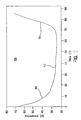
- Figure 3 is a graph illustrating measured impedance versus time across tissue located between the electrodes of an irrigated bipolar hemostat as illustrated in Figure 1 .
- Figure 3 illustrates the drop in impedance followed by an impedance plateau, ultimately followed by an impedance rise.
- the impedance plateau is the primary indicator of transmurality employed by the present invention.
- tissue is desiccated or as steam or microbubbles forms in the tissue, an impedance rise will generally occur.
- the detection of this rise in impedance is employed as an alternative or mechanism for assessing transmurality and/or as a safety mechanism in order to assure shut off of the ablation electrodes before excessive physical damage to the tissue results.
- FIG 4 is a functional block diagram illustrating one embodiment of an RF generator system for use in conjunction with the present invention.
- separately controllable RF outputs are provided for individual ablation electrodes or electrode pairs on an associated RF ablation device, for example as in Figure 2B .
- the RF generator could of course also be used with ablation devices having only a single electrode or electrode pair as in Figure 2A .
- the generator corresponds generally to that described in conjunction with Figure 14 of the '961 patent issued to Maguire, et al., cited above.
- the RF generator disclosed in the '961 patent provides feedback control of RF power based upon either measured power (constant power) or temperature.
- the present invention is somewhat easier to implement in conjunction with the constant power mode, but may also be adapted to a temperature-regulated mode or to other feedback power regulation mechanism.
- Display 804 and controls 802 are connected to a digital microprocessor 800, which permits interface between the user and the remainder of the electrical components of the system.
- Microprocessor 800 operates under control of stored programming defining its operation including programming controlling its operation according to the present invention, as discussed in more detail below.
- Microprocessor 800 provides control outputs to and receives input signals from the remaining circuitry via address/data bus 806.
- the microprocessor 800 provides for monitoring of power, current, voltage, impedance and temperature. As necessary, the microprocessor will provide this information to the display 804. Additionally, the microprocessor 800 permits the user to select the control mode (either temperature or power) and to input the power set point, temperature set point, and a timer set point to the system.
- the primary source of power for the radio-frequency generator may be a 12 V battery rated at 7.2 ampere-hours.
- the device may be AC powered.
- a back-up battery (not shown) such as a lithium cell may also be provided to provide sufficient power to the microprocessor 260 to maintain desired memory functions when the main power is shut off.
- the power supply system as illustrated includes a desired number "M” of individually controllable RF power supplies and receives temperature inputs from a desired number "N” of temperature sensing devices in the ablation device, illustrated schematically at 838 and receives temperature inputs from a desired number "M” of impedance monitoring circuits.
- Each RF power supply includes a transformer (822, 824, 826), a power control circuit (810, 812, 814) and a power measurement circuit (816, 818, 820).
- a crystal-locked radio-frequency oscillator 264 generates the switching pulses, which drive both the power transformers (822, 824, 826) and the power controllers (810, 812, 814).
- Power controllers (810, 812, 814) may be analog controllers which operate by pulse-width modulation by comparing a power set point signal from microprocessor 800 with an actual power signal generated by a power measurement circuit (816, 818, 820), which may, for example, include a torroidal transformer coupled to the power output from the associated transformer (822, 824, 826).
- the power measurement circuits (816, 818, 820) multiply the output current and voltage and provide the resulting actual power signal to both the power controllers (810, 812, 814) and the microprocessor 800.
- the RF power output of the transformers (822, 824, 826) is provided to inter face board 808, and thereby is provided to the ablation electrode or electrodes on the ablation device 838.
- Separate analog comparator circuits may also be provided for monitoring the output of the power measurement circuits (816, 818, 820), in order to shutoff current to the output transformers (822, 824, 826) if the power exceeds a limit, typically 55 watts.
- Power transformers (822, 824, 826) may include center taps, which receive the outputs of the power controllers (810, 812, 814). Secondary windings of the transformers (822, 824, 826) may provide for continuous monitoring of the applied voltage in order to permit the power calculations by power measurement circuits (816, 818,820).
- the illustrated power RF generator system employs software controlled temperature processing, accomplished by micro processor 800, which receives the "N" temperature input signals from temperature measurement circuits (828, 830, 832), each of which are coupled to a corresponding temperature sensor in ablation device 838 by means of an electrical connector, illustrated schematically at 836 and interface circuit 834. If programmed to operate in the temperature controlled mode, processor 800 receives the "N" temperature signals and, based upon the indicated temperatures, defines power set points for each of the power control circuits (810, 812, 814), which in the manner described above control the power levels applied to electrodes on the catheter through interface 834. Processor 800 may also selectively enable or disable any of the "M" provided RF power sup plies, in response to external control signals from controls 802 or in response to detected anomalous temperature conditions.
- the apparatus of Figure 4 includes multiple impedance monitoring circuits ZM1, ZM2...ZMM (842, 844 and 846 respectively), which may operate as described in U.S. Patent No. 5,733,281, issued to Nardella . to measure an impedance between electrodes on a RF ablation device. Impedance may be measured between the ablation electrodes or between electrodes located adjacent the ablation electrodes, as described in U.S. Patent No. 5,558,671 .
- a determination of transmurality is made in response to a detection of a series of impedance measurements that are relatively constant, over a desired period of time or over a defined number of successive impedance measurements.
- an abrupt rise in impedance may also be employed to terminate delivery of ablation energy.
- the microprocessor may employ voltage and current measurements of impedance measurement signals generated by the power transformers (822, 824, 826) to derive impedance and may use such derived impedance values in conjunction with the present invention.
- impedance measurement signals generated by the power transformers (822, 824, 826)
- the microprocessor may employ voltage and current measurements of impedance measurement signals generated by the power transformers (822, 824, 826) to derive impedance and may use such derived impedance values in conjunction with the present invention.
- measurement of impedance in this fashion is disclosed in US Patent No. 5,540;681, issued to Strul, et al , cited above or U.S. Patent No. 5,573,533, issued to Strul .
- Figure 5A is a functional flow chart illustrating the operation of a device as in Figure 4 , according to the present invention.
- the flow chart of Figure 5A illustrates operation of the device of Figure 4 to control provision of RF energy to an individual electrode or electrode pair.
- the control methodology of Figure 5A would be applied to each electrode or electrode pair individually, as discussed in more detail below in conjunction with Figures 7 and 8 .
- the flow chart of Figure 5A illustrates a method of assessing transmurality and terminating delivery of ablation energy to an electrode or an electrode pair responsive to detection of a plateau in impedance in conjunction with a detected drop in impedance. Following the detection of a plateau in conjunction with the required impedance drop, the device waits a defined time period and then terminates the application of ablation energy to the associated electrode pair. Measurement of impedance in tissue associated with the electrode pair may be made using the ablation electrodes themselves or electrodes located in proximity to the ablation electrodes, for example as described in the Yates '671 patent, mentioned above.
- the microprocessor 800 ( Fig. 4 ) initiates delivery of ablation energy at 201 and causes the impedance measurement circuitry associated with the electrode or electrode pair being evaluated, or derives impedance based on applied voltage and current as discussed above, to acquire a base line or initial impedance Z i , which may be, for example the maximum impedance during the first three seconds of ablation.
- a base line or initial impedance Z i which may be, for example the maximum impedance during the first three seconds of ablation.
- Z i which may be, for example the maximum impedance during the first three seconds of ablation.
- the microprocessor thereafter acquires a current impedance value Z n at 206.
- n is incremented at 208 and compared with a predefined value "a" at 210 to determine whether a sufficient number of impedances have been measured in order to calculate the rate of change of impedance (d2/dt).
- dZ/dt may be calculated by taking the measured impedance Z n and comparing it to the preceding measured impedance Z n-1 , in which case n would have to be greater or equal to 2 in order for dZ/dt to be calculated.
- dZ/dt may be calculated by taking the measured impedance Z n and comparing it to the previously measured impedance Z n-2 , in which case n would have to be greater or equal to 3 in order for dZ/dt to be calculated. If "n" is less than "a" at 210, the microprocessor waits an impedance sampling interval ⁇ t 1 which may be, for example, 0.2 seconds, and then triggers an impedance measurement again at 206. This process continues until there are a sufficient number of collected impedance measurements to calculate dZ/dt at 212.
- ⁇ t 1 may be, for example, 0.2 seconds
- the microprocessor 800 employs the stored impedance measurements to calculate dZ/dt, which may, for example, be calculated as equal to (1/(2 ⁇ t 1 )) (Z n -Z n-2 ).
- n is employed to assess whether or not an impedance plateau has been reached at 214.
- the microprocessor checks at 214 to determine whether
- an appropriate value of "b” might be 1.3.
- the value of "b” may have to be adjusted.
- Other power control modes, e.g. temperature controlled would similarly require adjustment of this parameter.
- the value of "b" and other parameters employed to determine transmurality using the present invention can be determined empirically in the laboratory by applying the specific electrode set and RF generation system in question to test specimens, reading impedances at defined sample intervals and using the results to optimize the various parameters.
- the count "m” is incremented at 216 and m is compared to a third constant "c" which sets forth the defined number of low value
- c may be 6 - 12.
- n values must be less than "b” may be substituted, e.g. 8 of 12, or the like.
- the microprocessor waits the impedance sampling interval ⁇ t 1 at 220 and continues to acquire successive impedance measurements until sufficient number of sequential low values of
- the microprocessor When both of these criteria have been met at 220, the microprocessor than waits for an additional time interval ⁇ t2 to assure completeness of the lesion at 222 and thereafter terminates the provision of ablation energy to the specific electrode pair being regulated at 224 and the ablation process with regard to that electrode or electrode pair is terminated at 226.
- Figure 5B illustrates an additional set of operations for implementing a transmurality measurement method generally as in Figure 5A .
- the operations of Figure 5B may either be a substituted for step 222 of Figure 5A or alternatively may be performed before or after step 222.
- the microprocessor increases the power to the electrodes under consideration slightly at 228 and sets a timer at 230.
- the microprocessor then causes the impedance measurement apparatus associated with the electrodes under consideration to measure current impedance at 234 and calculate
- the microprocessor In the event that the value of
- the value of "e” may be equal to "b” or may be different. If the value of
- the microprocessor waits the impedance sampling interval ⁇ t1 at 238 and continues to collect impedance values and calculate
- Figure 6 illustrates a second basic approach to assessment of transmurality and control of delivery of ablation energy to an electrode pair.
- the procedure defined by the flow chart of Figure 6 it should be understood to be employed in conjunction with an impedance measurement circuit with a single electrode pair, which procedure would be repeated for other electrodes or electrode pairs, if present.
- the value of "n" is set to Zero at 302 and a timer is initiated at 304, used to determine that a sufficient amount of time has passed prior to termination of ablation.
- ten seconds may be an appropriate time interval for the timer initiated at 304.
- the microprocessor than measures the current impedance Z n at 310 increments the value of "n" at 310 and checks at 314 to determine whether an adequate number of impedance measurements have been accumulated to make a calculation of dZ/dt at 314, in the same fashion as discussed above in conjunction with Figures 5a and 5b . If an inadequate number of samples have been collected, the microprocessor waits the impedance sampling interval ⁇ t at 308 and continues to collect impedance measurements until an adequate number "a" of measurement have been collected. In the specific example presented, "a" may be set equal to 5 and ⁇ t may be .2 seconds.
- the microprocessor calculates the value of dZ/dt n and
- filtered or average impedance values Z a may be employed to calculate dZ/dt and
- the microprocessor may calculate the value of dZ/dt according to the following method.
- the microprocessor may employ a 5 point moving average filter to produce an average impedance value Z a , which is equal to (Z n + Z n-1 + Z n-2 + Z n-3 + Z n-4 )/5.
- n may be calculated in the same fashion as in conjunction with the flow charts of Figure 5A and 5B discussed above, substituting the averaged impedance values Z a for the individual impedance values Z n as employed in the previous flow charts.
- microprocessor 308 may attempt to determine whether an impedance plateau has been reached employing the following method. The microprocessor reviews the preceding 15 measurements of dZ/dt n , and
- the microprocessor checks at 319 to determine whether an adequate period of time has elapsed since ablation was initiated, if not, the microprocessor waits for the impedance sampling interval ⁇ t at 312 and continues to measure impedances and calculate values of dZ/dt according to the above described method until both a plateau is present and the defined time period "b" has elapsed at 319. After the required time period at "b" at 319 has elapsed, delivery of ablation energy to the associated electrode or electrode pair is terminated at 322 and the ablation process ceases at 324 as to that electrode pair.
- the microprocessor may nonetheless safely terminate provision of ablation energy to the electrode pair under consideration in response to a detected rapid rise in impedance, which normally follows the impedance plateau.
- the processor checks to see whether the required minimal time period has elapsed at 319, and if so, terminates ablation at 322 as discussed above. If the minimal time interval "b" has not elapsed, the microprocessor continues to acquire measurements of impedance and continues to calculate values of dZ/dt and
- Figure 7 is a function flow chart illustrating the over-all operation of the device in conjunction with a multi electrode or multi electrode pair ablation apparatus.
- all the electrodes are activated simultaneously and individual electrodes or electrode pairs are deactivated in response to impedance measurements associated with the electrode pair indicating that the lesion formed between that electrode pair is completely transmural.
- the ablation system works as follows.
- all electrodes 1-x are activated at 402, meaning that ablation energy is provided to all electrodes and electrode pairs.
- the microprocessor then checks the value of dZ/dt and/or
- the microprocessor checks using any of the mechanisms described above to determine whether an impedance plateau has been reached or, in the event that additional criteria for shut off of ablation energy are provided, to see whether any of these additional criteria are reached. If so, the electrode being examined is deactivated at 410 by ceasing the delivery of ablation energy to the electrode or electrode pair.
- the microprocessor checks the value of dZ/dt and/or
- Figure 8 illustrates a functional flow chart of overall operation of a device in which a multi-electrode or multi-electrode pair ablation apparatus is employed, as in Figure 7 .
- electrodes or electrode pairs are activated initially and sequentially.
- the microprocessor activates delivery of ablation energy to the first electrode at 502, checks dZ/dt and/or
- the microprocessor After deactivation of an electrode at 510, the microprocessor checks to determine whether all electrodes have been activated and deactivated at 512, if not, the microprocessor then activates the next electrode at 506 and initiates delivery of ablation energy to that electrode. This process continues until the last electrode has been deactivated at 512, following which the microprocessor determines that the ablation process is complete at 514 and the ablation process is stopped at 516.
- the overall operational methodology of Figure 7 is believed to be desirable in that it allows for a more rapid completion of an ablation procedure.
- the overall operational method is described in Figure 8 has the advantage that it may allow the use of a somewhat simplified generator because that multiple, separate impedance measurement circuits, power control circuits, and the like need not be provided for each electrode or electrode pair.
- a simple switching mechanism may be used in conjunction with only a single RF generator and impedance measurement circuit to successively apply energy to each electrode and to monitor impedance according to the invention.
- Figures 9-12 show yet another aspect of the invention in which RF power delivery can also be controlled in order to assist in the assessment of lesion transmurality.
- the ablation commences at a first power level and is then increased to a second power level as certain conditions are satisfied.
- the power level can also be increased from the second power level to a third power level and in the same stepwise manner, increasing the power level from an N power level to an n+1 power level until a set of conditions are met that indicates that transmurality has been achieved and/or that the power should be turned off.
- an initial power level P 0 can be selected in the range of about 10 to 25 watts.
- the power level can then be rapidly increased to a second power level P 1 in an increment in the range of about 3 to 10 watts at a rate of at least about 0.5 watts/second.
- Subsequent power levels P 2 , P 3 , etc. can be similarly achieved.
- a maximum permitted power in the range of about 25-50 watts can also be selected to ensure that the power level is not raised beyond safe limits.
- Typical power levels could be an initial power level P 0 of about 25 watts and a second power level P 1 of about 30 watts.
- Power levels P2, P3, etc. could be increased in similar increments until a maximum power level of about 40 watts was achieved.
- an initial selected power level P 0 is either maintained or increased to a second power level in response to changes in the detected impedance occurring during the ablation.
- the initial detected impedance Z 0 drops initially as ablation proceeds.
- each of Figures 9-12 shows exemplary alternative responses of a system according to the invention as differing impedance conditions are detected.
- the power level remains the same during the entire ablation procedure because a detected rapid rise in impedance dZ/dt rise is detected without first detecting a plateau.
- One condition indicating that transmurality has been achieved is a rapid rise in impedance such as that shown in Figure 9 .
- Conditions for an increase in power level can include one or more of: the detection of a plateau in impedance or a slow rise in impedance or the achievement of a maximum permitted time for that power level.
- Conditions indicating that transmurality has been achieved can include one of: the lack of change in detected impedance in response to the change in power level or the detection of a rapid rise in impedance.
- Figure 10 shows the detection of a plateau in the impedance curve at dZ/dt 1 , which triggers a rapid increase in power level from P 0 to P 1 .
- the increase in power level causes a drop in impedance and therefore the ablation is continued at the second power level P 1 until the detected impedance indicates a rapid rise dZ/dt rise .
- the power is turned off and the ablation for the lesion is completed.
- ablation at the power level P 0 may be continued for a maximum pre-selected period of time followed by an increase in power level to power level P 1 .
- a time in the range of about 3 to 20 seconds, or more preferably about 8 seconds could be selected as the maximum duration for ablation at a particular power level.
- Figure 11 shows the detection of a plateau in impedance at dZ/dt 1 which triggers an increase in power level from P 0 to P 1 . Because the impedance drops in response to the increased power level, ablation continues at the second power level P 1 until a second plateau in impedance is detected at dZ/dt 2 . The detection of the second impedance plateau triggers a second increase in power level, from P 1 to P 2 . Because the impedance drops in response to the increase in power level, ablation is continued at the third power level P 2 until a rapid rise in impedance is detected at dZ/dt rise . Upon detection of the rapid impedance rise, the power is turned off and the ablation for the lesion is completed.
- Figure 12 shows the detection of a plateau in impedance at dZ/dt 1 , which triggers an increase in power level from P 0 to P 1 . Because the impedance drops in response to the increased power level, ablation continues at the second power level P 1 until a second plateau is detected at dZ/dt 2 . The detection of the second plateau triggers a second increase in the power level from P 1 to P 2 . Because the impedance does not drop in response to the increase in power level from P 1 to P 2 , the continued plateau is verified by impedance measurement at dZ/dt 3 and the ablation is immediately terminated.
- FIGs 9-12 illustrates successful termination of ablation by detecting impedance that is characteristic of achievement of transmurality.
- the ablation can still be terminated if the total time for the ablation exceeds a predetermined limit.
- a total limit on ablation to form the lesion could take about 30 to 60 seconds, and preferably about 40 seconds.
- ablation could also be stopped upon reaching a maximum power level or after the completion of a predetermined number of power level increases.
Landscapes
- Health & Medical Sciences (AREA)
- Surgery (AREA)
- Engineering & Computer Science (AREA)
- Life Sciences & Earth Sciences (AREA)
- Biomedical Technology (AREA)
- Molecular Biology (AREA)
- Nuclear Medicine, Radiotherapy & Molecular Imaging (AREA)
- Plasma & Fusion (AREA)
- Physics & Mathematics (AREA)
- Heart & Thoracic Surgery (AREA)
- Medical Informatics (AREA)
- Otolaryngology (AREA)
- Animal Behavior & Ethology (AREA)
- General Health & Medical Sciences (AREA)
- Public Health (AREA)
- Veterinary Medicine (AREA)
- Surgical Instruments (AREA)
- Developing Agents For Electrophotography (AREA)
Claims (18)
- Système d'ablation, comportant:des moyens (21, 22, 24, 35) pour appliquer une énergie d'ablation à un premier site de tissu ;des moyens (800) surveillant l'impédance de tissu du premier site de tissu ; etdes moyens (800) sensibles à l'impédance de tissu surveillée dans le premier site de tissu restant constante sur une période de temps prédéterminée ou sur un nombre donné de mesures d'impédance discrètes successives pendant lequel l'ablation du premier site de tissu est réalisée pour augmenter l'application de l'énergie d'ablation au premier site de tissu.
- Système selon la revendication 1, dans lequel les moyens pour appliquer une énergie d'ablation au premier site de tissu comportent une première électrode RF.
- Système selon la revendication 2, dans lequel les moyens pour surveiller une impédance de tissu du premier site de tissu comportent la première électrode RF.
- Système selon la revendication 1, dans lequel les moyens pour surveiller une impédance de tissu du premier site de tissu comportent des moyens pour surveiller des mesures de tension et de courant afin de dériver l'impédance.
- Système selon la revendication 1, dans lequel les moyens pour surveiller une impédance de tissu du premier site de tissu comportent des électrodes de surveillance dédiées.
- Système selon la revendication 1, dans lequel les moyens pour appliquer une énergie RF au premier site de tissu comportent une première électrode RF irriguée.
- Système selon l'une quelconque des revendications 1 à 6, dans lequel les moyens pour appliquer une énergie d'ablation au premier site de tissu comportent des moyens pour augmenter l'application d'une énergie d'ablation en réponse à une série d'impédances de tissu surveillées qui ont un degré de changement acceptable.
- Système selon l'une quelconque des revendications 1 à 6, dans lequel les moyens pour appliquer une énergie d'ablation au premier site de tissu comportent des moyens pour augmenter l'application d'une énergie d'ablation en réponse à une série d'impédances de tissu surveillées qui ont une vitesse de changement acceptable.
- Système selon l'une quelconque des revendications précédentes, comportant en outre :des moyens pour appliquer une énergie d'ablation à un second site de tissu ;des moyens pour surveiller une impédance de tissu du second site de tissu ; etdes moyens sensibles à l'impédance de tissu surveillée dans le second site de tissu restant constante sur une période de temps prédéterminée ou sur un nombre donné de mesures d'impédance discrètes successives, pour augmenter l'application d'énergie d'ablation au second site de tissu.
- Système selon la revendication 9, dans lequel les moyens pour appliquer une énergie d'ablation au second site de tissu comportent une seconde électrode RF.
- Système selon la revendication 10, dans lequel les moyens pour surveiller une impédance du second site de tissu comportent la seconde électrode RF.
- Système selon la revendication 10, dans lequel les moyens pour surveiller une impédance de tissu du second site de tissu comportent des moyens pour surveiller des mesures de tension et de courant afin de dériver l'impédance.
- Système selon la revendication 9, dans lequel les moyens pour surveiller une impédance de tissu du second site de tissu comportent des moyens pour surveiller une impédance en utilisant des électrodes de surveillance dédiées.
- Système selon la revendication 9, dans lequel les moyens pour appliquer une énergie RF au second site de tissu comportent une seconde électrode RF irriguée.
- Système selon l'une quelconque des revendications 9 à 14, dans lequel les moyens pour appliquer une énergie d'ablation au second site de tissu comportent des moyens pour augmenter l'application d'une énergie d'ablation en réponse à une série d'impédances surveillées qui ont un degré de changement acceptable.
- Système selon l'une quelconque des revendications 9 à 14, dans lequel les moyens pour appliquer une énergie d'ablation au second tissu comportent des moyens pour augmenter l'application d'une énergie d'ablation en réponse à une série d'impédances de tissu surveillées qui ont une vitesse de changement acceptable.
- Système selon l'une quelconque des revendications précédentes, comportant en outre :des moyens sensibles à la survenue d'une augmentation de l'impédance de tissu dans le premier site de tissu pour modifier une application d'énergie d'ablation au premier site de tissu.
- Système selon la revendication 17 lorsqu'elle dépend de la revendication 9, comportant en outre :des moyens sensibles à la survenue d'une augmentation d'impédance dans le second site de tissu pour modifier une application d'énergie d'ablation au second site de tissu.
Applications Claiming Priority (3)
| Application Number | Priority Date | Filing Date | Title |
|---|---|---|---|
| US10/364,553 US6989010B2 (en) | 2001-04-26 | 2003-02-11 | Ablation system and method of use |
| US364553 | 2003-02-11 | ||
| PCT/US2004/002739 WO2004071316A2 (fr) | 2003-02-11 | 2004-01-30 | Systeme d'ablation et son procede d'utilisation |
Publications (2)
| Publication Number | Publication Date |
|---|---|
| EP1592355A1 EP1592355A1 (fr) | 2005-11-09 |
| EP1592355B1 true EP1592355B1 (fr) | 2008-07-02 |
Family
ID=32867975
Family Applications (1)
| Application Number | Title | Priority Date | Filing Date |
|---|---|---|---|
| EP04707040A Expired - Lifetime EP1592355B1 (fr) | 2003-02-11 | 2004-01-30 | Systeme d'ablation |
Country Status (5)
| Country | Link |
|---|---|
| US (1) | US6989010B2 (fr) |
| EP (1) | EP1592355B1 (fr) |
| AT (1) | ATE399508T1 (fr) |
| DE (1) | DE602004014724D1 (fr) |
| WO (1) | WO2004071316A2 (fr) |
Families Citing this family (309)
| Publication number | Priority date | Publication date | Assignee | Title |
|---|---|---|---|---|
| US5897553A (en) * | 1995-11-02 | 1999-04-27 | Medtronic, Inc. | Ball point fluid-assisted electrocautery device |
| US6033399A (en) | 1997-04-09 | 2000-03-07 | Valleylab, Inc. | Electrosurgical generator with adaptive power control |
| US6096037A (en) | 1997-07-29 | 2000-08-01 | Medtronic, Inc. | Tissue sealing electrosurgery device and methods of sealing tissue |
| US6537248B2 (en) * | 1998-07-07 | 2003-03-25 | Medtronic, Inc. | Helical needle apparatus for creating a virtual electrode used for the ablation of tissue |
| US7364577B2 (en) | 2002-02-11 | 2008-04-29 | Sherwood Services Ag | Vessel sealing system |
| US20100042093A9 (en) * | 1998-10-23 | 2010-02-18 | Wham Robert H | System and method for terminating treatment in impedance feedback algorithm |
| US7137980B2 (en) | 1998-10-23 | 2006-11-21 | Sherwood Services Ag | Method and system for controlling output of RF medical generator |
| US7901400B2 (en) | 1998-10-23 | 2011-03-08 | Covidien Ag | Method and system for controlling output of RF medical generator |
| US20040167508A1 (en) | 2002-02-11 | 2004-08-26 | Robert Wham | Vessel sealing system |
| US7226446B1 (en) | 1999-05-04 | 2007-06-05 | Dinesh Mody | Surgical microwave ablation assembly |
| US6277113B1 (en) | 1999-05-28 | 2001-08-21 | Afx, Inc. | Monopole tip for ablation catheter and methods for using same |
| US7033352B1 (en) | 2000-01-18 | 2006-04-25 | Afx, Inc. | Flexible ablation instrument |
| US6447443B1 (en) | 2001-01-13 | 2002-09-10 | Medtronic, Inc. | Method for organ positioning and stabilization |
| US6546935B2 (en) | 2000-04-27 | 2003-04-15 | Atricure, Inc. | Method for transmural ablation |
| US20020107514A1 (en) | 2000-04-27 | 2002-08-08 | Hooven Michael D. | Transmural ablation device with parallel jaws |
| US6932811B2 (en) | 2000-04-27 | 2005-08-23 | Atricure, Inc. | Transmural ablation device with integral EKG sensor |
| US6905498B2 (en) | 2000-04-27 | 2005-06-14 | Atricure Inc. | Transmural ablation device with EKG sensor and pacing electrode |
| US6620157B1 (en) * | 2000-12-28 | 2003-09-16 | Senorx, Inc. | High frequency power source |
| US8133218B2 (en) * | 2000-12-28 | 2012-03-13 | Senorx, Inc. | Electrosurgical medical system and method |
| US20050004559A1 (en) | 2003-06-03 | 2005-01-06 | Senorx, Inc. | Universal medical device control console |
| US20020087151A1 (en) | 2000-12-29 | 2002-07-04 | Afx, Inc. | Tissue ablation apparatus with a sliding ablation instrument and method |
| US7740623B2 (en) | 2001-01-13 | 2010-06-22 | Medtronic, Inc. | Devices and methods for interstitial injection of biologic agents into tissue |
| US20040138621A1 (en) | 2003-01-14 | 2004-07-15 | Jahns Scott E. | Devices and methods for interstitial injection of biologic agents into tissue |
| US7628780B2 (en) | 2001-01-13 | 2009-12-08 | Medtronic, Inc. | Devices and methods for interstitial injection of biologic agents into tissue |
| US7473253B2 (en) | 2001-04-06 | 2009-01-06 | Covidien Ag | Vessel sealer and divider with non-conductive stop members |
| EP1381321B1 (fr) | 2001-04-20 | 2012-04-04 | Tyco Healthcare Group LP | Dispositif chirurgical bipolaire ou ultrasonique |
| US7250048B2 (en) * | 2001-04-26 | 2007-07-31 | Medtronic, Inc. | Ablation system and method of use |
| US7099717B2 (en) | 2002-01-03 | 2006-08-29 | Afx Inc. | Catheter having improved steering |
| US7967816B2 (en) * | 2002-01-25 | 2011-06-28 | Medtronic, Inc. | Fluid-assisted electrosurgical instrument with shapeable electrode |
| US7192427B2 (en) | 2002-02-19 | 2007-03-20 | Afx, Inc. | Apparatus and method for assessing transmurality of a tissue ablation |
| EP1501435B1 (fr) | 2002-05-06 | 2007-08-29 | Covidien AG | Detecteur de sang servant a commander un generateur electrochirurgical |
| US8986297B2 (en) * | 2002-08-21 | 2015-03-24 | Resect Medical, Inc. | Thermal hemostasis and/or coagulation of tissue |
| US8361067B2 (en) | 2002-09-30 | 2013-01-29 | Relievant Medsystems, Inc. | Methods of therapeutically heating a vertebral body to treat back pain |
| US7258690B2 (en) | 2003-03-28 | 2007-08-21 | Relievant Medsystems, Inc. | Windowed thermal ablation probe |
| US6907884B2 (en) | 2002-09-30 | 2005-06-21 | Depay Acromed, Inc. | Method of straddling an intraosseous nerve |
| US7291161B2 (en) | 2002-10-02 | 2007-11-06 | Atricure, Inc. | Articulated clamping member |
| US7044948B2 (en) | 2002-12-10 | 2006-05-16 | Sherwood Services Ag | Circuit for controlling arc energy from an electrosurgical generator |
| US7255694B2 (en) | 2002-12-10 | 2007-08-14 | Sherwood Services Ag | Variable output crest factor electrosurgical generator |
| US7288092B2 (en) | 2003-04-23 | 2007-10-30 | Atricure, Inc. | Method and apparatus for ablating cardiac tissue with guide facility |
| WO2004098385A2 (fr) * | 2003-05-01 | 2004-11-18 | Sherwood Services Ag | Procede et systeme de programmation et de commande d'un generateur electrochirurgical |
| US20050021020A1 (en) * | 2003-05-15 | 2005-01-27 | Blaha Derek M. | System for activating an electrosurgical instrument |
| ES2564694T3 (es) | 2003-09-12 | 2016-03-28 | Vessix Vascular, Inc. | Sistema de remodelación y / o ablación excéntrica seleccionable de material ateroesclerótico |
| AU2003286644B2 (en) | 2003-10-23 | 2009-09-10 | Covidien Ag | Thermocouple measurement circuit |
| EP2258294B1 (fr) | 2003-10-23 | 2013-01-09 | Covidien AG | Systeme de surveillance de la temperature redondant utilisé dans des systèmes electrochirurgicaux pour augmenter la sécurité |
| US7396336B2 (en) | 2003-10-30 | 2008-07-08 | Sherwood Services Ag | Switched resonant ultrasonic power amplifier system |
| US7367976B2 (en) | 2003-11-17 | 2008-05-06 | Sherwood Services Ag | Bipolar forceps having monopolar extension |
| US7131860B2 (en) | 2003-11-20 | 2006-11-07 | Sherwood Services Ag | Connector systems for electrosurgical generator |
| US7300435B2 (en) | 2003-11-21 | 2007-11-27 | Sherwood Services Ag | Automatic control system for an electrosurgical generator |
| US7766905B2 (en) | 2004-02-12 | 2010-08-03 | Covidien Ag | Method and system for continuity testing of medical electrodes |
| US7780662B2 (en) | 2004-03-02 | 2010-08-24 | Covidien Ag | Vessel sealing system using capacitive RF dielectric heating |
| US7530980B2 (en) | 2004-04-14 | 2009-05-12 | Atricure, Inc | Bipolar transmural ablation method and apparatus |
| US8333764B2 (en) * | 2004-05-12 | 2012-12-18 | Medtronic, Inc. | Device and method for determining tissue thickness and creating cardiac ablation lesions |
| EP1750608B1 (fr) | 2004-06-02 | 2012-10-03 | Medtronic, Inc. | Dispositif d'ablation comprenant des machoires |
| US20050283148A1 (en) * | 2004-06-17 | 2005-12-22 | Janssen William M | Ablation apparatus and system to limit nerve conduction |
| US8396548B2 (en) | 2008-11-14 | 2013-03-12 | Vessix Vascular, Inc. | Selective drug delivery in a lumen |
| US9713730B2 (en) | 2004-09-10 | 2017-07-25 | Boston Scientific Scimed, Inc. | Apparatus and method for treatment of in-stent restenosis |
| US8920414B2 (en) | 2004-09-10 | 2014-12-30 | Vessix Vascular, Inc. | Tuned RF energy and electrical tissue characterization for selective treatment of target tissues |
| US7628786B2 (en) | 2004-10-13 | 2009-12-08 | Covidien Ag | Universal foot switch contact port |
| US9474564B2 (en) | 2005-03-31 | 2016-10-25 | Covidien Ag | Method and system for compensating for external impedance of an energy carrying component when controlling an electrosurgical generator |
| US8696662B2 (en) | 2005-05-12 | 2014-04-15 | Aesculap Ag | Electrocautery method and apparatus |
| US8728072B2 (en) | 2005-05-12 | 2014-05-20 | Aesculap Ag | Electrocautery method and apparatus |
| US9339323B2 (en) | 2005-05-12 | 2016-05-17 | Aesculap Ag | Electrocautery method and apparatus |
| US7942874B2 (en) | 2005-05-12 | 2011-05-17 | Aragon Surgical, Inc. | Apparatus for tissue cauterization |
| US8734438B2 (en) | 2005-10-21 | 2014-05-27 | Covidien Ag | Circuit and method for reducing stored energy in an electrosurgical generator |
| US7947039B2 (en) | 2005-12-12 | 2011-05-24 | Covidien Ag | Laparoscopic apparatus for performing electrosurgical procedures |
| US8147485B2 (en) | 2006-01-24 | 2012-04-03 | Covidien Ag | System and method for tissue sealing |
| AU2007200299B2 (en) | 2006-01-24 | 2012-11-15 | Covidien Ag | System and method for tissue sealing |
| US20070173813A1 (en) * | 2006-01-24 | 2007-07-26 | Sherwood Services Ag | System and method for tissue sealing |
| US20070173802A1 (en) * | 2006-01-24 | 2007-07-26 | Keppel David S | Method and system for transmitting data across patient isolation barrier |
| CA2574935A1 (fr) | 2006-01-24 | 2007-07-24 | Sherwood Services Ag | Methode et systeme de commande de sortie d'un generateur radiofrequence d'electrochirurgie presentant un algorithme de flux de commandes base sur l'impedance |
| CA2574934C (fr) | 2006-01-24 | 2015-12-29 | Sherwood Services Ag | Systeme et methode de monitorage en boucle fermee d'un appareil d'electrochirurgie monopolaire |
| US7513896B2 (en) | 2006-01-24 | 2009-04-07 | Covidien Ag | Dual synchro-resonant electrosurgical apparatus with bi-directional magnetic coupling |
| US8685016B2 (en) | 2006-01-24 | 2014-04-01 | Covidien Ag | System and method for tissue sealing |
| US9186200B2 (en) | 2006-01-24 | 2015-11-17 | Covidien Ag | System and method for tissue sealing |
| US8216223B2 (en) | 2006-01-24 | 2012-07-10 | Covidien Ag | System and method for tissue sealing |
| WO2007089633A2 (fr) * | 2006-01-27 | 2007-08-09 | Medtronic, Inc. | Dispositif d'ablation avec moyen de verrouillage |
| US7749249B2 (en) | 2006-02-21 | 2010-07-06 | Kardium Inc. | Method and device for closing holes in tissue |
| US7651493B2 (en) | 2006-03-03 | 2010-01-26 | Covidien Ag | System and method for controlling electrosurgical snares |
| US7648499B2 (en) | 2006-03-21 | 2010-01-19 | Covidien Ag | System and method for generating radio frequency energy |
| US7651492B2 (en) | 2006-04-24 | 2010-01-26 | Covidien Ag | Arc based adaptive control system for an electrosurgical unit |
| US8019435B2 (en) | 2006-05-02 | 2011-09-13 | Boston Scientific Scimed, Inc. | Control of arterial smooth muscle tone |
| US8574229B2 (en) * | 2006-05-02 | 2013-11-05 | Aesculap Ag | Surgical tool |
| US8753334B2 (en) | 2006-05-10 | 2014-06-17 | Covidien Ag | System and method for reducing leakage current in an electrosurgical generator |
| US20070270688A1 (en) | 2006-05-19 | 2007-11-22 | Daniel Gelbart | Automatic atherectomy system |
| US20070282320A1 (en) * | 2006-05-30 | 2007-12-06 | Sherwood Services Ag | System and method for controlling tissue heating rate prior to cellular vaporization |
| US9119633B2 (en) | 2006-06-28 | 2015-09-01 | Kardium Inc. | Apparatus and method for intra-cardiac mapping and ablation |
| US10028783B2 (en) | 2006-06-28 | 2018-07-24 | Kardium Inc. | Apparatus and method for intra-cardiac mapping and ablation |
| EP2218479A3 (fr) * | 2006-06-28 | 2013-06-05 | Medtronic Ardian Luxembourg S.à.r.l. | Procédés et systèmes de neuromodulation rénale induite thermiquement |
| US8920411B2 (en) * | 2006-06-28 | 2014-12-30 | Kardium Inc. | Apparatus and method for intra-cardiac mapping and ablation |
| US8449605B2 (en) | 2006-06-28 | 2013-05-28 | Kardium Inc. | Method for anchoring a mitral valve |
| US11389232B2 (en) | 2006-06-28 | 2022-07-19 | Kardium Inc. | Apparatus and method for intra-cardiac mapping and ablation |
| US7837610B2 (en) | 2006-08-02 | 2010-11-23 | Kardium Inc. | System for improving diastolic dysfunction |
| US7731717B2 (en) | 2006-08-08 | 2010-06-08 | Covidien Ag | System and method for controlling RF output during tissue sealing |
| US8034049B2 (en) | 2006-08-08 | 2011-10-11 | Covidien Ag | System and method for measuring initial tissue impedance |
| US7637907B2 (en) | 2006-09-19 | 2009-12-29 | Covidien Ag | System and method for return electrode monitoring |
| US7794457B2 (en) | 2006-09-28 | 2010-09-14 | Covidien Ag | Transformer for RF voltage sensing |
| EP2076198A4 (fr) | 2006-10-18 | 2009-12-09 | Minnow Medical Inc | Induction d'effets souhaitables de température sur un tissu humain |
| EP2076194B1 (fr) | 2006-10-18 | 2013-04-24 | Vessix Vascular, Inc. | Système pour induire des effets thermiques désirables sur un tissu anatomique |
| US20080161890A1 (en) * | 2007-01-03 | 2008-07-03 | Boston Scientific Scimed, Inc. | Methods, systems, and apparatuses for protecting esophageal tissue during ablation |
| USD574323S1 (en) | 2007-02-12 | 2008-08-05 | Tyco Healthcare Group Lp | Generator |
| US20080249523A1 (en) * | 2007-04-03 | 2008-10-09 | Tyco Healthcare Group Lp | Controller for flexible tissue ablation procedures |
| US8777941B2 (en) | 2007-05-10 | 2014-07-15 | Covidien Lp | Adjustable impedance electrosurgical electrodes |
| US7834484B2 (en) | 2007-07-16 | 2010-11-16 | Tyco Healthcare Group Lp | Connection cable and method for activating a voltage-controlled generator |
| US8216220B2 (en) | 2007-09-07 | 2012-07-10 | Tyco Healthcare Group Lp | System and method for transmission of combined data stream |
| US8512332B2 (en) | 2007-09-21 | 2013-08-20 | Covidien Lp | Real-time arc control in electrosurgical generators |
| US8906011B2 (en) | 2007-11-16 | 2014-12-09 | Kardium Inc. | Medical device for use in bodily lumens, for example an atrium |
| US8489172B2 (en) * | 2008-01-25 | 2013-07-16 | Kardium Inc. | Liposuction system |
| US8870867B2 (en) | 2008-02-06 | 2014-10-28 | Aesculap Ag | Articulable electrosurgical instrument with a stabilizable articulation actuator |
| ES2651687T3 (es) | 2008-03-31 | 2018-01-29 | Applied Medical Resources Corporation | Sistema electroquirúrgico con un módulo de memoria |
| US20090254077A1 (en) * | 2008-04-08 | 2009-10-08 | Tyco Healthcare Group Lp | Arc Generation in a Fluid Medium |
| US10117707B2 (en) | 2008-04-29 | 2018-11-06 | Virginia Tech Intellectual Properties, Inc. | System and method for estimating tissue heating of a target ablation zone for electrical-energy based therapies |
| US11254926B2 (en) | 2008-04-29 | 2022-02-22 | Virginia Tech Intellectual Properties, Inc. | Devices and methods for high frequency electroporation |
| US10238447B2 (en) | 2008-04-29 | 2019-03-26 | Virginia Tech Intellectual Properties, Inc. | System and method for ablating a tissue site by electroporation with real-time monitoring of treatment progress |
| US9598691B2 (en) | 2008-04-29 | 2017-03-21 | Virginia Tech Intellectual Properties, Inc. | Irreversible electroporation to create tissue scaffolds |
| US9283051B2 (en) | 2008-04-29 | 2016-03-15 | Virginia Tech Intellectual Properties, Inc. | System and method for estimating a treatment volume for administering electrical-energy based therapies |
| US10245098B2 (en) | 2008-04-29 | 2019-04-02 | Virginia Tech Intellectual Properties, Inc. | Acute blood-brain barrier disruption using electrical energy based therapy |
| US8992517B2 (en) | 2008-04-29 | 2015-03-31 | Virginia Tech Intellectual Properties Inc. | Irreversible electroporation to treat aberrant cell masses |
| US9867652B2 (en) | 2008-04-29 | 2018-01-16 | Virginia Tech Intellectual Properties, Inc. | Irreversible electroporation using tissue vasculature to treat aberrant cell masses or create tissue scaffolds |
| US9198733B2 (en) | 2008-04-29 | 2015-12-01 | Virginia Tech Intellectual Properties, Inc. | Treatment planning for electroporation-based therapies |
| US10272178B2 (en) | 2008-04-29 | 2019-04-30 | Virginia Tech Intellectual Properties Inc. | Methods for blood-brain barrier disruption using electrical energy |
| US11272979B2 (en) | 2008-04-29 | 2022-03-15 | Virginia Tech Intellectual Properties, Inc. | System and method for estimating tissue heating of a target ablation zone for electrical-energy based therapies |
| US10702326B2 (en) | 2011-07-15 | 2020-07-07 | Virginia Tech Intellectual Properties, Inc. | Device and method for electroporation based treatment of stenosis of a tubular body part |
| US20090287304A1 (en) * | 2008-05-13 | 2009-11-19 | Kardium Inc. | Medical Device for Constricting Tissue or a Bodily Orifice, for example a mitral valve |
| US8821488B2 (en) * | 2008-05-13 | 2014-09-02 | Medtronic, Inc. | Tissue lesion evaluation |
| US8226639B2 (en) * | 2008-06-10 | 2012-07-24 | Tyco Healthcare Group Lp | System and method for output control of electrosurgical generator |
| CA2957010C (fr) | 2008-09-26 | 2017-07-04 | Relievant Medsystems, Inc. | Systemes et procedes pour piloter un instrument a travers un os |
| US10028753B2 (en) | 2008-09-26 | 2018-07-24 | Relievant Medsystems, Inc. | Spine treatment kits |
| US8142473B2 (en) | 2008-10-03 | 2012-03-27 | Tyco Healthcare Group Lp | Method of transferring rotational motion in an articulating surgical instrument |
| US10695126B2 (en) | 2008-10-06 | 2020-06-30 | Santa Anna Tech Llc | Catheter with a double balloon structure to generate and apply a heated ablative zone to tissue |
| JP5307900B2 (ja) | 2008-11-17 | 2013-10-02 | べシックス・バスキュラー・インコーポレイテッド | 組織トポグラフィの知識によらないエネルギーの選択的な蓄積 |
| US8167875B2 (en) * | 2009-01-12 | 2012-05-01 | Tyco Healthcare Group Lp | Energy delivery algorithm for medical devices |
| US8211100B2 (en) * | 2009-01-12 | 2012-07-03 | Tyco Healthcare Group Lp | Energy delivery algorithm for medical devices based on maintaining a fixed position on a tissue electrical conductivity v. temperature curve |
| US8333759B2 (en) * | 2009-01-12 | 2012-12-18 | Covidien Lp | Energy delivery algorithm for medical devices |
| US8152802B2 (en) * | 2009-01-12 | 2012-04-10 | Tyco Healthcare Group Lp | Energy delivery algorithm filter pre-loading |
| US8262652B2 (en) * | 2009-01-12 | 2012-09-11 | Tyco Healthcare Group Lp | Imaginary impedance process monitoring and intelligent shut-off |
| US8162932B2 (en) * | 2009-01-12 | 2012-04-24 | Tyco Healthcare Group Lp | Energy delivery algorithm impedance trend adaptation |
| US8632534B2 (en) * | 2009-04-03 | 2014-01-21 | Angiodynamics, Inc. | Irreversible electroporation (IRE) for congestive obstructive pulmonary disease (COPD) |
| US11638603B2 (en) | 2009-04-09 | 2023-05-02 | Virginia Tech Intellectual Properties, Inc. | Selective modulation of intracellular effects of cells using pulsed electric fields |
| US11382681B2 (en) | 2009-04-09 | 2022-07-12 | Virginia Tech Intellectual Properties, Inc. | Device and methods for delivery of high frequency electrical pulses for non-thermal ablation |
| US8353903B2 (en) * | 2009-05-06 | 2013-01-15 | Vivant Medical, Inc. | Power-stage antenna integrated system |
| US8463396B2 (en) * | 2009-05-06 | 2013-06-11 | Covidien LLP | Power-stage antenna integrated system with high-strength shaft |
| US8216227B2 (en) * | 2009-05-06 | 2012-07-10 | Vivant Medical, Inc. | Power-stage antenna integrated system with junction member |
| US9393068B1 (en) | 2009-05-08 | 2016-07-19 | St. Jude Medical International Holding S.À R.L. | Method for predicting the probability of steam pop in RF ablation therapy |
| CN104605928B (zh) | 2009-05-08 | 2018-01-05 | 圣犹达医疗用品国际控股有限公司 | 用于在基于导管的消融治疗中控制损伤尺寸的系统 |
| WO2010138919A2 (fr) | 2009-05-28 | 2010-12-02 | Angiodynamics, Inc. | Système et méthode de synchronisation de l'apport d'énergie et du rythme cardiaque |
| US9895189B2 (en) | 2009-06-19 | 2018-02-20 | Angiodynamics, Inc. | Methods of sterilization and treating infection using irreversible electroporation |
| US8246618B2 (en) | 2009-07-08 | 2012-08-21 | Tyco Healthcare Group Lp | Electrosurgical jaws with offset knife |
| US8932282B2 (en) | 2009-08-03 | 2015-01-13 | Covidien Lp | Power level transitioning in a surgical instrument |
| EP2482749B1 (fr) | 2009-10-01 | 2017-08-30 | Kardium Inc. | Kit de construction de tissu ou d'orifice corporel, par exemple de valvule mitrale |
| US10039588B2 (en) | 2009-12-16 | 2018-08-07 | Covidien Lp | System and method for tissue sealing |
| US8882759B2 (en) * | 2009-12-18 | 2014-11-11 | Covidien Lp | Microwave ablation system with dielectric temperature probe |
| KR20120139661A (ko) | 2010-02-04 | 2012-12-27 | 아에스쿨랍 아게 | 복강경 고주파 수술장치 |
| US8568404B2 (en) | 2010-02-19 | 2013-10-29 | Covidien Lp | Bipolar electrode probe for ablation monitoring |
| US8827992B2 (en) | 2010-03-26 | 2014-09-09 | Aesculap Ag | Impedance mediated control of power delivery for electrosurgery |
| US8419727B2 (en) | 2010-03-26 | 2013-04-16 | Aesculap Ag | Impedance mediated power delivery for electrosurgery |
| CN103068330B (zh) | 2010-04-09 | 2016-06-29 | Vessix血管股份有限公司 | 用于治疗组织的功率发生和控制装置 |
| US9192790B2 (en) | 2010-04-14 | 2015-11-24 | Boston Scientific Scimed, Inc. | Focused ultrasonic renal denervation |
| US8473067B2 (en) | 2010-06-11 | 2013-06-25 | Boston Scientific Scimed, Inc. | Renal denervation and stimulation employing wireless vascular energy transfer arrangement |
| US9155589B2 (en) | 2010-07-30 | 2015-10-13 | Boston Scientific Scimed, Inc. | Sequential activation RF electrode set for renal nerve ablation |
| US9408661B2 (en) | 2010-07-30 | 2016-08-09 | Patrick A. Haverkost | RF electrodes on multiple flexible wires for renal nerve ablation |
| US9463062B2 (en) | 2010-07-30 | 2016-10-11 | Boston Scientific Scimed, Inc. | Cooled conductive balloon RF catheter for renal nerve ablation |
| US9084609B2 (en) | 2010-07-30 | 2015-07-21 | Boston Scientific Scime, Inc. | Spiral balloon catheter for renal nerve ablation |
| US9358365B2 (en) | 2010-07-30 | 2016-06-07 | Boston Scientific Scimed, Inc. | Precision electrode movement control for renal nerve ablation |
| US9173698B2 (en) | 2010-09-17 | 2015-11-03 | Aesculap Ag | Electrosurgical tissue sealing augmented with a seal-enhancing composition |
| US8940002B2 (en) | 2010-09-30 | 2015-01-27 | Kardium Inc. | Tissue anchor system |
| EP2621389B1 (fr) | 2010-10-01 | 2015-03-18 | Applied Medical Resources Corporation | Instrument électrochirurgical avec des mâchoires et avec une électrode |
| EP2627274B1 (fr) | 2010-10-13 | 2022-12-14 | AngioDynamics, Inc. | Système d'ablation électrique des tissus chez un patient |
| US8974451B2 (en) | 2010-10-25 | 2015-03-10 | Boston Scientific Scimed, Inc. | Renal nerve ablation using conductive fluid jet and RF energy |
| CN103313671B (zh) | 2010-10-25 | 2017-06-06 | 美敦力Af卢森堡有限责任公司 | 用于神经调节治疗的估算及反馈的装置、系统及方法 |
| US9220558B2 (en) | 2010-10-27 | 2015-12-29 | Boston Scientific Scimed, Inc. | RF renal denervation catheter with multiple independent electrodes |
| US9028485B2 (en) | 2010-11-15 | 2015-05-12 | Boston Scientific Scimed, Inc. | Self-expanding cooling electrode for renal nerve ablation |
| US9089350B2 (en) | 2010-11-16 | 2015-07-28 | Boston Scientific Scimed, Inc. | Renal denervation catheter with RF electrode and integral contrast dye injection arrangement |
| US9668811B2 (en) | 2010-11-16 | 2017-06-06 | Boston Scientific Scimed, Inc. | Minimally invasive access for renal nerve ablation |
| US9326751B2 (en) | 2010-11-17 | 2016-05-03 | Boston Scientific Scimed, Inc. | Catheter guidance of external energy for renal denervation |
| US9060761B2 (en) | 2010-11-18 | 2015-06-23 | Boston Scientific Scime, Inc. | Catheter-focused magnetic field induced renal nerve ablation |
| US9192435B2 (en) | 2010-11-22 | 2015-11-24 | Boston Scientific Scimed, Inc. | Renal denervation catheter with cooled RF electrode |
| US9023034B2 (en) | 2010-11-22 | 2015-05-05 | Boston Scientific Scimed, Inc. | Renal ablation electrode with force-activatable conduction apparatus |
| US8920421B2 (en) * | 2010-11-29 | 2014-12-30 | Covidien Lp | System and method for tissue sealing |
| US20120157993A1 (en) | 2010-12-15 | 2012-06-21 | Jenson Mark L | Bipolar Off-Wall Electrode Device for Renal Nerve Ablation |
| WO2012088149A2 (fr) | 2010-12-20 | 2012-06-28 | Virginia Tech Intellectual Properties, Inc. | Électroporation à haute fréquence pour thérapie anticancéreuse |
| US9149327B2 (en) | 2010-12-27 | 2015-10-06 | St. Jude Medical Luxembourg Holding S.À.R.L. | Prediction of atrial wall electrical reconnection based on contact force measured during RF ablation |
| JP6027024B2 (ja) | 2010-12-27 | 2016-11-16 | セント・ジュード・メディカル・ルクセンブルク・ホールディング・エスエーアールエル | Rfアブレーション中に測定される接触力に基づく心房壁電気的再接続の予測 |
| US9113940B2 (en) | 2011-01-14 | 2015-08-25 | Covidien Lp | Trigger lockout and kickback mechanism for surgical instruments |
| US9220561B2 (en) | 2011-01-19 | 2015-12-29 | Boston Scientific Scimed, Inc. | Guide-compatible large-electrode catheter for renal nerve ablation with reduced arterial injury |
| US9486273B2 (en) | 2011-01-21 | 2016-11-08 | Kardium Inc. | High-density electrode-based medical device system |
| US11259867B2 (en) | 2011-01-21 | 2022-03-01 | Kardium Inc. | High-density electrode-based medical device system |
| CA2764494A1 (fr) | 2011-01-21 | 2012-07-21 | Kardium Inc. | Dispositif medical perfectionne destine a etre implante dans des cavites corporelles, par exemple. une oreillette |
| US9452016B2 (en) | 2011-01-21 | 2016-09-27 | Kardium Inc. | Catheter system |
| US9072511B2 (en) | 2011-03-25 | 2015-07-07 | Kardium Inc. | Medical kit for constricting tissue or a bodily orifice, for example, a mitral valve |
| US9539050B2 (en) | 2011-04-12 | 2017-01-10 | Covidien Lp | System and method for process monitoring and intelligent shut-off |
| US9339327B2 (en) | 2011-06-28 | 2016-05-17 | Aesculap Ag | Electrosurgical tissue dissecting device |
| AU2012283908B2 (en) | 2011-07-20 | 2017-02-16 | Boston Scientific Scimed, Inc. | Percutaneous devices and methods to visualize, target and ablate nerves |
| CN103813829B (zh) | 2011-07-22 | 2016-05-18 | 波士顿科学西美德公司 | 具有可定位于螺旋引导件中的神经调制元件的神经调制系统 |
| CN104066368B (zh) | 2011-09-22 | 2017-02-22 | 乔治华盛顿大学 | 用于使经消融组织可视化的系统和方法 |
| ES2727868T3 (es) | 2011-09-22 | 2019-10-21 | Univ George Washington | Sistemas para visualizar el tejido ablacionado |
| US9078665B2 (en) | 2011-09-28 | 2015-07-14 | Angiodynamics, Inc. | Multiple treatment zone ablation probe |
| EP2765942B1 (fr) | 2011-10-10 | 2016-02-24 | Boston Scientific Scimed, Inc. | Dispositifs médicaux comprenant des électrodes d'ablation |
| WO2013055815A1 (fr) | 2011-10-11 | 2013-04-18 | Boston Scientific Scimed, Inc. | Dispositif d'électrode hors paroi pour une modulation nerveuse |
| US9420955B2 (en) | 2011-10-11 | 2016-08-23 | Boston Scientific Scimed, Inc. | Intravascular temperature monitoring system and method |
| US9364284B2 (en) | 2011-10-12 | 2016-06-14 | Boston Scientific Scimed, Inc. | Method of making an off-wall spacer cage |
| US9162046B2 (en) | 2011-10-18 | 2015-10-20 | Boston Scientific Scimed, Inc. | Deflectable medical devices |
| US9079000B2 (en) | 2011-10-18 | 2015-07-14 | Boston Scientific Scimed, Inc. | Integrated crossing balloon catheter |
| CN108095821B (zh) | 2011-11-08 | 2021-05-25 | 波士顿科学西美德公司 | 孔部肾神经消融 |
| US9119600B2 (en) | 2011-11-15 | 2015-09-01 | Boston Scientific Scimed, Inc. | Device and methods for renal nerve modulation monitoring |
| US9119632B2 (en) | 2011-11-21 | 2015-09-01 | Boston Scientific Scimed, Inc. | Deflectable renal nerve ablation catheter |
| US9265969B2 (en) | 2011-12-21 | 2016-02-23 | Cardiac Pacemakers, Inc. | Methods for modulating cell function |
| JP6158830B2 (ja) | 2011-12-23 | 2017-07-05 | べシックス・バスキュラー・インコーポレイテッド | 身体通路の組織又は身体通路に隣接する組織をリモデリングするためのシステム、方法及び装置 |
| WO2013101452A1 (fr) | 2011-12-28 | 2013-07-04 | Boston Scientific Scimed, Inc. | Dispositif et procédés pour la modulation nerveuse à l'aide d'un nouveau cathéter d'ablation doté d'éléments ablatifs polymères |
| US9050106B2 (en) | 2011-12-29 | 2015-06-09 | Boston Scientific Scimed, Inc. | Off-wall electrode device and methods for nerve modulation |
| WO2013101772A1 (fr) | 2011-12-30 | 2013-07-04 | Relievant Medsystems, Inc. | Systèmes et méthodes de traitement de douleur dorsale |
| USD680220S1 (en) | 2012-01-12 | 2013-04-16 | Coviden IP | Slider handle for laparoscopic device |
| USD777925S1 (en) | 2012-01-20 | 2017-01-31 | Kardium Inc. | Intra-cardiac procedure device |
| USD777926S1 (en) | 2012-01-20 | 2017-01-31 | Kardium Inc. | Intra-cardiac procedure device |
| US9414881B2 (en) | 2012-02-08 | 2016-08-16 | Angiodynamics, Inc. | System and method for increasing a target zone for electrical ablation |
| US9375250B2 (en) | 2012-04-09 | 2016-06-28 | Covidien Lp | Method for employing single fault safe redundant signals |
| WO2013169927A1 (fr) | 2012-05-08 | 2013-11-14 | Boston Scientific Scimed, Inc. | Dispositifs de modulation du nerf rénal |
| US9198592B2 (en) | 2012-05-21 | 2015-12-01 | Kardium Inc. | Systems and methods for activating transducers |
| US9017321B2 (en) | 2012-05-21 | 2015-04-28 | Kardium, Inc. | Systems and methods for activating transducers |
| US10827977B2 (en) | 2012-05-21 | 2020-11-10 | Kardium Inc. | Systems and methods for activating transducers |
| WO2014032016A1 (fr) | 2012-08-24 | 2014-02-27 | Boston Scientific Scimed, Inc. | Cathéter intravasculaire à ballonnet comprenant des régions microporeuses séparées |
| US10588691B2 (en) | 2012-09-12 | 2020-03-17 | Relievant Medsystems, Inc. | Radiofrequency ablation of tissue within a vertebral body |
| WO2014043687A2 (fr) | 2012-09-17 | 2014-03-20 | Boston Scientific Scimed, Inc. | Système et procédé d'électrode à positionnement automatique pour une modulation de nerf rénal |
| WO2014047411A1 (fr) | 2012-09-21 | 2014-03-27 | Boston Scientific Scimed, Inc. | Système de modulation des nerfs et blocage des nerfs par gradient thermique inoffensif |
| WO2014047454A2 (fr) | 2012-09-21 | 2014-03-27 | Boston Scientific Scimed, Inc. | Cathéter d'ablation par ultrasons à refroidissement automatique |
| WO2014049423A1 (fr) | 2012-09-26 | 2014-04-03 | Aesculap Ag | Appareil destiné à inciser et obturer un tissu |
| US9526564B2 (en) | 2012-10-08 | 2016-12-27 | Covidien Lp | Electric stapler device |
| JP6074051B2 (ja) | 2012-10-10 | 2017-02-01 | ボストン サイエンティフィック サイムド,インコーポレイテッドBoston Scientific Scimed,Inc. | 血管内神経変調システム及び医療用デバイス |
| CA2889478C (fr) | 2012-11-05 | 2020-11-24 | Relievant Medsystems, Inc. | Systeme et methodes de creation de chemins incurves a travers un os et de modulation des nerfs au sein de l'os |
| US9693821B2 (en) | 2013-03-11 | 2017-07-04 | Boston Scientific Scimed, Inc. | Medical devices for modulating nerves |
| US9956033B2 (en) | 2013-03-11 | 2018-05-01 | Boston Scientific Scimed, Inc. | Medical devices for modulating nerves |
| US9808311B2 (en) | 2013-03-13 | 2017-11-07 | Boston Scientific Scimed, Inc. | Deflectable medical devices |
| EP2967725B1 (fr) | 2013-03-15 | 2019-12-11 | Boston Scientific Scimed, Inc. | Unité de commande de détection de fuite électrique entre des plots d'électrodes et système comprenant une telle unité de commande |
| US10265122B2 (en) | 2013-03-15 | 2019-04-23 | Boston Scientific Scimed, Inc. | Nerve ablation devices and related methods of use |
| JP6220044B2 (ja) | 2013-03-15 | 2017-10-25 | ボストン サイエンティフィック サイムド,インコーポレイテッドBoston Scientific Scimed,Inc. | 腎神経アブレーションのための医療用デバイス |
| WO2014205399A1 (fr) | 2013-06-21 | 2014-12-24 | Boston Scientific Scimed, Inc. | Dispositifs médicaux pour une ablation de nerf rénal ayant des tiges rotatives |
| EP3010437A1 (fr) | 2013-06-21 | 2016-04-27 | Boston Scientific Scimed, Inc. | Cathéter à ballonnet pour énervation rénale à support d'électrode accompagnant |
| US9707036B2 (en) | 2013-06-25 | 2017-07-18 | Boston Scientific Scimed, Inc. | Devices and methods for nerve modulation using localized indifferent electrodes |
| JP6204579B2 (ja) | 2013-07-01 | 2017-09-27 | ボストン サイエンティフィック サイムド,インコーポレイテッドBoston Scientific Scimed,Inc. | 腎神経アブレーション用医療器具 |
| WO2015006480A1 (fr) | 2013-07-11 | 2015-01-15 | Boston Scientific Scimed, Inc. | Dispositifs et procédés de modulation nerveuse |
| US10413357B2 (en) | 2013-07-11 | 2019-09-17 | Boston Scientific Scimed, Inc. | Medical device with stretchable electrode assemblies |
| US9925001B2 (en) | 2013-07-19 | 2018-03-27 | Boston Scientific Scimed, Inc. | Spiral bipolar electrode renal denervation balloon |
| US10342609B2 (en) | 2013-07-22 | 2019-07-09 | Boston Scientific Scimed, Inc. | Medical devices for renal nerve ablation |
| CN105392435B (zh) | 2013-07-22 | 2018-11-09 | 波士顿科学国际有限公司 | 具有扭绞球囊的肾神经消融导管 |
| US9872719B2 (en) | 2013-07-24 | 2018-01-23 | Covidien Lp | Systems and methods for generating electrosurgical energy using a multistage power converter |
| US9636165B2 (en) | 2013-07-29 | 2017-05-02 | Covidien Lp | Systems and methods for measuring tissue impedance through an electrosurgical cable |
| US9724151B2 (en) | 2013-08-08 | 2017-08-08 | Relievant Medsystems, Inc. | Modulating nerves within bone using bone fasteners |
| US10722300B2 (en) | 2013-08-22 | 2020-07-28 | Boston Scientific Scimed, Inc. | Flexible circuit having improved adhesion to a renal nerve modulation balloon |
| WO2015035047A1 (fr) | 2013-09-04 | 2015-03-12 | Boston Scientific Scimed, Inc. | Cathéter à ballonnet à radiofréquences (rf) ayant une capacité de rinçage et de refroidissement |
| WO2015038947A1 (fr) | 2013-09-13 | 2015-03-19 | Boston Scientific Scimed, Inc. | Ballonnet d'ablation à couche de revêtement déposée en phase vapeur |
| EP3057488B1 (fr) | 2013-10-14 | 2018-05-16 | Boston Scientific Scimed, Inc. | Cathéter de cartographie cardiaque à haute résolution comportant un ensemble d'électrodes |
| US11246654B2 (en) | 2013-10-14 | 2022-02-15 | Boston Scientific Scimed, Inc. | Flexible renal nerve ablation devices and related methods of use and manufacture |
| US9770606B2 (en) | 2013-10-15 | 2017-09-26 | Boston Scientific Scimed, Inc. | Ultrasound ablation catheter with cooling infusion and centering basket |
| US9962223B2 (en) | 2013-10-15 | 2018-05-08 | Boston Scientific Scimed, Inc. | Medical device balloon |
| US10945786B2 (en) | 2013-10-18 | 2021-03-16 | Boston Scientific Scimed, Inc. | Balloon catheters with flexible conducting wires and related methods of use and manufacture |
| US10433902B2 (en) | 2013-10-23 | 2019-10-08 | Medtronic Ardian Luxembourg S.A.R.L. | Current control methods and systems |
| US10271898B2 (en) | 2013-10-25 | 2019-04-30 | Boston Scientific Scimed, Inc. | Embedded thermocouple in denervation flex circuit |
| JP6737705B2 (ja) | 2013-11-14 | 2020-08-12 | ザ・ジョージ・ワシントン・ユニバーシティThe George Washingtonuniversity | 損傷部位の深さを決定するシステムの動作方法及び心臓組織の画像を生成するシステム |
| US20150141847A1 (en) | 2013-11-20 | 2015-05-21 | The George Washington University | Systems and methods for hyperspectral analysis of cardiac tissue |
| EP3091922B1 (fr) | 2014-01-06 | 2018-10-17 | Boston Scientific Scimed, Inc. | Ensemble circuit souple résistant aux déchirures |
| EP3424453B1 (fr) | 2014-02-04 | 2026-04-01 | Boston Scientific Scimed, Inc. | Placement alternatif de capteurs thermiques sur une électrode bipolaire |
| US11000679B2 (en) | 2014-02-04 | 2021-05-11 | Boston Scientific Scimed, Inc. | Balloon protection and rewrapping devices and related methods of use |
| US10610292B2 (en) | 2014-04-25 | 2020-04-07 | Medtronic Ardian Luxembourg S.A.R.L. | Devices, systems, and methods for monitoring and/or controlling deployment of a neuromodulation element within a body lumen and related technology |
| AU2015259303B2 (en) | 2014-05-12 | 2021-10-28 | Arena, Christopher B. | Selective modulation of intracellular effects of cells using pulsed electric fields |
| EP4649907A3 (fr) | 2014-05-16 | 2026-02-25 | Applied Medical Resources Corporation | Système électrochirurgical |
| KR102420273B1 (ko) | 2014-05-30 | 2022-07-13 | 어플라이드 메디컬 리소시스 코포레이션 | 조직을 융합시키고 커팅하기 위한 전기수술용 기구 및 전기수술용 발전기 |
| US12114911B2 (en) | 2014-08-28 | 2024-10-15 | Angiodynamics, Inc. | System and method for ablating a tissue site by electroporation with real-time pulse monitoring |
| EP3215002B1 (fr) | 2014-11-03 | 2024-03-20 | The George Washington University | Systèmes d'évaluation de lésion |
| JP6771731B2 (ja) | 2014-11-03 | 2020-10-21 | 460メディカル・インコーポレイテッド460Medical, Inc. | 接触性評価システム及び方法 |
| US10722184B2 (en) | 2014-11-17 | 2020-07-28 | Kardium Inc. | Systems and methods for selecting, activating, or selecting and activating transducers |
| US10368936B2 (en) | 2014-11-17 | 2019-08-06 | Kardium Inc. | Systems and methods for selecting, activating, or selecting and activating transducers |
| US10694972B2 (en) | 2014-12-15 | 2020-06-30 | Virginia Tech Intellectual Properties, Inc. | Devices, systems, and methods for real-time monitoring of electrophysical effects during tissue treatment |
| AU2015369954B2 (en) | 2014-12-23 | 2020-07-23 | Appplied Medical Resources Corporation | Bipolar electrosurgical sealer and divider |
| USD748259S1 (en) | 2014-12-29 | 2016-01-26 | Applied Medical Resources Corporation | Electrosurgical instrument |
| US9113912B1 (en) | 2015-01-21 | 2015-08-25 | Serene Medical, Inc. | Systems and devices to identify and limit nerve conduction |
| US9119628B1 (en) | 2015-01-21 | 2015-09-01 | Serene Medical, Inc. | Systems and devices to identify and limit nerve conduction |
| WO2016181317A2 (fr) | 2015-05-12 | 2016-11-17 | Navix International Limited | Calcul d'un plan d'ablation |
| EP3294179B1 (fr) * | 2015-05-12 | 2024-04-17 | Navix International Limited | Évaluation d'une lésion par analyse des propriétés diélectriques |
| US10779904B2 (en) | 2015-07-19 | 2020-09-22 | 460Medical, Inc. | Systems and methods for lesion formation and assessment |
| US12364537B2 (en) | 2016-05-02 | 2025-07-22 | Santa Anna Tech Llc | Catheter with a double balloon structure to generate and apply a heated ablative zone to tissue |
| US11331140B2 (en) | 2016-05-19 | 2022-05-17 | Aqua Heart, Inc. | Heated vapor ablation systems and methods for treating cardiac conditions |
| WO2018092071A1 (fr) | 2016-11-16 | 2018-05-24 | Navix International Limited | Estimateurs d'efficacité d'ablation |
| CN110177500B (zh) | 2016-11-16 | 2022-03-04 | 纳维斯国际有限公司 | 组织模型动态视觉渲染 |
| US11284813B2 (en) | 2016-11-16 | 2022-03-29 | Navix International Limited | Real-time display of tissue deformation by interactions with an intra-body probe |
| US10709507B2 (en) | 2016-11-16 | 2020-07-14 | Navix International Limited | Real-time display of treatment-related tissue changes using virtual material |
| US10905492B2 (en) | 2016-11-17 | 2021-02-02 | Angiodynamics, Inc. | Techniques for irreversible electroporation using a single-pole tine-style internal device communicating with an external surface electrode |
| CN110177515B (zh) * | 2016-12-07 | 2024-09-13 | 努瓦拉公司 | 用于降低治疗变化性并增加治疗效力和持久性的方法和系统 |
| US10869713B2 (en) | 2017-07-21 | 2020-12-22 | Biosense Webster (Israel) Ltd. | Ablation power supply |
| US11648047B2 (en) | 2017-10-06 | 2023-05-16 | Vive Scientific, Llc | System and method to treat obstructive sleep apnea |
| US11607537B2 (en) | 2017-12-05 | 2023-03-21 | Virginia Tech Intellectual Properties, Inc. | Method for treating neurological disorders, including tumors, with electroporation |
| US12082917B2 (en) | 2018-01-24 | 2024-09-10 | Medtronic Ireland Manufacturing Unlimited Company | Systems, devices, and methods for assessing efficacy of renal neuromodulation therapy |
| US12390262B2 (en) | 2018-03-13 | 2025-08-19 | Virginia Tech Intellectual Properties, Inc. | Treatment planning system for immunotherapy enhancement via non-thermal ablation |
| US11925405B2 (en) | 2018-03-13 | 2024-03-12 | Virginia Tech Intellectual Properties, Inc. | Treatment planning system for immunotherapy enhancement via non-thermal ablation |
| US11311329B2 (en) | 2018-03-13 | 2022-04-26 | Virginia Tech Intellectual Properties, Inc. | Treatment planning for immunotherapy based treatments using non-thermal ablation techniques |
| KR20210055073A (ko) | 2018-09-05 | 2021-05-14 | 어플라이드 메디컬 리소시스 코포레이션 | 전기수술용 발전기 제어 시스템 |
| WO2020101954A1 (fr) | 2018-11-16 | 2020-05-22 | Applied Medical Resources Corporation | Système électrochirurgical |
| CN112168335A (zh) * | 2019-01-30 | 2021-01-05 | 苏州信迈医疗器械有限公司 | 一种具有防止重复消融功能的射频消融仪 |
| US11950835B2 (en) | 2019-06-28 | 2024-04-09 | Virginia Tech Intellectual Properties, Inc. | Cycled pulsing to mitigate thermal damage for multi-electrode irreversible electroporation therapy |
| US12214189B2 (en) | 2019-07-24 | 2025-02-04 | Virginia Tech Intellectual Properties, Inc. | Fourier analysis spectroscopy for monitoring tissue impedance changes and treatment outcome during electroporation-based-therapies |
| EP4027912B1 (fr) | 2019-09-12 | 2024-12-18 | Relievant Medsystems, Inc. | Systèmes de modulation de tissu |
| US12076081B2 (en) | 2020-01-08 | 2024-09-03 | 460Medical, Inc. | Systems and methods for optical interrogation of ablation lesions |
| US20210282834A1 (en) * | 2020-03-13 | 2021-09-16 | Biocompatibles Uk Limited | Ramping up function for ablation devices |
| WO2021243061A1 (fr) | 2020-05-27 | 2021-12-02 | The George Washington University | Visualisation de lésions par une approche à deux longueurs d'onde |
| US12226143B2 (en) | 2020-06-22 | 2025-02-18 | Covidien Lp | Universal surgical footswitch toggling |
| WO2022011115A1 (fr) | 2020-07-10 | 2022-01-13 | Relievant Medsystems, Inc. | Dénervation vertébrale en association avec une fusion des vertèbres |
| US12082876B1 (en) | 2020-09-28 | 2024-09-10 | Relievant Medsystems, Inc. | Introducer drill |
| US12485279B2 (en) | 2020-11-25 | 2025-12-02 | Virginia Tech Intellectual Properties, Inc. | Methods for modulating temporal infrastructure of pulsed electric fields |
| AU2021409967A1 (en) | 2020-12-22 | 2023-08-03 | Relievant Medsystems, Inc. | Prediction of candidates for spinal neuromodulation |
| US12433668B1 (en) | 2021-11-08 | 2025-10-07 | Relievant Medsystems, Inc. | Impedance stoppage mitigation during radiofrequency tissue ablation procedures |
| US20240000496A1 (en) * | 2022-06-29 | 2024-01-04 | Cook Medical Technologies Llc | Secondary electrode assembly for tissue contact determinations |
Citations (4)
| Publication number | Priority date | Publication date | Assignee | Title |
|---|---|---|---|---|
| WO1994024949A1 (fr) * | 1993-04-30 | 1994-11-10 | Medical Scientific, Inc. | Systeme electrochirurgical a retroaction de l'impedance |
| US5931835A (en) * | 1995-12-08 | 1999-08-03 | C. R. Bard | Radio frequency energy delivery system for multipolar electrode catheters |
| US6162216A (en) * | 1998-03-02 | 2000-12-19 | Guziak; Robert Andrew | Method for biopsy and ablation of tumor cells |
| WO2001087172A1 (fr) * | 2000-05-12 | 2001-11-22 | Cardima, Inc. | Apport d'energie hf multicanaux avec reduction de caillot |
Family Cites Families (53)
| Publication number | Priority date | Publication date | Assignee | Title |
|---|---|---|---|---|
| US5233515A (en) * | 1990-06-08 | 1993-08-03 | Cosman Eric R | Real-time graphic display of heat lesioning parameters in a clinical lesion generator system |
| US5542928A (en) | 1991-05-17 | 1996-08-06 | Innerdyne, Inc. | Method and device for thermal ablation having improved heat transfer |
| WO1993003677A2 (fr) | 1991-08-12 | 1993-03-04 | Karl Storz Gmbh & Co. | Generateur de haute frequence utile en chirurgie pour inciser des tissus |
| DE4126608A1 (de) | 1991-08-12 | 1993-02-18 | Fastenmeier Karl | Anordnung zum schneiden von biologischem gewebe mit hochfrequenzstrom |
| US5697281A (en) | 1991-10-09 | 1997-12-16 | Arthrocare Corporation | System and method for electrosurgical cutting and ablation |
| US5697909A (en) | 1992-01-07 | 1997-12-16 | Arthrocare Corporation | Methods and apparatus for surgical cutting |
| US5713896A (en) * | 1991-11-01 | 1998-02-03 | Medical Scientific, Inc. | Impedance feedback electrosurgical system |
| DE69233091T2 (de) * | 1991-11-08 | 2004-05-06 | Boston Scientific Ltd., St. Michael | Ablationselektrode mit isoliertem temperaturmesselement |
| US5891095A (en) | 1993-05-10 | 1999-04-06 | Arthrocare Corporation | Electrosurgical treatment of tissue in electrically conductive fluid |
| US6183469B1 (en) * | 1997-08-27 | 2001-02-06 | Arthrocare Corporation | Electrosurgical systems and methods for the removal of pacemaker leads |
| US5540681A (en) * | 1992-04-10 | 1996-07-30 | Medtronic Cardiorhythm | Method and system for radiofrequency ablation of tissue |
| US5300068A (en) | 1992-04-21 | 1994-04-05 | St. Jude Medical, Inc. | Electrosurgical apparatus |
| US5432708A (en) | 1992-10-08 | 1995-07-11 | Aptix Corporation | Multichip module integrated circuit device having maximum input/output capability |
| US5334193A (en) | 1992-11-13 | 1994-08-02 | American Cardiac Ablation Co., Inc. | Fluid cooled ablation catheter |
| DE4338758C2 (de) | 1992-11-13 | 2001-08-09 | Scimed Life Systems Inc | Katheteranordnung |
| US5342357A (en) | 1992-11-13 | 1994-08-30 | American Cardiac Ablation Co., Inc. | Fluid cooled electrosurgical cauterization system |
| US5676693A (en) | 1992-11-13 | 1997-10-14 | Scimed Life Systems, Inc. | Electrophysiology device |
| US5348554A (en) | 1992-12-01 | 1994-09-20 | Cardiac Pathways Corporation | Catheter for RF ablation with cooled electrode |
| US5558671A (en) * | 1993-07-22 | 1996-09-24 | Yates; David C. | Impedance feedback monitor for electrosurgical instrument |
| US5403311A (en) | 1993-03-29 | 1995-04-04 | Boston Scientific Corporation | Electro-coagulation and ablation and other electrotherapeutic treatments of body tissue |
| US5431649A (en) | 1993-08-27 | 1995-07-11 | Medtronic, Inc. | Method and apparatus for R-F ablation |
| US5437664A (en) | 1994-01-18 | 1995-08-01 | Endovascular, Inc. | Apparatus and method for venous ligation |
| US5447529A (en) * | 1994-01-28 | 1995-09-05 | Philadelphia Heart Institute | Method of using endocardial impedance for determining electrode-tissue contact, appropriate sites for arrhythmia ablation and tissue heating during ablation |
| US5690611A (en) * | 1994-07-08 | 1997-11-25 | Daig Corporation | Process for the treatment of atrial arrhythima using a catheter guided by shaped giding introducers |
| US5540684A (en) * | 1994-07-28 | 1996-07-30 | Hassler, Jr.; William L. | Method and apparatus for electrosurgically treating tissue |
| US5876398A (en) | 1994-09-08 | 1999-03-02 | Medtronic, Inc. | Method and apparatus for R-F ablation |
| US5609151A (en) | 1994-09-08 | 1997-03-11 | Medtronic, Inc. | Method for R-F ablation |
| US5897553A (en) | 1995-11-02 | 1999-04-27 | Medtronic, Inc. | Ball point fluid-assisted electrocautery device |
| US6409722B1 (en) * | 1998-07-07 | 2002-06-25 | Medtronic, Inc. | Apparatus and method for creating, maintaining, and controlling a virtual electrode used for the ablation of tissue |
| WO1996034567A1 (fr) * | 1995-05-02 | 1996-11-07 | Heart Rhythm Technologies, Inc. | Systeme permettant de commander l'energie appliquee a un patient en vue d'une ablation |
| US6322558B1 (en) * | 1995-06-09 | 2001-11-27 | Engineering & Research Associates, Inc. | Apparatus and method for predicting ablation depth |
| US5653692A (en) | 1995-09-07 | 1997-08-05 | Innerdyne Medical, Inc. | Method and system for direct heating of fluid solution in a hollow body organ |
| US5776130A (en) * | 1995-09-19 | 1998-07-07 | Valleylab, Inc. | Vascular tissue sealing pressure control |
| US5733280A (en) * | 1995-11-15 | 1998-03-31 | Avitall; Boaz | Cryogenic epicardial mapping and ablation |
| US5800482A (en) | 1996-03-06 | 1998-09-01 | Cardiac Pathways Corporation | Apparatus and method for linear lesion ablation |
| US5895417A (en) | 1996-03-06 | 1999-04-20 | Cardiac Pathways Corporation | Deflectable loop design for a linear lesion ablation apparatus |
| US5755760A (en) * | 1996-03-11 | 1998-05-26 | Medtronic, Inc. | Deflectable catheter |
| US5733281A (en) | 1996-03-19 | 1998-03-31 | American Ablation Co., Inc. | Ultrasound and impedance feedback system for use with electrosurgical instruments |
| DE19623840A1 (de) | 1996-06-14 | 1997-12-18 | Berchtold Gmbh & Co Geb | Elektrochirurgischer Hochfrequenz-Generator |
| US5916213A (en) * | 1997-02-04 | 1999-06-29 | Medtronic, Inc. | Systems and methods for tissue mapping and ablation |
| US5913854A (en) | 1997-02-04 | 1999-06-22 | Medtronic, Inc. | Fluid cooled ablation catheter and method for making |
| US5913856A (en) * | 1997-05-19 | 1999-06-22 | Irvine Biomedical, Inc. | Catheter system having a porous shaft and fluid irrigation capabilities |
| US6096037A (en) * | 1997-07-29 | 2000-08-01 | Medtronic, Inc. | Tissue sealing electrosurgery device and methods of sealing tissue |
| US6083223A (en) * | 1997-08-28 | 2000-07-04 | Baker; James A. | Methods and apparatus for welding blood vessels |
| US5897533A (en) * | 1997-09-02 | 1999-04-27 | Delcath Systems, Inc. | Catheter flow and lateral movement controller |
| US5954717A (en) * | 1997-09-25 | 1999-09-21 | Radiotherapeutics Corporation | Method and system for heating solid tissue |
| US5807482A (en) | 1997-10-31 | 1998-09-15 | Uop Llc | Chiral stationary phase based on yohimbinic acid |
| US6080149A (en) * | 1998-01-09 | 2000-06-27 | Radiotherapeutics, Corporation | Method and apparatus for monitoring solid tissue heating |
| US6508815B1 (en) * | 1998-05-08 | 2003-01-21 | Novacept | Radio-frequency generator for powering an ablation device |
| US6112123A (en) * | 1998-07-28 | 2000-08-29 | Endonetics, Inc. | Device and method for ablation of tissue |
| US6423057B1 (en) * | 1999-01-25 | 2002-07-23 | The Arizona Board Of Regents On Behalf Of The University Of Arizona | Method and apparatus for monitoring and controlling tissue temperature and lesion formation in radio-frequency ablation procedures |
| US6546935B2 (en) * | 2000-04-27 | 2003-04-15 | Atricure, Inc. | Method for transmural ablation |
| US6648883B2 (en) * | 2001-04-26 | 2003-11-18 | Medtronic, Inc. | Ablation system and method of use |
-
2003
- 2003-02-11 US US10/364,553 patent/US6989010B2/en not_active Expired - Lifetime
-
2004
- 2004-01-30 EP EP04707040A patent/EP1592355B1/fr not_active Expired - Lifetime
- 2004-01-30 AT AT04707040T patent/ATE399508T1/de active
- 2004-01-30 DE DE602004014724T patent/DE602004014724D1/de not_active Expired - Lifetime
- 2004-01-30 WO PCT/US2004/002739 patent/WO2004071316A2/fr not_active Ceased
Patent Citations (4)
| Publication number | Priority date | Publication date | Assignee | Title |
|---|---|---|---|---|
| WO1994024949A1 (fr) * | 1993-04-30 | 1994-11-10 | Medical Scientific, Inc. | Systeme electrochirurgical a retroaction de l'impedance |
| US5931835A (en) * | 1995-12-08 | 1999-08-03 | C. R. Bard | Radio frequency energy delivery system for multipolar electrode catheters |
| US6162216A (en) * | 1998-03-02 | 2000-12-19 | Guziak; Robert Andrew | Method for biopsy and ablation of tumor cells |
| WO2001087172A1 (fr) * | 2000-05-12 | 2001-11-22 | Cardima, Inc. | Apport d'energie hf multicanaux avec reduction de caillot |
Also Published As
| Publication number | Publication date |
|---|---|
| ATE399508T1 (de) | 2008-07-15 |
| WO2004071316A2 (fr) | 2004-08-26 |
| DE602004014724D1 (de) | 2008-08-14 |
| EP1592355A1 (fr) | 2005-11-09 |
| US20030171745A1 (en) | 2003-09-11 |
| WO2004071316A9 (fr) | 2004-10-28 |
| US6989010B2 (en) | 2006-01-24 |
Similar Documents
| Publication | Publication Date | Title |
|---|---|---|
| EP1592355B1 (fr) | Systeme d'ablation | |
| EP1401346B1 (fr) | Systeme d'ablation | |
| EP1389966B1 (fr) | Systeme d'ablation radiofrequence | |
| US7250048B2 (en) | Ablation system and method of use | |
| RU2761291C1 (ru) | Динамическая абляция и исследование в зависимости от контакта сегментированных электродов | |
| US7008417B2 (en) | Detecting coagulum formation | |
| US6346104B2 (en) | System for simultaneous unipolar multi-electrode ablation | |
| EP2298203B1 (fr) | Dispositif permettant l'arrêt d'une procédure électro-chirurgicale à l'aide d'un algorithme de rétroaction contrôlée en impédance | |
| US6322558B1 (en) | Apparatus and method for predicting ablation depth | |
| US6423057B1 (en) | Method and apparatus for monitoring and controlling tissue temperature and lesion formation in radio-frequency ablation procedures | |
| US9375254B2 (en) | Seal and separate algorithm | |
| EP2457532B1 (fr) | Système pour coaguler les tissus | |
| US6666862B2 (en) | Radio frequency ablation system and method linking energy delivery with fluid flow | |
| EP2103269A1 (fr) | Patch à électrode capacitive variable | |
| EP1205155A1 (fr) | Appareil d'ablation R.F. à contrôle de profondeur d'ablation par piles biologiques | |
| RU2691845C1 (ru) | Способ абляции биологических тканей и устройство для его осуществления |
Legal Events
| Date | Code | Title | Description |
|---|---|---|---|
| PUAI | Public reference made under article 153(3) epc to a published international application that has entered the european phase |
Free format text: ORIGINAL CODE: 0009012 |
|
| 17P | Request for examination filed |
Effective date: 20050912 |
|
| AK | Designated contracting states |
Kind code of ref document: A1 Designated state(s): AT BE BG CH CY CZ DE DK EE ES FI FR GB GR HU IE IT LI LU MC NL PT RO SE SI SK TR |
|
| AX | Request for extension of the european patent |
Extension state: AL LT LV MK |
|
| RIN1 | Information on inventor provided before grant (corrected) |
Inventor name: HARDER, JUSTIN, A. Inventor name: WARMAN, EDUARDO, N. Inventor name: LUTTERMAN, ALISON Inventor name: FRANCISCHELLI, DAVID, E. Inventor name: JAHNS, SCOTT, E. |
|
| DAX | Request for extension of the european patent (deleted) | ||
| 17Q | First examination report despatched |
Effective date: 20060327 |
|
| RTI1 | Title (correction) |
Free format text: ABLATION SYSTEM |
|
| GRAP | Despatch of communication of intention to grant a patent |
Free format text: ORIGINAL CODE: EPIDOSNIGR1 |
|
| GRAS | Grant fee paid |
Free format text: ORIGINAL CODE: EPIDOSNIGR3 |
|
| GRAA | (expected) grant |
Free format text: ORIGINAL CODE: 0009210 |
|
| AK | Designated contracting states |
Kind code of ref document: B1 Designated state(s): AT BE BG CH CY CZ DE DK EE ES FI FR GB GR HU IE IT LI LU MC NL PT RO SE SI SK TR |
|
| REG | Reference to a national code |
Ref country code: GB Ref legal event code: FG4D |
|
| REG | Reference to a national code |
Ref country code: CH Ref legal event code: EP |
|
| REF | Corresponds to: |
Ref document number: 602004014724 Country of ref document: DE Date of ref document: 20080814 Kind code of ref document: P |
|
| REG | Reference to a national code |
Ref country code: IE Ref legal event code: FG4D |
|
| PG25 | Lapsed in a contracting state [announced via postgrant information from national office to epo] |
Ref country code: SI Free format text: LAPSE BECAUSE OF FAILURE TO SUBMIT A TRANSLATION OF THE DESCRIPTION OR TO PAY THE FEE WITHIN THE PRESCRIBED TIME-LIMIT Effective date: 20080702 |
|
| PG25 | Lapsed in a contracting state [announced via postgrant information from national office to epo] |
Ref country code: PT Free format text: LAPSE BECAUSE OF FAILURE TO SUBMIT A TRANSLATION OF THE DESCRIPTION OR TO PAY THE FEE WITHIN THE PRESCRIBED TIME-LIMIT Effective date: 20081202 Ref country code: ES Free format text: LAPSE BECAUSE OF FAILURE TO SUBMIT A TRANSLATION OF THE DESCRIPTION OR TO PAY THE FEE WITHIN THE PRESCRIBED TIME-LIMIT Effective date: 20081013 |
|
| PG25 | Lapsed in a contracting state [announced via postgrant information from national office to epo] |
Ref country code: FI Free format text: LAPSE BECAUSE OF FAILURE TO SUBMIT A TRANSLATION OF THE DESCRIPTION OR TO PAY THE FEE WITHIN THE PRESCRIBED TIME-LIMIT Effective date: 20080702 Ref country code: BG Free format text: LAPSE BECAUSE OF FAILURE TO SUBMIT A TRANSLATION OF THE DESCRIPTION OR TO PAY THE FEE WITHIN THE PRESCRIBED TIME-LIMIT Effective date: 20081002 |
|
| PG25 | Lapsed in a contracting state [announced via postgrant information from national office to epo] |
Ref country code: BE Free format text: LAPSE BECAUSE OF FAILURE TO SUBMIT A TRANSLATION OF THE DESCRIPTION OR TO PAY THE FEE WITHIN THE PRESCRIBED TIME-LIMIT Effective date: 20080702 |
|
| PG25 | Lapsed in a contracting state [announced via postgrant information from national office to epo] |
Ref country code: EE Free format text: LAPSE BECAUSE OF FAILURE TO SUBMIT A TRANSLATION OF THE DESCRIPTION OR TO PAY THE FEE WITHIN THE PRESCRIBED TIME-LIMIT Effective date: 20080702 Ref country code: DK Free format text: LAPSE BECAUSE OF FAILURE TO SUBMIT A TRANSLATION OF THE DESCRIPTION OR TO PAY THE FEE WITHIN THE PRESCRIBED TIME-LIMIT Effective date: 20080702 |
|
| PLBE | No opposition filed within time limit |
Free format text: ORIGINAL CODE: 0009261 |
|
| STAA | Information on the status of an ep patent application or granted ep patent |
Free format text: STATUS: NO OPPOSITION FILED WITHIN TIME LIMIT |
|
| PG25 | Lapsed in a contracting state [announced via postgrant information from national office to epo] |
Ref country code: CZ Free format text: LAPSE BECAUSE OF FAILURE TO SUBMIT A TRANSLATION OF THE DESCRIPTION OR TO PAY THE FEE WITHIN THE PRESCRIBED TIME-LIMIT Effective date: 20080702 Ref country code: RO Free format text: LAPSE BECAUSE OF FAILURE TO SUBMIT A TRANSLATION OF THE DESCRIPTION OR TO PAY THE FEE WITHIN THE PRESCRIBED TIME-LIMIT Effective date: 20080702 Ref country code: SK Free format text: LAPSE BECAUSE OF FAILURE TO SUBMIT A TRANSLATION OF THE DESCRIPTION OR TO PAY THE FEE WITHIN THE PRESCRIBED TIME-LIMIT Effective date: 20080702 |
|
| 26N | No opposition filed |
Effective date: 20090403 |
|
| PG25 | Lapsed in a contracting state [announced via postgrant information from national office to epo] |
Ref country code: MC Free format text: LAPSE BECAUSE OF NON-PAYMENT OF DUE FEES Effective date: 20090131 |
|
| REG | Reference to a national code |
Ref country code: CH Ref legal event code: PL |
|
| GBPC | Gb: european patent ceased through non-payment of renewal fee |
Effective date: 20090130 |
|
| PG25 | Lapsed in a contracting state [announced via postgrant information from national office to epo] |
Ref country code: CH Free format text: LAPSE BECAUSE OF NON-PAYMENT OF DUE FEES Effective date: 20090131 Ref country code: LI Free format text: LAPSE BECAUSE OF NON-PAYMENT OF DUE FEES Effective date: 20090131 |
|
| PG25 | Lapsed in a contracting state [announced via postgrant information from national office to epo] |
Ref country code: GB Free format text: LAPSE BECAUSE OF NON-PAYMENT OF DUE FEES Effective date: 20090130 |
|
| PG25 | Lapsed in a contracting state [announced via postgrant information from national office to epo] |
Ref country code: SE Free format text: LAPSE BECAUSE OF FAILURE TO SUBMIT A TRANSLATION OF THE DESCRIPTION OR TO PAY THE FEE WITHIN THE PRESCRIBED TIME-LIMIT Effective date: 20081002 Ref country code: IE Free format text: LAPSE BECAUSE OF NON-PAYMENT OF DUE FEES Effective date: 20090130 |
|
| PG25 | Lapsed in a contracting state [announced via postgrant information from national office to epo] |
Ref country code: GR Free format text: LAPSE BECAUSE OF FAILURE TO SUBMIT A TRANSLATION OF THE DESCRIPTION OR TO PAY THE FEE WITHIN THE PRESCRIBED TIME-LIMIT Effective date: 20081003 |
|
| PG25 | Lapsed in a contracting state [announced via postgrant information from national office to epo] |
Ref country code: LU Free format text: LAPSE BECAUSE OF NON-PAYMENT OF DUE FEES Effective date: 20090130 |
|
| PG25 | Lapsed in a contracting state [announced via postgrant information from national office to epo] |
Ref country code: HU Free format text: LAPSE BECAUSE OF FAILURE TO SUBMIT A TRANSLATION OF THE DESCRIPTION OR TO PAY THE FEE WITHIN THE PRESCRIBED TIME-LIMIT Effective date: 20090103 |
|
| PG25 | Lapsed in a contracting state [announced via postgrant information from national office to epo] |
Ref country code: TR Free format text: LAPSE BECAUSE OF FAILURE TO SUBMIT A TRANSLATION OF THE DESCRIPTION OR TO PAY THE FEE WITHIN THE PRESCRIBED TIME-LIMIT Effective date: 20080702 |
|
| PG25 | Lapsed in a contracting state [announced via postgrant information from national office to epo] |
Ref country code: CY Free format text: LAPSE BECAUSE OF FAILURE TO SUBMIT A TRANSLATION OF THE DESCRIPTION OR TO PAY THE FEE WITHIN THE PRESCRIBED TIME-LIMIT Effective date: 20080702 |
|
| REG | Reference to a national code |
Ref country code: FR Ref legal event code: PLFP Year of fee payment: 13 |
|
| PGFP | Annual fee paid to national office [announced via postgrant information from national office to epo] |
Ref country code: AT Payment date: 20160104 Year of fee payment: 13 |
|
| REG | Reference to a national code |
Ref country code: FR Ref legal event code: PLFP Year of fee payment: 14 |
|
| PGFP | Annual fee paid to national office [announced via postgrant information from national office to epo] |
Ref country code: IT Payment date: 20170124 Year of fee payment: 14 |
|
| REG | Reference to a national code |
Ref country code: AT Ref legal event code: MM01 Ref document number: 399508 Country of ref document: AT Kind code of ref document: T Effective date: 20170130 |
|
| PG25 | Lapsed in a contracting state [announced via postgrant information from national office to epo] |
Ref country code: AT Free format text: LAPSE BECAUSE OF NON-PAYMENT OF DUE FEES Effective date: 20170130 |
|
| REG | Reference to a national code |
Ref country code: FR Ref legal event code: PLFP Year of fee payment: 15 |
|
| PG25 | Lapsed in a contracting state [announced via postgrant information from national office to epo] |
Ref country code: IT Free format text: LAPSE BECAUSE OF NON-PAYMENT OF DUE FEES Effective date: 20180130 |
|
| PGFP | Annual fee paid to national office [announced via postgrant information from national office to epo] |
Ref country code: NL Payment date: 20201221 Year of fee payment: 18 |
|
| REG | Reference to a national code |
Ref country code: DE Ref legal event code: R082 Ref document number: 602004014724 Country of ref document: DE Representative=s name: DEHNSGERMANY PARTNERSCHAFT VON PATENTANWAELTEN, DE |
|
| REG | Reference to a national code |
Ref country code: NL Ref legal event code: MM Effective date: 20220201 |
|
| PG25 | Lapsed in a contracting state [announced via postgrant information from national office to epo] |
Ref country code: NL Free format text: LAPSE BECAUSE OF NON-PAYMENT OF DUE FEES Effective date: 20220201 |
|
| PGFP | Annual fee paid to national office [announced via postgrant information from national office to epo] |
Ref country code: FR Payment date: 20221220 Year of fee payment: 20 |
|
| PGFP | Annual fee paid to national office [announced via postgrant information from national office to epo] |
Ref country code: DE Payment date: 20221220 Year of fee payment: 20 |
|
| REG | Reference to a national code |
Ref country code: DE Ref legal event code: R071 Ref document number: 602004014724 Country of ref document: DE |