EP1593301A1 - Pflanztopf-Anordnung - Google Patents
Pflanztopf-Anordnung Download PDFInfo
- Publication number
- EP1593301A1 EP1593301A1 EP05008341A EP05008341A EP1593301A1 EP 1593301 A1 EP1593301 A1 EP 1593301A1 EP 05008341 A EP05008341 A EP 05008341A EP 05008341 A EP05008341 A EP 05008341A EP 1593301 A1 EP1593301 A1 EP 1593301A1
- Authority
- EP
- European Patent Office
- Prior art keywords
- pot
- plant
- planter
- arrangement according
- carrying cord
- Prior art date
- Legal status (The legal status is an assumption and is not a legal conclusion. Google has not performed a legal analysis and makes no representation as to the accuracy of the status listed.)
- Granted
Links
- 238000003780 insertion Methods 0.000 claims description 32
- 230000037431 insertion Effects 0.000 claims description 32
- 125000006850 spacer group Chemical group 0.000 claims description 10
- 238000004382 potting Methods 0.000 claims 1
- 238000013459 approach Methods 0.000 description 7
- 101100298225 Caenorhabditis elegans pot-2 gene Proteins 0.000 description 6
- 235000013547 stew Nutrition 0.000 description 4
- 239000002689 soil Substances 0.000 description 2
- 239000000758 substrate Substances 0.000 description 2
- 230000007704 transition Effects 0.000 description 2
- XLYOFNOQVPJJNP-UHFFFAOYSA-N water Substances O XLYOFNOQVPJJNP-UHFFFAOYSA-N 0.000 description 2
- 241001464837 Viridiplantae Species 0.000 description 1
- 238000010276 construction Methods 0.000 description 1
- 230000001419 dependent effect Effects 0.000 description 1
- 230000008676 import Effects 0.000 description 1
- 238000009434 installation Methods 0.000 description 1
Images

Classifications
-
- A—HUMAN NECESSITIES
- A01—AGRICULTURE; FORESTRY; ANIMAL HUSBANDRY; HUNTING; TRAPPING; FISHING
- A01G—HORTICULTURE; CULTIVATION OF VEGETABLES, FLOWERS, RICE, FRUIT, VINES, HOPS OR SEAWEED; FORESTRY; WATERING
- A01G9/00—Cultivation in receptacles, forcing-frames or greenhouses; Edging for beds, lawn or the like
- A01G9/02—Receptacles, e.g. flower-pots or boxes; Glasses for cultivating flowers
Definitions
- the invention relates to a plant pot arrangement.
- a plant pot arrangement consisting of a planter and an insertable into the planter insertion pot consists.
- the planter has an outwardly projecting edge area, in the two recesses are formed for the two projections.
- the Projections of Einsetzopfes are so far radially outward that each a section of its bottom is exposed. The projections can be attacked here to lift the stew pot out of the planter. The construction requires some skill and interrupts the uniform picture of the planter.
- the object of the present invention is a plant pot arrangement with a planter and an easy to insert into the planter and out of this easy to lift out insert pot create.
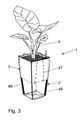
- a plant pot assembly 1 shown in Figs. 1 and 3 comprises a Planter 2 and one insertable into the planter 2 insertion pot 3. In the insert pot 3, a green plant 4 is planted. Both the planter 2 and the insert pot 3 are made of high quality plastic.
- the one-piece pot 2 is thin-walled and open at the top. He is square in cross section and has a square Floor 5, at which the edge side four side walls 6, 7, 8, 9 join. The side walls 6 to 9 extend, starting from the bottom 5, upwards and slightly outwards, d. H. the distance between two opposite ones Sidewalls 6, 8 and 7, 9 gradually expands.
- the Planter 2 has a lower, the bottom 5 enclosing hollow truncated pyramid section 10, to which an upper, hollow truncated pyramid section 11 adjacent.
- the lower truncated pyramid section 10 extends from the bottom 5 to a transition edge 52.
- the planter 2 has a square import opening 12th to which a through the side walls 6 to 9 and the bottom of the fifth limited recording room 13 connects.
- the bottom 5 has a receiving space 13 and the insertion opening 12 facing top 14 on. On the top 14 facing away Side of the bottom 5 there is a bottom 15, which serves as a base acts. The bottom 15 may be flat or after having projecting footprints below.
- the bottom 5 is from a Sicker-opening 16 penetrated, which allows for a connection between the Recording room 13 and the outside environment provides.
- the seepage opening 16 is circular in cross-section and can, for example, a Have internal thread. It is located in the middle of the bottom 5 and is circulated by a ring lug 17 extending from the top 14 of the Floor 5 projects upwards.
- the bottom 5 is by four stiffening struts 18 reinforced, which is connected to the top 14 of the bottom 5 are.
- the stiffening struts 18 each extend from a corner region of the bottom 5 to the ring lug 17. They thus run diagonally. On each stiffening strut 18 is a ring-web 19, in the outer end area is provided and away from a stiffening strut 18 extends upward.
- the ring bridge 19 laterally bounded in the Cross-section circular plug-in opening 20, the upward, d. H. to that Recording room 13 is open.
- the ring-bridge 19 adjoins by the Side walls 6 to 9 formed edges 21 and adjacent to the edges 21 Edge regions 22 on.
- the insertion openings 20 are below locked.
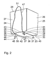
- the one-piece insert pot 3 has a square cross-section and is thin-walled.
- the shape of the insert pot 3 corresponds a truncated pyramid.
- the insert pot 3 has a lower square Floor 23, which is four up and slightly behind outside extending side walls 24, 25, 26, 27 connect. The distance two opposite side walls 24, 26 and 25, 27 expands thus gradually starting from the bottom 23.
- Both the inner contour as well as the outer contour of the insertion pot 3 corresponds to a truncated pyramid.
- the outer contour of the insertion pot 3 substantially corresponds the inner contour of the upper truncated pyramid portion 11 of the planter 2.
- the inclination of the outer sides of the side walls 24 to 27 corresponds essentially the inclination of the inner sides of the side walls 6 to 9 in the Area of the upper truncated pyramid section 11th
- the side walls 24 to 27 and the bottom 23 define a planting space 28, which communicates via an upper opening 29 with the environment stands.
- the insert pot 3 or the planting space 28 is open at the top and serves - as already mentioned - for holding a plant and a Substrate, such as earth.
- the floor 23 has an outwardly facing bottom 31 and one of the bottom 31 facing away from top 32.
- the top 32 is thus the Planting room 28 facing.
- Between the side wall 24 and the floor 23 is an edge 33 before.
- the edge 33 is located opposite an edge 34, the is formed by the side wall 26 and the bottom 23.
- Through the side wall 25 and the bottom 23, an edge 35 is formed while passing through the side wall 27 and the bottom 23 one of the edge 35 opposite Edge 36 is formed.
- the insert pot 3 can also without seepage opening 30 be formed.
- guide lugs extend 37 down, which are arranged in pairs, but spaced from each other. Between each two adjacently arranged guide lugs 37 is located there is a guide gap 38.
- guide lugs 37 are located themselves in an edge region 39 of the Soil 23. These four guidance approaches 37 are on an imaginary line arranged, which runs parallel to the edge 36.
- the other four management approaches 37 are located in an edge region adjacent to the edge 35 40 of the bottom 23.
- the located in the edge region 40 Guide lugs 37 are also arranged on an imaginary line, which runs parallel to the edge 35.
- the edge regions 39, 40 run parallel but spaced from each other.
- the management approaches 37 are also arranged in edge regions 41, 42 of the bottom 23.
- the border area 41 runs adjacent to the edge 34, while the edge region 42 adjacent to the edge 33.
- the mutually parallel edge regions 41, 42 are perpendicular to the edge regions 39, 40.
- the one in the edge region 39 provided pair of guide lugs 37 is located in the edge region 42, while the other is in the edge region 39 Located pair of guide lugs 37 in the edge region 41 is.
- a pair of guide lugs 37 which are in the Edge region 40 are arranged in the edge region 42 and the edge region 41 provided.
- the guide lugs 37 are symmetrical one parallel to the edges 33 and 34 extending center line and to one Arranged the edges 35 and 36 extending center line.
- In every leadership approach 37 is a downwardly open opening 43, which in Cross-section is circular.
- a closure element 44 can be inserted, which is a base 45 and two extending from the base pins 46 has.
- the insertion pins 46 are each circular in cross section.
- the distance of the insertion pins 46 to each other on a closure element 44 corresponds to the distance between two adjacent guide approaches 37.
- the Diameter of a male pin 46 is to the diameter of an opening 43 of a leadership approach 37 adapted.
- the closure elements 44 serve to bridge two adjacent guide approaches 37 and for limiting the guide gap 38 down.
- the plant pot arrangement 1 also comprises a loop-shaped tear-resistant carrying cord 47, whose ends are knotted together. The carrying cord 47 but can also be designed endlessly.
- the plant pot arrangement 1 comprises two circular cross sections trained spacers 48 in the form of spacer bars.
- the diameter of the spacer bars 48 is at the diameter of the Plug-in openings 20 adapted.
- the length of the spacer bars 48 corresponds essentially the height of the lower truncated pyramid section 10th
- the two spacer bars 48 are in two obliquely opposite Insert insertion openings 20 of the planter 2.
- the distance bars 48 lie on the side walls 6 to 9 in the edge areas 22 on.
- the spacer bars 48 are through the insertion openings 20 fixed.
- the carrying cord 47 is so through the guide gaps 38 of the guide lugs 37 lead to a section 49 of the support cord 47 in the edge region 41 and another portion 50 of the support cord 47th in the edge region 42 extends.
- the sections 49, 50 of the carrying line 47 thus run parallel and spaced from each other at the bottom 31st of the bottom 23.
- the guide spaces 38 are through to close the closure elements 44 down.
- the pins 46 in the corresponding openings 43 of the guide lugs 37th introduce.
- the insertion pins 46 can, for example, with the guide lugs 37 are in latching connection or frictionally fixed be.
- the insert pot 3 is by means of the support cord 47 in the shape of the Einsetzopfes 3 adapted pot 2 use.
- the insert pot 3 is to in an insertion direction R via the insertion opening 12 of the planter 3 to insert in its receiving space 13.
- the insertion direction R runs perpendicular to the bottom 5.
- the carrying cord 47 is at loop sections 51 to grab.
- the loop-shaped carrying cord 47 has a Length on which is longer than the sum of the height of two side walls 25, 27 and the side length of the bottom 23 is.
- the loop sections 51 run when wearing the Einsetzopfes 3 over the free upper edge of the same out. It runs on the outside along the side walls 25 and 27th and along the bottom 31 of the bottom 23.
- the loop portions 51 act as handle or handle sections.
- the support cord 47 is located between the side walls 25, 27 of the Einsetzopfes 3 and the side walls 25, 27 opposite side walls 7, 9 of the planter 2.
- the support cord 47 can by a corresponding Choice of the carrying cord diameter or by a corresponding Embodiment of the planter 2 and the insertion pot 3 between be clamped the planter 2 and the insert pot 3. This will prevents the loop portions 51 in the space between Clod 2 and Einsetzopf 3 can slip and thus no longer from are tangible on the outside.
- the loop portions 51 are from the translation pot 3 led.
- the loop portions 51 are in that in the Engage insert pot 3 located substrate. They are not anymore seen. By burying the loop portions 51 but can Also, the support cord 47 are fixed in position to slipping to prevent.
- the Einsetzopf 3 is easily over the loop sections 51 from the Planter 2 against the insertion direction R Couplebbar. Because the sections 49, 50 of the support cord 47 in the edge regions 41, 42 of the soil 5 run, the Einsetzopf 3 can be stably worn. A tilting of the Einsetzopfes 3 is thus when worn by the course of the support cord 47 prevented at the bottom 31. In addition, by the appropriate Course of the support cord 47 easy insertion of Einsetzopfes 3 in the planter 2 and a corresponding lifting made possible. Jamming or jamming will occur both during insertion prevented when lifting.
- the seepage opening 16 liquid-tight by a plug or a Screw from the outside or the bottom 15 to close.
- the plant pot arrangement 1 is thus sealed liquid-tight when used indoors, so that water can not get into the environment. If the Plant pot arrangement 1 is placed outside, should both the seepage opening 16 as well as the seepage opening 30 be unlocked. excess Water can thus from the Einsetzopf 3 and the planter. 2 flow away.
- the Einsetzopf 3 could be set up without pot 2 alone.
- the guide lugs 37 act as supporting feet.
- the seepage opening 30 via a plug or a screw from the bottom 31 from liquid-tight to close. Is the Einsetzopf 3 alone outside set up, the seepage opening 30 should remain unlocked.
- the planter 2 can be weighted, for example, with a weight, which are received in the lower truncated pyramid section 10 can. As a result, the stability of the plant pot assembly 1 before everything against wind be increased substantially.
- the planted Einsetzopf 3 can be comfortable and easy be removed from the planter 2 and another planted insert pot 3 are replaced. This is for example for hotel complexes particularly interesting, as an aggravating moving the Cupping pot 2 is eliminated. Also for nurseries is this fast exchange Of Einsetzmün 3 particularly advantageous.
- the planter 2 can on the outside have decorative ornaments.
Landscapes
- Life Sciences & Earth Sciences (AREA)
- Environmental Sciences (AREA)
- Cultivation Receptacles Or Flower-Pots, Or Pots For Seedlings (AREA)
- Breeding Of Plants And Reproduction By Means Of Culturing (AREA)
- Hydroponics (AREA)
Abstract
Description
- Fig. 1
- eine perspektivische Ansicht einer erfindungsgemäßen Pflanztopf-Anordnung, wobei sich der Einsatztopf außerhalb des Übertopfes befindet;
- Fig. 2
- eine perspektivische Ansicht des in Fig. 1 dargestellten Einsetztopfes von schräg unten; und
- Fig. 3
- eine perspektivische Ansicht der in Fig. 1 dargestellten Pflanztopf-Anordnung, wobei der Einsetztopf in den Übertopf eingesetzt ist.
Claims (10)
- Pflanztopf-Anordnunga) mit einem Übertopf (2),b) mit einem Einsetztopf (3) zur Aufnahme einer Pflanze (4) und zum Einsetzen in den Übertopf (2),i) wobei der Einsetztopf (3) aus dem Übertopf (2) heraushebbar ist, undc) mit mindestens einer mit dem Einsetztopf (3) in Verbindung stehenden Tragschnur (47) zum Herausheben des Einsetztopfes (3) aus dem Übertopf (2) und zum Tragen des Einsetztopfes (3).
- Pflanztopf-Anordnung nach Anspruch 1, dadurch gekennzeichnet, dass der Übertopf (2) einen Übertopf-Boden (5) aufweist und der Einsetztopf (3) einen Einsetztopf-Boden (23) aufweist.
- Pflanztopf-Anordnung nach Anspruch 2, gekennzeichnet durch mindestens ein Abstandselement (48) zur Abstützung des Einsetztopf-Bodens (23) gegenüber dem Übertopf-Boden (5).
- Pflanztopf-Anordnung nach einem der vorherigen Ansprüche, dadurch gekennzeichnet, dass die mindestens eine Tragschnur (47) teilweise an der Unterseite (31) des Einsetztopf-Bodens (23) verläuft.
- Pflanztopf-Anordnung nach Anspruch 4, dadurch gekennzeichnet, dass die mindestens eine Tragschnur (47) an der Unterseite (31) des Einsetztopf-Bodens (23) geführt verläuft.
- Pflanztopf-Anordnung nach einem der vorherigen Ansprüche, dadurch gekennzeichnet, dass von der Unterseite (31) des Einsetztopf-Bodens (23) mindestens ein Paar voneinander beabstandeter Führungsansätze (37) zur Führung der Tragschnur (47) vorspringt.
- Pflanztopf-Anordnung nach Anspruch 6, dadurch gekennzeichnet, dass in jeweils zwei paarweise angeordnete Führungsansätze (37) ein diese miteinander verbindendes Verschlusselement (44) zur Führung der Tragschnur (47) einsteckbar ist.
- Pflanztopf-Anordnung nach einem der vorherigen Ansprüche, dadurch gekennzeichnet, dass eine schlaufenförmige Tragschnur (47) vorgesehen ist.
- Pflanztopf-Anordnung nach Anspruch 8, dadurch gekennzeichnet, dass die Tragschnur (47) zwei Abschnitte (49, 50) aufweist, die an der Unterseite (31) des Einsetztopf-Bodens (23) in zwei einander gegenüberliegenden Randbereichen (41, 42) des Einsetztopf-Bodens (23) verlaufen.
- Pflanztopf-Anordnung nach Anspruch 8, dadurch gekennzeichnet, dass die Tragschnur (47) zwei aus dem Übersetztopf (2) herausgeführte Schlaufenabschnitte (51) aufweist.
Applications Claiming Priority (2)
| Application Number | Priority Date | Filing Date | Title |
|---|---|---|---|
| DE102004022223 | 2004-05-04 | ||
| DE102004022223A DE102004022223A1 (de) | 2004-05-04 | 2004-05-04 | Pflanzkübel mit heraushebbarem Einsatz |
Publications (2)
| Publication Number | Publication Date |
|---|---|
| EP1593301A1 true EP1593301A1 (de) | 2005-11-09 |
| EP1593301B1 EP1593301B1 (de) | 2007-12-19 |
Family
ID=34935264
Family Applications (1)
| Application Number | Title | Priority Date | Filing Date |
|---|---|---|---|
| EP05008341A Expired - Lifetime EP1593301B1 (de) | 2004-05-04 | 2005-04-16 | Pflanztopf-Anordnung |
Country Status (3)
| Country | Link |
|---|---|
| EP (1) | EP1593301B1 (de) |
| AT (1) | ATE381257T1 (de) |
| DE (2) | DE102004022223A1 (de) |
Cited By (3)
| Publication number | Priority date | Publication date | Assignee | Title |
|---|---|---|---|---|
| DE202005018519U1 (de) * | 2005-11-26 | 2007-04-05 | Geobra Brandstätter GmbH & Co. KG | Pflanztopf-Anordnung |
| CN101711497B (zh) * | 2008-09-29 | 2014-07-16 | 杰伯拉布兰德施泰特有限及两合公司 | 插入容器 |
| RU2851156C1 (ru) * | 2025-03-07 | 2025-11-19 | Мария Михайловна Блинова | Модульный горшок для выращивания растений |
Families Citing this family (2)
| Publication number | Priority date | Publication date | Assignee | Title |
|---|---|---|---|---|
| DE102006036479B4 (de) * | 2006-08-04 | 2008-09-04 | Geobra Brandstätter GmbH & Co. KG | Pflanztopf-Anordnung |
| DE202012102743U1 (de) | 2012-07-23 | 2013-10-24 | The Tam Ngo | Pflanzbehältnis-Anordnung |
Citations (3)
| Publication number | Priority date | Publication date | Assignee | Title |
|---|---|---|---|---|
| EP0249027A1 (de) * | 1986-05-09 | 1987-12-16 | Luis Cabre Roige | Pflanzkasten |
| DE4004136C1 (en) | 1990-02-10 | 1991-06-13 | Josef 8172 Lenggries De Hoeller | Flower pot assembly with outer and inner pots - has several protrusions in peripheral top edge of inner pot, engaging outer pot recesses |
| GB2384159A (en) * | 2002-01-14 | 2003-07-23 | John Kennedy Fletcher | Potted plant remover |
Family Cites Families (3)
| Publication number | Priority date | Publication date | Assignee | Title |
|---|---|---|---|---|
| DE7148022U (de) * | 1972-08-10 | Nicke H | Behälter für die Bodenkultur und Lagerung von Blumenzwiebeln und -knollen | |
| DE7107036U (de) * | 1971-08-26 | Rudolph Heinrich | Expositionsgefäß | |
| DE10327175A1 (de) * | 2003-06-06 | 2004-12-23 | Christian Albrecht | Umtopfhilfselement |
-
2004
- 2004-05-04 DE DE102004022223A patent/DE102004022223A1/de not_active Withdrawn
-
2005
- 2005-04-16 EP EP05008341A patent/EP1593301B1/de not_active Expired - Lifetime
- 2005-04-16 DE DE502005002262T patent/DE502005002262D1/de not_active Expired - Fee Related
- 2005-04-16 AT AT05008341T patent/ATE381257T1/de not_active IP Right Cessation
Patent Citations (3)
| Publication number | Priority date | Publication date | Assignee | Title |
|---|---|---|---|---|
| EP0249027A1 (de) * | 1986-05-09 | 1987-12-16 | Luis Cabre Roige | Pflanzkasten |
| DE4004136C1 (en) | 1990-02-10 | 1991-06-13 | Josef 8172 Lenggries De Hoeller | Flower pot assembly with outer and inner pots - has several protrusions in peripheral top edge of inner pot, engaging outer pot recesses |
| GB2384159A (en) * | 2002-01-14 | 2003-07-23 | John Kennedy Fletcher | Potted plant remover |
Cited By (5)
| Publication number | Priority date | Publication date | Assignee | Title |
|---|---|---|---|---|
| DE202005018519U1 (de) * | 2005-11-26 | 2007-04-05 | Geobra Brandstätter GmbH & Co. KG | Pflanztopf-Anordnung |
| US7805886B2 (en) | 2005-11-26 | 2010-10-05 | Geobra Brandstatter Gmbh & Co. Kg | Plant pot arrangement |
| CN1969609B (zh) * | 2005-11-26 | 2010-11-10 | 杰伯拉布兰德施泰特有限及两合公司 | 花盆装置 |
| CN101711497B (zh) * | 2008-09-29 | 2014-07-16 | 杰伯拉布兰德施泰特有限及两合公司 | 插入容器 |
| RU2851156C1 (ru) * | 2025-03-07 | 2025-11-19 | Мария Михайловна Блинова | Модульный горшок для выращивания растений |
Also Published As
| Publication number | Publication date |
|---|---|
| DE102004022223A1 (de) | 2005-12-01 |
| ATE381257T1 (de) | 2008-01-15 |
| EP1593301B1 (de) | 2007-12-19 |
| DE502005002262D1 (de) | 2008-01-31 |
Similar Documents
| Publication | Publication Date | Title |
|---|---|---|
| DE69313992T2 (de) | Struktur für Kinderspiele | |
| EP3576518B1 (de) | Tray zum kultivieren von pflanzen und system umfassend tray und pflanztopf | |
| EP1686037B1 (de) | Bewässerungs- und Transportvorrichtung für Pflanzen | |
| DE3443634A1 (de) | Neigungsverstellbarer stuetzbock | |
| DE202018006143U1 (de) | Fallschutzbodenelement vorzugsweise zum Abdecken von Spielplätzen und daraus zusammengesetzter Böden | |
| DE3301159A1 (de) | In drei ebenen wahlweise uebereinander und ineinander stapelbare container | |
| WO2017008893A1 (de) | Palette für pflanztopfe | |
| EP1426521A2 (de) | Vorbau für Wände | |
| EP1593301B1 (de) | Pflanztopf-Anordnung | |
| DE202009008128U1 (de) | Vase | |
| DE202023102618U1 (de) | Bein eines Metallregals | |
| DE102017102773B3 (de) | Bepflanzbare Vorrichtung sowie Bausatz zur Herstellung einer bepflanzbaren Vorrichtung | |
| DE102008014903A1 (de) | Halbmodul und Halbelement der verlorenen Schalung, und Verfahren zum Bau von Schwimmbädern | |
| EP0988783A2 (de) | Kulturplatte zum Bewurzeln von Jungpflanzen | |
| DE7835331U1 (de) | Haltevorrichtung, insbesondere fuer pflanzenkulturen o.dgl. | |
| DE2331413C3 (de) | Gitterähnliche Unterdecke | |
| DE60219974T2 (de) | Paneelsystem | |
| DE1482977A1 (de) | Anzuchttopf aus Kunststoff | |
| DE102012107524B4 (de) | Einheit aus zwei Einrichtungen zur Präsentation und/oder Aufnahme von Gegenständen | |
| CH709249A2 (de) | Pflanzbeet-Vorrichtung. | |
| DE202019100061U1 (de) | Stapelbarer Pflanztopf | |
| DE20021030U1 (de) | Flächen-Einfassungs-System für gärtnerische Anlagen | |
| DE3734074C2 (de) | ||
| DE102008049362A1 (de) | Modulares Bewässerungs-System | |
| EP3117702B1 (de) | Pflanztunnelelement zum abdecken von pflanzen |
Legal Events
| Date | Code | Title | Description |
|---|---|---|---|
| PUAI | Public reference made under article 153(3) epc to a published international application that has entered the european phase |
Free format text: ORIGINAL CODE: 0009012 |
|
| AK | Designated contracting states |
Kind code of ref document: A1 Designated state(s): AT BE BG CH CY CZ DE DK EE ES FI FR GB GR HU IE IS IT LI LT LU MC NL PL PT RO SE SI SK TR |
|
| AX | Request for extension of the european patent |
Extension state: AL BA HR LV MK YU |
|
| 17P | Request for examination filed |
Effective date: 20060317 |
|
| AKX | Designation fees paid |
Designated state(s): AT BE BG CH CY CZ DE DK EE ES FI FR GB GR HU IE IS IT LI LT LU MC NL PL PT RO SE SI SK TR |
|
| GRAP | Despatch of communication of intention to grant a patent |
Free format text: ORIGINAL CODE: EPIDOSNIGR1 |
|
| GRAS | Grant fee paid |
Free format text: ORIGINAL CODE: EPIDOSNIGR3 |
|
| GRAA | (expected) grant |
Free format text: ORIGINAL CODE: 0009210 |
|
| AK | Designated contracting states |
Kind code of ref document: B1 Designated state(s): AT BE BG CH CY CZ DE DK EE ES FI FR GB GR HU IE IS IT LI LT LU MC NL PL PT RO SE SI SK TR |
|
| REG | Reference to a national code |
Ref country code: GB Ref legal event code: FG4D Free format text: NOT ENGLISH |
|
| REG | Reference to a national code |
Ref country code: IE Ref legal event code: FG4D Free format text: LANGUAGE OF EP DOCUMENT: GERMAN |
|
| REG | Reference to a national code |
Ref country code: CH Ref legal event code: EP |
|
| REF | Corresponds to: |
Ref document number: 502005002262 Country of ref document: DE Date of ref document: 20080131 Kind code of ref document: P |
|
| PG25 | Lapsed in a contracting state [announced via postgrant information from national office to epo] |
Ref country code: SE Free format text: LAPSE BECAUSE OF FAILURE TO SUBMIT A TRANSLATION OF THE DESCRIPTION OR TO PAY THE FEE WITHIN THE PRESCRIBED TIME-LIMIT Effective date: 20080319 |
|
| PG25 | Lapsed in a contracting state [announced via postgrant information from national office to epo] |
Ref country code: FI Free format text: LAPSE BECAUSE OF FAILURE TO SUBMIT A TRANSLATION OF THE DESCRIPTION OR TO PAY THE FEE WITHIN THE PRESCRIBED TIME-LIMIT Effective date: 20071219 Ref country code: LT Free format text: LAPSE BECAUSE OF FAILURE TO SUBMIT A TRANSLATION OF THE DESCRIPTION OR TO PAY THE FEE WITHIN THE PRESCRIBED TIME-LIMIT Effective date: 20071219 Ref country code: SI Free format text: LAPSE BECAUSE OF FAILURE TO SUBMIT A TRANSLATION OF THE DESCRIPTION OR TO PAY THE FEE WITHIN THE PRESCRIBED TIME-LIMIT Effective date: 20071219 Ref country code: PL Free format text: LAPSE BECAUSE OF FAILURE TO SUBMIT A TRANSLATION OF THE DESCRIPTION OR TO PAY THE FEE WITHIN THE PRESCRIBED TIME-LIMIT Effective date: 20071219 Ref country code: NL Free format text: LAPSE BECAUSE OF FAILURE TO SUBMIT A TRANSLATION OF THE DESCRIPTION OR TO PAY THE FEE WITHIN THE PRESCRIBED TIME-LIMIT Effective date: 20071219 |
|
| NLV1 | Nl: lapsed or annulled due to failure to fulfill the requirements of art. 29p and 29m of the patents act | ||
| GBV | Gb: ep patent (uk) treated as always having been void in accordance with gb section 77(7)/1977 [no translation filed] | ||
| ET | Fr: translation filed | ||
| PG25 | Lapsed in a contracting state [announced via postgrant information from national office to epo] |
Ref country code: IS Free format text: LAPSE BECAUSE OF FAILURE TO SUBMIT A TRANSLATION OF THE DESCRIPTION OR TO PAY THE FEE WITHIN THE PRESCRIBED TIME-LIMIT Effective date: 20080419 Ref country code: ES Free format text: LAPSE BECAUSE OF FAILURE TO SUBMIT A TRANSLATION OF THE DESCRIPTION OR TO PAY THE FEE WITHIN THE PRESCRIBED TIME-LIMIT Effective date: 20080330 Ref country code: CZ Free format text: LAPSE BECAUSE OF FAILURE TO SUBMIT A TRANSLATION OF THE DESCRIPTION OR TO PAY THE FEE WITHIN THE PRESCRIBED TIME-LIMIT Effective date: 20071219 |
|
| PG25 | Lapsed in a contracting state [announced via postgrant information from national office to epo] |
Ref country code: SK Free format text: LAPSE BECAUSE OF FAILURE TO SUBMIT A TRANSLATION OF THE DESCRIPTION OR TO PAY THE FEE WITHIN THE PRESCRIBED TIME-LIMIT Effective date: 20071219 Ref country code: RO Free format text: LAPSE BECAUSE OF FAILURE TO SUBMIT A TRANSLATION OF THE DESCRIPTION OR TO PAY THE FEE WITHIN THE PRESCRIBED TIME-LIMIT Effective date: 20071219 |
|
| PG25 | Lapsed in a contracting state [announced via postgrant information from national office to epo] |
Ref country code: PT Free format text: LAPSE BECAUSE OF FAILURE TO SUBMIT A TRANSLATION OF THE DESCRIPTION OR TO PAY THE FEE WITHIN THE PRESCRIBED TIME-LIMIT Effective date: 20080519 |
|
| REG | Reference to a national code |
Ref country code: IE Ref legal event code: FD4D |
|
| PLBE | No opposition filed within time limit |
Free format text: ORIGINAL CODE: 0009261 |
|
| STAA | Information on the status of an ep patent application or granted ep patent |
Free format text: STATUS: NO OPPOSITION FILED WITHIN TIME LIMIT |
|
| BERE | Be: lapsed |
Owner name: GEOBRA BRANDSTATTER G.M.B.H. & CO. KG Effective date: 20080430 |
|
| PG25 | Lapsed in a contracting state [announced via postgrant information from national office to epo] |
Ref country code: IE Free format text: LAPSE BECAUSE OF FAILURE TO SUBMIT A TRANSLATION OF THE DESCRIPTION OR TO PAY THE FEE WITHIN THE PRESCRIBED TIME-LIMIT Effective date: 20071219 Ref country code: DK Free format text: LAPSE BECAUSE OF FAILURE TO SUBMIT A TRANSLATION OF THE DESCRIPTION OR TO PAY THE FEE WITHIN THE PRESCRIBED TIME-LIMIT Effective date: 20071219 |
|
| 26N | No opposition filed |
Effective date: 20080922 |
|
| PG25 | Lapsed in a contracting state [announced via postgrant information from national office to epo] |
Ref country code: MC Free format text: LAPSE BECAUSE OF NON-PAYMENT OF DUE FEES Effective date: 20080430 Ref country code: GB Free format text: LAPSE BECAUSE OF FAILURE TO SUBMIT A TRANSLATION OF THE DESCRIPTION OR TO PAY THE FEE WITHIN THE PRESCRIBED TIME-LIMIT Effective date: 20071219 |
|
| PG25 | Lapsed in a contracting state [announced via postgrant information from national office to epo] |
Ref country code: EE Free format text: LAPSE BECAUSE OF FAILURE TO SUBMIT A TRANSLATION OF THE DESCRIPTION OR TO PAY THE FEE WITHIN THE PRESCRIBED TIME-LIMIT Effective date: 20071219 Ref country code: GR Free format text: LAPSE BECAUSE OF FAILURE TO SUBMIT A TRANSLATION OF THE DESCRIPTION OR TO PAY THE FEE WITHIN THE PRESCRIBED TIME-LIMIT Effective date: 20080320 |
|
| PG25 | Lapsed in a contracting state [announced via postgrant information from national office to epo] |
Ref country code: BE Free format text: LAPSE BECAUSE OF NON-PAYMENT OF DUE FEES Effective date: 20080430 |
|
| PG25 | Lapsed in a contracting state [announced via postgrant information from national office to epo] |
Ref country code: BG Free format text: LAPSE BECAUSE OF FAILURE TO SUBMIT A TRANSLATION OF THE DESCRIPTION OR TO PAY THE FEE WITHIN THE PRESCRIBED TIME-LIMIT Effective date: 20080319 |
|
| PG25 | Lapsed in a contracting state [announced via postgrant information from national office to epo] |
Ref country code: CY Free format text: LAPSE BECAUSE OF FAILURE TO SUBMIT A TRANSLATION OF THE DESCRIPTION OR TO PAY THE FEE WITHIN THE PRESCRIBED TIME-LIMIT Effective date: 20071219 |
|
| PG25 | Lapsed in a contracting state [announced via postgrant information from national office to epo] |
Ref country code: AT Free format text: LAPSE BECAUSE OF NON-PAYMENT OF DUE FEES Effective date: 20080416 |
|
| PGFP | Annual fee paid to national office [announced via postgrant information from national office to epo] |
Ref country code: FR Payment date: 20090420 Year of fee payment: 5 |
|
| PGFP | Annual fee paid to national office [announced via postgrant information from national office to epo] |
Ref country code: DE Payment date: 20090617 Year of fee payment: 5 |
|
| REG | Reference to a national code |
Ref country code: CH Ref legal event code: PL |
|
| PG25 | Lapsed in a contracting state [announced via postgrant information from national office to epo] |
Ref country code: CH Free format text: LAPSE BECAUSE OF NON-PAYMENT OF DUE FEES Effective date: 20090430 Ref country code: LI Free format text: LAPSE BECAUSE OF NON-PAYMENT OF DUE FEES Effective date: 20090430 |
|
| PG25 | Lapsed in a contracting state [announced via postgrant information from national office to epo] |
Ref country code: HU Free format text: LAPSE BECAUSE OF FAILURE TO SUBMIT A TRANSLATION OF THE DESCRIPTION OR TO PAY THE FEE WITHIN THE PRESCRIBED TIME-LIMIT Effective date: 20080620 Ref country code: LU Free format text: LAPSE BECAUSE OF NON-PAYMENT OF DUE FEES Effective date: 20080416 |
|
| PG25 | Lapsed in a contracting state [announced via postgrant information from national office to epo] |
Ref country code: TR Free format text: LAPSE BECAUSE OF FAILURE TO SUBMIT A TRANSLATION OF THE DESCRIPTION OR TO PAY THE FEE WITHIN THE PRESCRIBED TIME-LIMIT Effective date: 20071219 |
|
| REG | Reference to a national code |
Ref country code: FR Ref legal event code: ST Effective date: 20101230 |
|
| PG25 | Lapsed in a contracting state [announced via postgrant information from national office to epo] |
Ref country code: FR Free format text: LAPSE BECAUSE OF NON-PAYMENT OF DUE FEES Effective date: 20100430 |
|
| PG25 | Lapsed in a contracting state [announced via postgrant information from national office to epo] |
Ref country code: IT Free format text: LAPSE BECAUSE OF NON-PAYMENT OF DUE FEES Effective date: 20080430 Ref country code: DE Free format text: LAPSE BECAUSE OF NON-PAYMENT OF DUE FEES Effective date: 20101103 |