EP1593542B1 - Sitz für ein gepanzertes Fahrzeug - Google Patents
Sitz für ein gepanzertes Fahrzeug Download PDFInfo
- Publication number
- EP1593542B1 EP1593542B1 EP05450078A EP05450078A EP1593542B1 EP 1593542 B1 EP1593542 B1 EP 1593542B1 EP 05450078 A EP05450078 A EP 05450078A EP 05450078 A EP05450078 A EP 05450078A EP 1593542 B1 EP1593542 B1 EP 1593542B1
- Authority
- EP
- European Patent Office
- Prior art keywords
- seat
- seat according
- previous
- support
- vehicle
- Prior art date
- Legal status (The legal status is an assumption and is not a legal conclusion. Google has not performed a legal analysis and makes no representation as to the accuracy of the status listed.)
- Expired - Lifetime
Links
Images


Classifications
-
- F—MECHANICAL ENGINEERING; LIGHTING; HEATING; WEAPONS; BLASTING
- F41—WEAPONS
- F41H—ARMOUR; ARMOURED TURRETS; ARMOURED OR ARMED VEHICLES; MEANS OF ATTACK OR DEFENCE, e.g. CAMOUFLAGE, IN GENERAL
- F41H7/00—Armoured or armed vehicles
- F41H7/02—Land vehicles with enclosing armour, e.g. tanks
- F41H7/04—Armour construction
- F41H7/046—Shock resilient mounted seats for armoured or fighting vehicles
-
- B—PERFORMING OPERATIONS; TRANSPORTING
- B60—VEHICLES IN GENERAL
- B60N—SEATS SPECIALLY ADAPTED FOR VEHICLES; VEHICLE PASSENGER ACCOMMODATION NOT OTHERWISE PROVIDED FOR
- B60N2/00—Seats specially adapted for vehicles; Arrangement or mounting of seats in vehicles
- B60N2/005—Arrangement or mounting of seats in vehicles, e.g. dismountable auxiliary seats
- B60N2/01—Arrangement of seats relative to one another
-
- B—PERFORMING OPERATIONS; TRANSPORTING
- B60—VEHICLES IN GENERAL
- B60N—SEATS SPECIALLY ADAPTED FOR VEHICLES; VEHICLE PASSENGER ACCOMMODATION NOT OTHERWISE PROVIDED FOR
- B60N2/00—Seats specially adapted for vehicles; Arrangement or mounting of seats in vehicles
- B60N2/005—Arrangement or mounting of seats in vehicles, e.g. dismountable auxiliary seats
- B60N2/015—Attaching seats directly to vehicle chassis
-
- B—PERFORMING OPERATIONS; TRANSPORTING
- B60—VEHICLES IN GENERAL
- B60N—SEATS SPECIALLY ADAPTED FOR VEHICLES; VEHICLE PASSENGER ACCOMMODATION NOT OTHERWISE PROVIDED FOR
- B60N2/00—Seats specially adapted for vehicles; Arrangement or mounting of seats in vehicles
- B60N2/24—Seats specially adapted for vehicles; Arrangement or mounting of seats in vehicles for particular purposes or particular vehicles
-
- B—PERFORMING OPERATIONS; TRANSPORTING
- B60—VEHICLES IN GENERAL
- B60N—SEATS SPECIALLY ADAPTED FOR VEHICLES; VEHICLE PASSENGER ACCOMMODATION NOT OTHERWISE PROVIDED FOR
- B60N2/00—Seats specially adapted for vehicles; Arrangement or mounting of seats in vehicles
- B60N2/24—Seats specially adapted for vehicles; Arrangement or mounting of seats in vehicles for particular purposes or particular vehicles
- B60N2/30—Non-dismountable or dismountable seats storable in a non-use position, e.g. foldable spare seats
- B60N2/3038—Cushion movements
- B60N2/304—Cushion movements by rotation only
- B60N2/3045—Cushion movements by rotation only about transversal axis
- B60N2/3047—Cushion movements by rotation only about transversal axis the cushion being hinged at the back-rest
-
- B—PERFORMING OPERATIONS; TRANSPORTING
- B60—VEHICLES IN GENERAL
- B60N—SEATS SPECIALLY ADAPTED FOR VEHICLES; VEHICLE PASSENGER ACCOMMODATION NOT OTHERWISE PROVIDED FOR
- B60N2/00—Seats specially adapted for vehicles; Arrangement or mounting of seats in vehicles
- B60N2/24—Seats specially adapted for vehicles; Arrangement or mounting of seats in vehicles for particular purposes or particular vehicles
- B60N2/42—Seats specially adapted for vehicles; Arrangement or mounting of seats in vehicles for particular purposes or particular vehicles the seat constructed to protect the occupant from the effect of abnormal g-forces, e.g. crash or safety seats
- B60N2/4207—Seats specially adapted for vehicles; Arrangement or mounting of seats in vehicles for particular purposes or particular vehicles the seat constructed to protect the occupant from the effect of abnormal g-forces, e.g. crash or safety seats characterised by the direction of the g-forces
- B60N2/4242—Seats specially adapted for vehicles; Arrangement or mounting of seats in vehicles for particular purposes or particular vehicles the seat constructed to protect the occupant from the effect of abnormal g-forces, e.g. crash or safety seats characterised by the direction of the g-forces vertical
-
- B—PERFORMING OPERATIONS; TRANSPORTING
- B60—VEHICLES IN GENERAL
- B60N—SEATS SPECIALLY ADAPTED FOR VEHICLES; VEHICLE PASSENGER ACCOMMODATION NOT OTHERWISE PROVIDED FOR
- B60N2/00—Seats specially adapted for vehicles; Arrangement or mounting of seats in vehicles
- B60N2/24—Seats specially adapted for vehicles; Arrangement or mounting of seats in vehicles for particular purposes or particular vehicles
- B60N2/42—Seats specially adapted for vehicles; Arrangement or mounting of seats in vehicles for particular purposes or particular vehicles the seat constructed to protect the occupant from the effect of abnormal g-forces, e.g. crash or safety seats
- B60N2/427—Seats or parts thereof displaced during a crash
- B60N2/42709—Seats or parts thereof displaced during a crash involving residual deformation or fracture of the structure
-
- B—PERFORMING OPERATIONS; TRANSPORTING
- B60—VEHICLES IN GENERAL
- B60N—SEATS SPECIALLY ADAPTED FOR VEHICLES; VEHICLE PASSENGER ACCOMMODATION NOT OTHERWISE PROVIDED FOR
- B60N3/00—Arrangements or adaptations of other passenger fittings, not otherwise provided for
- B60N3/06—Arrangements or adaptations of other passenger fittings, not otherwise provided for of footrests
- B60N3/063—Arrangements or adaptations of other passenger fittings, not otherwise provided for of footrests with adjustment systems
-
- B—PERFORMING OPERATIONS; TRANSPORTING
- B60—VEHICLES IN GENERAL
- B60R—VEHICLES, VEHICLE FITTINGS, OR VEHICLE PARTS, NOT OTHERWISE PROVIDED FOR
- B60R22/00—Safety belts or body harnesses in vehicles
- B60R22/12—Construction of belts or harnesses
- B60R22/14—Construction of belts or harnesses incorporating enlarged restraint areas, e.g. vests, nets, crash pads, optionally for children
-
- B—PERFORMING OPERATIONS; TRANSPORTING
- B60—VEHICLES IN GENERAL
- B60R—VEHICLES, VEHICLE FITTINGS, OR VEHICLE PARTS, NOT OTHERWISE PROVIDED FOR
- B60R21/00—Arrangements or fittings on vehicles for protecting or preventing injuries to occupants or pedestrians in case of accidents or other traffic risks
- B60R2021/003—Arrangements or fittings on vehicles for protecting or preventing injuries to occupants or pedestrians in case of accidents or other traffic risks characterised by occupant or pedestian
- B60R2021/0039—Body parts of the occupant or pedestrian affected by the accident
- B60R2021/0048—Head
-
- B—PERFORMING OPERATIONS; TRANSPORTING
- B60—VEHICLES IN GENERAL
- B60R—VEHICLES, VEHICLE FITTINGS, OR VEHICLE PARTS, NOT OTHERWISE PROVIDED FOR
- B60R22/00—Safety belts or body harnesses in vehicles
- B60R22/02—Semi-passive restraint systems, e.g. systems applied or removed automatically but not both ; Manual restraint systems
- B60R2022/027—Four-point seat belt systems, e.g. with the two upper points connected together
-
- B—PERFORMING OPERATIONS; TRANSPORTING
- B60—VEHICLES IN GENERAL
- B60R—VEHICLES, VEHICLE FITTINGS, OR VEHICLE PARTS, NOT OTHERWISE PROVIDED FOR
- B60R22/00—Safety belts or body harnesses in vehicles
- B60R22/18—Anchoring devices
- B60R22/26—Anchoring devices secured to the seat
Definitions
- the invention relates to a seat for an armored vehicle, which is attached to the protection against landmines on an upper suspension and having a seat cover and a restraint system.
- An effective protection for the crew depends essentially on the design of the seats and their attachment in the armored vehicle.
- An attachment of the seats on the ground or on the side wall is unsuitable for a mine-protected design, since at a mine detonation of the vehicle floor is accelerated so much that the forces transmitted to the occupants is a multiple of the physiologically acceptable acceleration.
- To protect the occupants it is imperative that the seat attachment takes place on the vehicle roof, where caused by the mine detonation vertical acceleration is much lower than at the vehicle floor, since the vehicle floor is additionally highly dynamically and plastically deformed by the direct force of the detonation pressure.
- EP 1382932 A1 is described a safety seat system, which takes into account this required decoupling of the seats from the vehicle floor and from the side wall by the seat is suspended from the vehicle roof and braced against the floor.
- seats have the significant disadvantage that they retain their protection only in undeformed soil structure. Due to the significant dynamic buckling of the soil structure of the seat can lose its predetermined by the strained straps fixation, and thus its rigid shape, since the straps fixed to the ground are loosened.
- a seat according to the preamble of claim 1 is described, which is attached to a linkage, which is attached to the side wall, in particular a helicopter, but can also be attached to the ceiling or the floor.
- the linkage cooperates with a damping system comprising a bending device.
- the aim of the present invention is to provide a seat of the type mentioned, in which the force is minimized to the vehicle crew in the event of mine detonation, so that the occupants are protected in the best possible way from injury.
- an inventively designed seat lacks any tension to the ground, so that a deformation of the floor does not affect the seat and in particular its occupants. Nevertheless, according to the elastic suspension straps secure attachment of the seat is guaranteed.
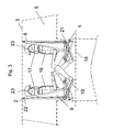
- the seat is guided by a suspension linkage 1, which is fastened to the vehicle roof 3 by means of an articulated suspension 2.
- a power transmission can thus be carried out in bilateral Gestfiteraum.
- each suspension linkage 1 For lateral guidance of each suspension linkage 1 is provided with a bearing 4, which is firmly connected to the side wall 21 of the vehicle 5.
- the design of this bearing 4 is designed so that in no case a deadlock in the vehicle vertical axis can occur and thus it is ensured that no vertical forces in the suspension linkage 1 can be initiated. Only lateral forces can be transmitted, but no forces may be directed into the seat from the ground side towards the suspension linkage 1, as typically occurs in mine detonation under the vehicle.
- the bearing 4 In order to also elastically initiate forces acting laterally on the seat, the bearing 4 is placed clearly outside the center of gravity of the loaded seat to spring through the elastic deformation of the suspension linkage 1, the forces introduced via the bearing 4 of the side wall 21 accordingly.
- Fig. 4 shows a preferred embodiment of this side guide 4 by means of rollers, which allows a precise and almost play-free guidance; but the guide can also be achieved with any other guide means, such as a belt, or with corresponding straps, for example, diagonally braced to the side wall.
- the specially shaped seat upholstery ensures better seating comfort and extra safety.
- the seat upholstery consists essentially of two elastic straps 6 and the seat cover, which consists of the backrest 7, the seat surface 8 and the two side guide cheeks 9, which are preferably all connected to each other, preferably sewn.
- This seat cover is made of an elastic material, preferably textile, in addition to the individual person protection, depending on the requirements, a single or multi-layer splinter protection material can be introduced.
- the backrest 7 is designed so that it also serves as a headrest due to their height.
- the elastic belt 6 is, as exemplified in Fig. 5 is shown attached to the upper end 22 removably attached to the vehicle roof 3, and is sewn to the seat cover, especially with the side guide cheek 9.
- the seat upholstery is fastened with its seating surface 8 on the ergonomically shaped seat frame 10.
- the occupants 16 are pressed into the ergonomically shaped seat fabric, which reduces due to the elastic material, the acceleration force that comes to the occupants 16 to work. In the opposite direction, the occupants 16 are held by the seat belt. The entire seat is supported via the linkage 1 from the vehicle roof 3 and is held in position via the side guides 4.
- the seat frame 10 is limited by the elastic belt 6, which is fixed to the vehicle roof 3 on the suspension 2 in its lowest position, and is automatically folded when not using the seat together with the seat cover by means of a spring (not shown) upwards.
- the vertical upward acceleration of the occupants 16 is substantially supported by the seat surface 8 and held by the elastic belt 6.
- this belt 6 may additionally be provided with one or more S-shaped loops 11 (FIG. Fig. 5 ), preferably sewn or glued, in order to install an energy-consuming predetermined breaking point in the case of the impending overrun of these limits while fully maintaining the protective and support function for the occupants 16.
- S-shaped loops 11 FIG. Fig. 5
- the acceleration force is transmitted to the fabric of the side guide cheeks 9 when tearing the S-loop 11, which subsequently tearing energy-consuming which further enhances this desired energy absorbing effect.
- the underside of the seat 8 can be additionally equipped with a stowage pocket.
- the seat In order to fix the occupants 16 in the seat, the seat is equipped with a belt restraint system 12. The fixation of the occupant 16 in the seat is carried out both with a Hosenany- 13 and with a waist belt 14. The attachment of Gurtschhaltesystems takes place on the front seat frame 10 and is deflected on a connecting rod 15 between the two suspension linkage 1. By this combination, one achieves the desired retention property of the occupants 16, because the seat belts 12, 13, 14 fix the occupant 16 in the seat, and by the linkage 1 also an upward force can be transmitted.
- a headrest 17 which is easy to remove is made of an elastic material, e.g. a molded plastic foam, is integrated into the harness belt 13 in such a way that it is placed as needed around the neck of the occupant 16 like a protective collar, which protects the head from lateral kinking. If the protective collar is not used, it can be easily removed and stored separately.
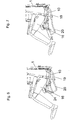
- the seat is additionally equipped with a folding footrest 19, which is connected to the seat frame 10 and the linkage 1.
- the opposite seat occupant 16 can support their feet on the footrest 19, and thus have no contact with the legs to the vehicle floor 18.
- the seat assembly in the vehicle 5 too large a distance between the individual seats to use the footrests 19 results, they can be provided with a telescopic extension 20, which is adapted to the distance of the seats.
- 6 and 7 show two possible versions with different extension length of the footrests. When not using the footrest 19, this can be easily folded up in a space-saving manner and fixed, for example, with a Velcro strip 24 on the seat frame 10.
Landscapes
- Engineering & Computer Science (AREA)
- Mechanical Engineering (AREA)
- Transportation (AREA)
- Aviation & Aerospace Engineering (AREA)
- Textile Engineering (AREA)
- General Engineering & Computer Science (AREA)
- Seats For Vehicles (AREA)
- Aiming, Guidance, Guns With A Light Source, Armor, Camouflage, And Targets (AREA)
- Fluid-Damping Devices (AREA)
- Plural Heterocyclic Compounds (AREA)
Description
- Die Erfindung bezieht sich auf einen Sitz für ein gepanzertes Fahrzeug, der zum Schutz gegen Landminen an einer oberen Aufhängung befestigt ist und einen Sitzbezug sowie ein Rückhaltesystem aufweist.
- Landminen sind aufgrund ihrer extrem hohen Zerstörungskraft verbunden mit einem häufigen Vorkommen in Krisen- und Kriegsgebieten eine große Gefahr für Fahrzeuge und deren Besatzung. Da insbesondere bei friedenssichernden Einsätzen die Wahrscheinlichkeit auf Minen aufzufahren hoch ist, werden auch bei leicht gepanzerten Fahrzeugen höchste Anforderungen an den Schutz gegen Landminen gestellt.
- Ein effektiver Schutz für die Mannschaft hängt wesentlich von der Gestaltung der Sitze und deren Befestigung im gepanzerten Fahrzeug ab. Eine Befestigung der Sitze am Boden bzw. an der Seitenwand ist für eine minengeschützte Ausführung untauglich, da bei einer Minendetonation der Fahrzeugboden so sehr beschleunigt wird, daß die auf die Insassen übertragenen Kräfte ein Vielfaches der physiologisch zulässigen Beschleunigung beträgt. Zum Schutz der Insassen ist es unbedingt erforderlich, daß die Sitzbefestigung am Fahrzeugdach erfolgt, wo die durch die Minendetonation verursachte Vertikalbeschleunigung wesentlich geringer ist als am Fahrzeugboden, da der Fahrzeugboden durch die unmittelbare Krafteinwirkung des Detonationsdruckes zusätzlich hochdynamisch elastisch und plastisch verformt wird.
- In
EP 1382932 A1 ist ein Sicherheitssitzsystem beschrieben, das auf diese erforderliche Entkoppelung der Sitze vom Fahrzeugboden und von der Seitenwand Rücksicht nimmt, indem der Sitz vom Fahrzeugdach abgehängt und gegen den Fußboden verspannt wird. Derartige Sitze haben aber den wesentlichen Nachteil, dass sie ihren Schutz nur bei unverformter Bodenstruktur beibehalten. Aufgrund der erheblichen dynamischen Durchbeulung der Bodenstruktur kann der Sitz seine durch die gespannten Gurte vorgegebene Fixierung verlieren, und damit auch seine starre Form, da die am Boden befestigten Gurte gelockert werden. Diese Lockerung der Spanngurte nimmt dem Sicherheitssitzsystem seine zur Schutzfunktion erforderliche steife Form, und das Sitzsystem kann die zur Schutzfunktion erforderliche aufrechte Sitzhaltung in Bezug auf die Beschleunigungsrichtung nicht mehr gewährleisten, sodass im schlimmsten Falle die Insassen sogar mitsamt ihrem Sitz, trotz eines intakten Rückhaltesystems, gegen die Fahrzeugdecke geschleudert werden. - Ähnliche Sicherheitssitzsysteme sind in
US 3,868,143 , inDE 4303719 A1 und inUS 2,829,702 beschrieben. - In der
US 6,378,939 B1 ist ein Sitz entsprechend dem Oberbegriff des Anspruchs 1 beschrieben, der an einem Gestänge befestigt ist, das an der Seitenwand, insbesondere eines Hubschraubers, angebracht ist, aber auch an der Decke oder dem Boden befestigt werden kann. Das Gestänge wirkt mit einem Dämpfungssystem zusammen, das eine Biegeeinrichtung umfaßt. Dadurch soll eine Dämpfung der, z.B. bei einem Unfall, auftretenden Energie erreicht werden, auch wenn verschieden schwere Personen den Sitz benützen. - Ziel vorliegender Erfindung ist die Schaffung eines Sitzes der eingangs genannten Art, bei dem die Krafteinwirkung auf die Fahrzeugbesatzung im Falle einer Minendetonation minimiert ist, sodaß die Insassen in bestmöglicher Weise vor Verletzungen geschützt sind.
- Erreicht wird dies durch die kennzeichnenden Merkmale des Anspruchs 1.
- Bei einem erfindungsgemäß ausgebildeten Sitz fehlt jegliche Verspannung zum Boden, sodaß sich eine Verformung des Bodens nicht auf den Sitz und insbesondere seine Insassen auswirkt. Trotzdem ist zufolge der elastischen Aufhängungsgurte eine sichere Befestigung des Sitzes gewährleistet.
- Weitere Merkmale der Erfindung sind in den Unteransprüchen gekennzeichnet.
- Nachstehend ist die Erfindung anhand von in den Zeichnungen dargestellten Ausführungsbeispielen näher beschrieben. Dabei zeigen:
-
Fig. 1 eine schaubildliche Ansicht eines erfindungsgemäßen Sitzes von schräg vorne; -
Fig. 2 den inFig. 1 gezeigten Sitz in einer Ansicht von schräg hinten; -
Fig. 3 die Anordnung der Sitze in einem Fahrzeug; -
Fig. 4 die Führung des Aufhängegestänges; -
Fig. 5 die obere Befestigung des elastischen Gurtes; -
Fig. 6 und 7 unterschiedlich ausgezogene Fußstützen. - Gemäß den Zeichnungen wird der Sitz von einem Aufhängungsgestänge 1 geführt, das mittels einer gelenkigen Aufhängung 2 am Fahrzeugdach 3 befestigt ist. Eine Kraftübertragung kann somit in beidseitiger Gestängerichtung erfolgen.
- Zur Seitenführung ist jedes Aufhängungsgestänge 1 mit einer Lagerstelle 4 versehen, welche mit der Seitenwand 21 des Fahrzeuges 5 fest verbunden ist. Die Ausführung dieser Lagerstelle 4 ist so gestaltet, daß auf keinen Fall eine Verklemmung in der Fahrzeughochachse auftreten kann und damit sichergestellt wird, daß keine Vertikalkräfte in das Aufhängungsgestänge 1 eingeleitet werden können. Es können nur seitliche Kräfte übertragen werden, aber es dürfen keine Kräfte von der Bodenseite in Richtung Aufhängungsgestänge 1, wie sie typischerweise bei einer Minendetonation unter dem Fahrzeug auftreten, in den Sitz geleitet werden. Um seitlich auf den Sitz wirkende Kräfte ebenfalls elastisch einzuleiten, ist die Lagerstelle 4 deutlich außerhalb des Schwerpunktes des belasteten Sitzes gelegt, um durch die elastische Verformung des Aufhängungsgestänges 1 die über die Lagerstelle 4 von der Seitenwand 21 eingeleiteten Kräfte entsprechend zu federn.
-
Fig. 4 zeigt eine bevorzugte Ausführung dieser Seitenführung 4 mittels Rollen, die eine exakte und nahezu spielfreie Führung erlaubt; ebenso kann die Führung aber auch mit beliebigen anderen Führungseinrichtungen, zum Beispiel einem Band, oder mit entsprechenden Gurten, beispielsweise diagonal zur Seitenwand abgespannt, erreicht werden. - Für einen besseren Sitzkomfort und besondere Sicherheit sorgt die speziell geformte Sitzbespannung. Die Sitzbespannung besteht im Wesentlichen aus zwei elastischen Gurten 6 und aus dem Sitzbezug, der aus der Rückenlehne 7, der Sitzfläche 8 und den zwei Seitenführungswangen 9, die vorzugsweise alle miteinander verbunden, vorzugsweise vernäht sind, besteht. Dieser Sitzbezug besteht aus einem elastischen Material, vorzugsweise Textil, in das zur Erhöhung des individuellen Personenschutzes je nach Anforderung zusätzlich ein ein- oder mehrlagiges Splitterschutzmaterial eingebracht werden kann. Vorzugsweise wird die Rückenlehne 7 so gestaltet, daß sie aufgrund ihrer Höhe gleichzeitig als Kopfstütze dient.
- Der elastische Gurt 6 wird, wie beispielhaft in
Fig. 5 dargestellt ist, mit dem oberen Ende 22 abnehmbar am Fahrzeugdach 3 befestigt, und ist mit der Sitzbespannung, speziell mit der Seitenführungswange 9 vernäht. Die Sitzbespannung ist mit ihrer Sitzfläche 8 auf dem ergonomisch geformten Sitzrahmen 10 befestigt. - Bei einer Minendetonation unter dem Fahrzeug 5 werden die Insassen 16 in die ergonomisch ausgeformte Sitzbespannung hineingedrückt, die aufgrund des elastischen Materials die Beschleunigungskraft, die auf die Insassen 16 zum Wirken kommt, reduziert. In die Gegenrichtung werden die Insassen 16 durch den Sicherheitsgurt gehalten. Der gesamte Sitz stützt sich über das Gestänge 1 vom Fahrzeugdach 3 ab und wird über die Seitenführungen 4 in Position gehalten.
- Der Sitzrahmen 10 wird durch den elastischen Gurt 6, der am Fahrzeugdach 3 an der Aufhängung 2 befestigt ist, in seiner untersten Stellung begrenzt, und wird automatisch bei Nichtbenützung des Sitzes zusammen mit der Sitzbespannung mittels einer Feder (nicht dargestellt) nach oben geklappt. Die vertikale Aufwärtsbeschleunigung der Insassen 16 wird im Wesentlichen durch die Sitzfläche 8 abgestützt und durch den elastischen Gurt 6 gehalten.
- Um ein Überschreiten der physiologisch zulässigen Belastungsgrenzen des menschlichen Körpers im Falle einer Minendetonation unter dem Fahrzeug 5 zu verhindern, kann dieser Gurt 6 zusätzlich mit einer oder mehreren S-förmigen Schlingen 11 (
Fig. 5 ), mit einer definierten Reißfestigkeit verarbeitet, vorzugsweise vernäht oder verklebt werden, um im Falle der drohenden Überschreitung dieser Grenzwerte unter voller Beibehaltung der Schutz- und Stützfunktion für die Insassen 16 eine energieverzehrende Sollbruchstelle einzubauen. Damit wird der Betrag der Beschleunigung für die Insassen 16 zusätzlich herabgesetzt. Durch die Verlängerung des Gurtes 6, der mit den Seitenführungswangen 9 mit einer im Bereich der S-Schlingen 11 unterbrochenen Vernähung verbunden ist, wird beim Aufreißen der S-Schlinge 11 die Beschleunigungskraft auf das Gewebe der Seitenführungswangen 9 übertragen, die in weiterer Folge energieverzehrend aufreißen, was zu einer weiteren Verstärkung dieses gewünschten energieabsorbierenden Effektes führt. - Die Unterseite der Sitzfläche 8 kann zusätzlich mit einer Verstautasche ausgestattet werden.
- Um die Insassen 16 im Sitz zu fixieren, ist der Sitz mit einem Gurtrückhaltesystem 12 ausgestattet. Die Fixierung der Insassen 16 im Sitz erfolgt sowohl mit einem Hosenträger- 13 als auch mit einem Bauchgurt 14. Die Befestigung des Gurtrückhaltesystems erfolgt am vorderen Sitzflächenrahmen 10 und wird an einer Verbindungsstange 15 zwischen den beiden Aufhängungsgestängen 1 umgelenkt. Durch diese Kombination erreicht man die gewünschte Rückhalteeigenschaft der Insassen 16, weil die Sicherheitsgurte 12, 13, 14 die Insassen 16 im Sitz fixieren, und durch das Gestänge 1 auch eine nach oben wirkende Kraft übertragen werden kann.
- Im Falle der nach oben gerichteten Beschleunigungskraft ist der Kopf bzw. die Halswirbelsäule der Insassen 16 besonders gefährdet, umso mehr, wenn ein Schutzhelm 23 getragen wird. Erfindungsgemäß wird dem Rechnung getragen, daß eine einfach abzunehmende Kopfstütze 17 aus einem elastischen Material, z.B. einem Kunststoffformschaum, in solcher Weise in den Hosenträgergurt 13 integriert wird, daß sie bei Bedarf wie ein schützender Kragen um den Hals des Insassen 16 gelegt wird, der den Kopf vor seitlichem Abknicken schützt. Wird der Schutzkragen nicht verwendet, kann er in einfacher Weise abgenommen und separat verstaut werden.
- Um eine vollständige Entkoppelung der Insassen 16 vom Fahrzeugboden 18 zu bewirken, ist der Sitz zusätzlich mit einer klappbaren Fußstütze 19, die mit dem Sitzrahmen 10 und dem Gestänge 1 verbunden ist, ausgestattet. Bei geeigneter Wahl der Sitzanordnung im Fahrzeug 5 können die jeweils gegenüber sitzenden Insassen 16 ihre Füße auf der Fußstütze 19 abstützen, und haben damit auch mit den Beinen keinen Kontakt mehr zum Fahrzeugboden 18. Im Falle, daß die Sitzanordnung im Fahrzeug 5 einen zu großen Abstand zwischen den einzelnen Sitzen zur Nutzung der Fußstützen 19 ergibt, können diese mit einem teleskopartigen Auszug 20, der an den Abstand der Sitze angepasst ist, versehen werden.
Fig. 6 und 7 zeigen zwei mögliche Ausführungen mit unterschiedlicher Ausziehlänge der Fußstützen. Bei Nichtverwendung der Fußstütze 19 kann diese in platzsparender Weise einfach hochgeklappt und z.B. mit einem Klettband 24 am Sitzrahmen 10 fixiert werden.
Claims (16)
- Sitz für ein gepanzertes Fahrzeug, der zum Schutz gegen Landminen eine obere Aufhängung (2), einen Sitzbezug (6,7,8,9), ein Rückhaltesystem (12) und ein vom Fahrzeugboden (18) vollkommen entkoppeltes Aufhängungsgestänge (1) aufweist, welches in vertikaler Richtung seitlich geführt ist, wobei der Sitzbezug (6,7,8,9) eine Sitzfläche (8) und eine Rückenlehne (7) aufweist und wobei auf dem Aufhängungsgestänge (1) ein U-förmiger Sitzrahmen (10) gelenkig gelagert ist, über den die Sitzfläche (8) des Sitzbezuges gespannt ist, dadurch gekennzeichnet, dass das Aufhängungsgestänge (1) mittels einer gelenkigen Aufhängung (2) am Fahrzeugdach (3) befestigbar ist, dass der Sitzbezug zwei seitliche Wangen (9) und damit vernähte elastische Aufhängungsgurte (6) aufweist, und dass der U-förmige Sitzrahmen durch die elastischen Aufhängungsgurte (6) des Sitzbezuges (6,7,8,9), die mittels der Aufhängung (2) am Fahrzeugdach (3) befestigbar sind, in seiner untersten Stellung begrenzt wird.
- Sitz nach Anspruch 1, dadurch gekennzeichnet, dass der Sitzbezug (6, 7, 8, 9) aus einem textilen Gewebe besteht.
- Sitz nach Anspruch 2, dadurch gekennzeichnet, dass das textile Gewebe ein ballistisches Schutzmaterial ist und/oder in das textile Gewebe ein zusätzlicher Splitterschutz eingebracht ist.
- Sitz nach einem der Ansprüche 1 bis 3, dadurch gekennzeichnet, dass die seitliche Führung des Aufhängungsgestänges (1) mittels Lagerrollen (4) erfolgt.
- Sitz nach einem der Ansprüche 1 bis 3, dadurch gekennzeichnet, dass die seitliche Führung des Aufhängungsgestänges (1) mittels einer Gurtverspannung (4) gegen die Seitenwand erfolgt.
- Sitz nach einem der vorstehenden Ansprüche, dadurch gekennzeichnet, dass der elastische Aufhängungsgurt (6) zumindest eine Schlinge (11), die mit einer definierten Reißfestigkeit separat vernäht ist, als energieaufzehrende Sollbruchstelle aufweist.
- Sitz nach einem der vorstehenden Ansprüche, dadurch gekennzeichnet, dass der elastische Aufhängungsgurt (6) am oberen Ende (22) an der Aufhängung (2) am Fahrzeugdach (3) eingehängt ist und einfach ausgehängt werden kann.
- Sitz nach einem der vorstehenden Ansprüche, dadurch gekennzeichnet, dass der u-förmige Sitzrahmen (10) ergonomisch geformt ist und automatisch bei Nichtbenützung des Sitzes zusammen mit der Sitzbespannung nach oben klappbar ist.
- Sitz nach einem der vorstehenden Ansprüche, dadurch gekennzeichnet, dass eine Fußstütze (19) für die gegenüber Sitzenden auf dem Sitzrahmen (10) unter der Sitzfläche angebracht ist.
- Sitz nach Anspruch 9, dadurch gekennzeichnet, dass die Fußstütze (19) bei Nichtbedarf wegklappbar ist.
- Sitz nach Anspruch 9 oder 10, dadurch gekennzeichnet, dass die Fußstütze (19) teleskopartig verlängerbar ist.
- Sitz nach einem der vorstehenden Ansprüche, dadurch gekennzeichnet, dass das Rückhaltesystem (12) am Sitzrahmen (10) fixiert ist, und über eine Umlenkung über die Hinterseite der Rückenlehne (7) zu Sitzlehnendurchtritten geführt wird.
- Sitz nach Anspruch 12, dadurch gekennzeichnet, dass das Rückhaltesystem (12) aus einem einstellbaren Hosenträgergurt (13) und einem Bauchgurt (14) besteht.
- Sitz nach einem der vorstehenden Ansprüche, dadurch gekennzeichnet, dass in das Rückhaltesystem (12) eine gepolsterte Kopfstütze (17) integriert ist, die den Hals zumindest vorne und an der Seite umschließt.
- Sitz nach Anspruch 14, dadurch gekennzeichnet, dass die Kopfstütze (17) auf den Hosenträgergurt (13) aufgesteckt und einfach abnehmbar ist.
- Sitz nach Anspruch 14, dadurch gekennzeichnet, dass die Kopfstütze (17) aus einem Kunststoffformschaum besteht.
Priority Applications (1)
| Application Number | Priority Date | Filing Date | Title |
|---|---|---|---|
| AT05450078T ATE434543T1 (de) | 2004-05-06 | 2005-04-28 | Sitz für ein gepanzertes fahrzeug |
Applications Claiming Priority (2)
| Application Number | Priority Date | Filing Date | Title |
|---|---|---|---|
| AT7762004 | 2004-05-06 | ||
| AT0077604A AT500225B1 (de) | 2004-05-06 | 2004-05-06 | Sitz für ein gepanzertes fahrzeug |
Publications (3)
| Publication Number | Publication Date |
|---|---|
| EP1593542A2 EP1593542A2 (de) | 2005-11-09 |
| EP1593542A3 EP1593542A3 (de) | 2006-07-12 |
| EP1593542B1 true EP1593542B1 (de) | 2009-06-24 |
Family
ID=34943329
Family Applications (1)
| Application Number | Title | Priority Date | Filing Date |
|---|---|---|---|
| EP05450078A Expired - Lifetime EP1593542B1 (de) | 2004-05-06 | 2005-04-28 | Sitz für ein gepanzertes Fahrzeug |
Country Status (4)
| Country | Link |
|---|---|
| US (1) | US7293818B2 (de) |
| EP (1) | EP1593542B1 (de) |
| AT (2) | AT500225B1 (de) |
| DE (1) | DE502005007550D1 (de) |
Cited By (4)
| Publication number | Priority date | Publication date | Assignee | Title |
|---|---|---|---|---|
| DE202011105911U1 (de) | 2011-09-21 | 2012-01-27 | Rheinmetall Man Military Vehicles Gmbh | Minensichere Sitzeinrichtung |
| DE102013006938A1 (de) | 2013-04-23 | 2014-10-23 | Rheinmetall Man Military Vehicles Gmbh | Sitz und deren Verwendung in einem gepanzerten Fahrzeug |
| EP3096108A1 (de) * | 2015-05-22 | 2016-11-23 | Krauss-Maffei Wegmann GmbH & Co. KG | Militärisches fahrzeug |
| EP2564145B1 (de) | 2010-04-24 | 2020-01-08 | Rheinmetall Landsysteme GmbH | Transporttasche insbesondere für den fahrzeugeinbau |
Families Citing this family (56)
| Publication number | Priority date | Publication date | Assignee | Title |
|---|---|---|---|---|
| GB0315303D0 (en) * | 2003-06-30 | 2003-08-06 | Constant Developments Ltd | Seating apparatus for use on a vehicle having a storage area normally used for carrying cargo |
| GB0524201D0 (en) * | 2005-11-28 | 2006-01-04 | Constant Developments Ltd | A seat cushion for absorbing shocks from exploding mines |
| DE102006048529A1 (de) * | 2006-10-13 | 2008-04-30 | Ace Advanced Composite Engineering Gmbh | Aufprallschutzvorrichtung |
| EP1916148A1 (de) * | 2006-10-27 | 2008-04-30 | Steyr-Daimler-Puch Spezialfahrzeug GmbH | Sitz für ein gepanzertes Fahrzeug |
| FR2910852B1 (fr) * | 2006-12-28 | 2009-11-13 | Nexter Systems | Dispositif de fixation de siege pour vehicule et vehicule reconfigurable mettant en oeuvre un tel dispositif |
| DE102007002371B3 (de) * | 2007-01-16 | 2008-05-21 | Autoflug Gmbh | Mit einem Schultergurtzeug versehener Sicherheitssitz ohne Seiteneinbauten |
| DE102007002372B3 (de) * | 2007-01-16 | 2007-12-20 | Autoflug Gmbh | Sicherheitssitz ohne Seiteneinbauten |
| ES2491227T3 (es) * | 2007-08-13 | 2014-09-05 | General Dynamics European Land Systems - Mowag Gmbh | Sistema de protección |
| DE102007043965B3 (de) * | 2007-09-14 | 2009-02-12 | Autoflug Gmbh | Fußstütze für einen Sicherheitssitz |
| DE102007048486B3 (de) * | 2007-10-09 | 2008-10-23 | Schroth Safety Products Gmbh | Sitzanordnung für ein Land-, See- oder Luftfahrzeug |
| ITTO20080218A1 (it) * | 2008-03-21 | 2009-09-22 | Gemini Srl | Sedile di sicurezza per un veicolo |
| WO2009121537A1 (de) * | 2008-04-01 | 2009-10-08 | Autoflug Gmbh | Schwingend aufgehängte fussstütze für sicherheitssitze |
| EP2127940A3 (de) * | 2008-05-29 | 2010-10-27 | Plasan Sasa Ltd | Fahrzeug, Aufhängungssystem, aufgehängtes Objekt und Verwendungsverfahren |
| FR2932428B1 (fr) * | 2008-06-13 | 2010-08-20 | Nexter Systems | Siege pour vehicule blinde. |
| DE102008049933A1 (de) * | 2008-10-02 | 2010-04-08 | Wolff, Klaus S., Dr.med. | Minenschutz-Sitzüberzug für Fahrzeugsitze |
| US8919882B2 (en) | 2008-10-06 | 2014-12-30 | Black Mountain Industries, Inc. | Soldier platform system |
| US8657247B2 (en) | 2008-10-06 | 2014-02-25 | Black Mountain Industries, Inc. | Ratchet platform |
| US8998286B2 (en) | 2008-10-06 | 2015-04-07 | Black Mountain Industries, Inc. | Soldier support system in a vehicle |
| US8757721B2 (en) | 2008-10-06 | 2014-06-24 | Black Mountain Industries, Inc. | Soldier platform system |
| US8011730B2 (en) * | 2008-10-06 | 2011-09-06 | Black Mountain Industries, Inc. | Soldier platform system |
| US8132838B2 (en) * | 2008-10-06 | 2012-03-13 | Black Mountain Industries, Inc. | Soldier support system in a vehicle |
| US8590853B2 (en) * | 2008-10-06 | 2013-11-26 | Black Mountain Industries, Inc. | Ratchet platform |
| GB0818694D0 (en) * | 2008-10-11 | 2008-11-19 | Permali Gloucester Ltd | Mine-resistant vehicle |
| DE102008063804B4 (de) | 2008-12-19 | 2025-08-21 | Rheinmetall Man Military Vehicles Gmbh | Minensichere Sitzeinrichtung |
| FR2941196B1 (fr) | 2009-01-19 | 2011-01-14 | Nexter Systems | Siege pour vehicule equipe d'un harnais |
| EP2498647B1 (de) * | 2009-11-11 | 2017-01-25 | Bell Helicopter Textron Inc. | Mobilenergie-abschwächender sitz und sicherheitsweste für flugzeuge |
| US8714642B2 (en) * | 2010-03-31 | 2014-05-06 | Survivability Solutions Llc | Blast attenuation seat |
| US20140216241A1 (en) * | 2010-03-31 | 2014-08-07 | Survivability Solutions Llc | Blast attenuation seat |
| US20140216242A1 (en) * | 2010-03-31 | 2014-08-07 | Survivability Solutions Llc | Blast Attenuation Device For Absorbing Force Between An Occupant And A Vehicle |
| US8333420B2 (en) | 2010-04-01 | 2012-12-18 | Bae Systems Safety Products Inc. | Sling seat |
| DE102010032570B4 (de) | 2010-07-28 | 2016-06-16 | Schroth Safety Products Gmbh | Sicherheitssitz für Kraftfahrzeuge |
| US20120200128A1 (en) * | 2011-02-04 | 2012-08-09 | Gustavo Soliz | Safety Seat with Incorporated Mechanical Damping Element and Suspended on a Textile Support Frame |
| GB2488355B (en) * | 2011-02-24 | 2016-02-10 | Np Aerospace Ltd | Seat assembly for a vehicle |
| DE102011053156B4 (de) | 2011-08-31 | 2017-02-02 | Schroth Safety Products Gmbh | Sicherheitssitz |
| SE536013C2 (sv) * | 2011-09-16 | 2013-04-02 | Bae Systems Haegglunds Ab | Fordonsstol |
| CA2856147C (en) | 2011-10-24 | 2019-08-20 | Armatec Survivability Corp. | Assisted rescue system |
| US9724547B2 (en) * | 2012-04-02 | 2017-08-08 | Lockheed Martin Corporation | Standing vehicle occupant restraint system |
| DE102013112889A1 (de) | 2013-11-21 | 2015-05-21 | Krauss-Maffei Wegmann Gmbh & Co. Kg | Aufhängbarer Gurtsitz für ein Fahrzeug |
| SE538026C2 (sv) * | 2014-06-10 | 2016-02-16 | BAE Systems Hägglunds Aktiebolag | Fordonsstol |
| FR3022193B1 (fr) * | 2014-06-12 | 2018-03-02 | Nexter Systems | Dispositif de depose/repöse rapide d'un dossier de siege de vehicule, et ensemble siege le comprenant |
| WO2016126200A1 (en) * | 2015-02-04 | 2016-08-11 | Singapore Technologies Kinetics Ltd | Energy absorption system and device |
| SG11201909845WA (en) * | 2017-04-13 | 2019-11-28 | Rheinmetall Prot Systems Gmbh | Shock-absorbing seat having wall-mounted damping members |
| US11890976B2 (en) * | 2017-04-13 | 2024-02-06 | Rheinmetall Protection Systems Gmbh | Damped shock-absorbing seat |
| AU2018250921A1 (en) | 2017-04-13 | 2019-11-21 | Rheinmetall Protection Systems Gmbh | Shock-absorbing seat comprising floor- or ceiling-mounted damping members |
| TR201708444A2 (tr) * | 2017-06-07 | 2017-07-21 | Fnss Savunma Sistemleri A S | Patlamalara dirençli koltuk |
| FR3067990B1 (fr) * | 2017-06-22 | 2019-07-19 | Nexter Systems | Tendeur de dossier de siege pour vehicule |
| CN107215253B (zh) * | 2017-07-20 | 2024-02-13 | 重庆执耳科技有限公司 | 一种悬臂防冲击联动座椅 |
| US10556533B2 (en) * | 2018-05-02 | 2020-02-11 | Ford Global Technologies, Llc | Vehicle seatback support element to resist pivoting movement of seatback when force is applied to the seatback |
| USD901920S1 (en) * | 2018-06-08 | 2020-11-17 | Rheinmetall Landsysteme Gmbh | Vehicle seat with storage area under the seat |
| US10889222B2 (en) * | 2018-11-08 | 2021-01-12 | Polaris Industries Inc. | Latching system for a vehicle seat |
| CN109435785B (zh) * | 2018-11-28 | 2021-10-08 | 扬州恒新座椅有限公司 | 一种减震隔震座椅 |
| SE544943C2 (en) * | 2021-06-01 | 2023-02-07 | Bae Systems Haegglunds Ab | Mine safety arrangement and method for facilitating mine safe operation of a vehicle |
| DE202021104181U1 (de) | 2021-08-05 | 2022-11-08 | Farmingtons Automotive Gmbh | Baugruppe zur Befestigung eines Fahrzeugsitzes an einem Fahrzeugboden einer gepanzerten Fahrgastzelle |
| DE202021104178U1 (de) | 2021-08-05 | 2021-08-12 | Farmingtons Automotive Gmbh | Baugruppe zur Befestigung eines Fahrzeugsitzes an einem Fahrzeugboden einer gepanzerten Fahrgastzelle |
| US20230415695A1 (en) * | 2022-06-24 | 2023-12-28 | Honda Motor Co., Ltd. | Safety restraint system for lower extremities in automated driving |
| US12252253B2 (en) * | 2022-10-14 | 2025-03-18 | Ami Industries, Inc. | Aircraft seat with nested energy attenuation guide system |
Family Cites Families (23)
| Publication number | Priority date | Publication date | Assignee | Title |
|---|---|---|---|---|
| US2507609A (en) * | 1946-03-04 | 1950-05-16 | Thomas J Miles | Folding chair having a folding footrest |
| US2829702A (en) | 1955-10-27 | 1958-04-08 | Charles E Keating | High strength safety seat |
| GB795517A (en) * | 1955-12-02 | 1958-05-28 | American Seating Co | Inertia-operated safety equipment for aircraft or other vehicles |
| US3314720A (en) * | 1965-02-11 | 1967-04-18 | Millington Ralph | Safety troop seat |
| US3968994A (en) * | 1972-10-24 | 1976-07-13 | Chika John J | Auxilliary body restraining device |
| US3868143A (en) | 1973-04-25 | 1975-02-25 | Us Navy | Crash load attenuating troop seat |
| US3982787A (en) * | 1974-01-11 | 1976-09-28 | Maschinenfabrik Augsburg-Nurnberg Ag | Seat arrangement for a passenger car |
| US3985388A (en) * | 1975-08-11 | 1976-10-12 | Uop Inc. | Vertically adjustable seat with energy absorbing means |
| DE3271784D1 (en) * | 1981-11-02 | 1986-07-24 | Eng Patents & Equip | Energy absorbing seat arrangement |
| US4638510A (en) * | 1985-11-29 | 1987-01-27 | Hubbard Robert P | Neck protection device with occupant of a high performance vehicle |
| DE3735077A1 (de) * | 1987-10-16 | 1989-05-03 | Schroth Gmbh Carl F | Sicherheitsgurt |
| GB2222937B (en) * | 1988-04-05 | 1991-11-20 | Israel Aircraft Ind Ltd | Integrated energy-attenuating vehicle passenger seat |
| DE4303719A1 (de) | 1993-02-09 | 1994-08-11 | Autoflug Gmbh | Textiler Sicherheitssitz |
| US6394393B1 (en) * | 2000-08-25 | 2002-05-28 | Skyline Industries, Inc. | Crashworthy aircraft seat |
| US6378939B1 (en) | 2000-09-25 | 2002-04-30 | East/West Industries, Inc. | Variable energy attenuating apparatus |
| GB0025188D0 (en) * | 2000-10-13 | 2000-11-29 | Baker Martin Aircraft Co | Energy absorber |
| US6786126B2 (en) * | 2001-02-05 | 2004-09-07 | Wayne B. Sargent | Ballistic resistant materials and method of manufacture |
| DE10130631B4 (de) * | 2001-06-26 | 2010-10-28 | Sieghard Schneider | Befestigungsvorrichtung für einen Fahrzeugsitz in einem minengeschützten Kraftfahrzeug |
| DE10145315A1 (de) * | 2001-09-14 | 2003-04-03 | Krauss Maffei Wegmann Gmbh & C | Sitzeinrichtung in einem minengeschützten Kampffahrzeug |
| US6755463B2 (en) * | 2002-03-04 | 2004-06-29 | Gaetano Lardieri | Portable reflexology chair |
| DE20210749U1 (de) | 2002-07-17 | 2003-11-27 | Drehtainer Technologie Transfer Gmbh | Geschütztes Personenfahrzeug oder -aufenthaltsraum |
| DE10243075B3 (de) * | 2002-09-16 | 2004-03-04 | Autoflug Gmbh | Sicherheitssitz mit Einrichtung zum automatischen Gurtan- und -ablegen |
| DE20312277U1 (de) * | 2003-08-08 | 2003-12-11 | Binz Gmbh & Co | Sitz für ein gepanzertes Fahrzeug |
-
2004
- 2004-05-06 AT AT0077604A patent/AT500225B1/de not_active IP Right Cessation
-
2005
- 2005-04-28 AT AT05450078T patent/ATE434543T1/de not_active IP Right Cessation
- 2005-04-28 EP EP05450078A patent/EP1593542B1/de not_active Expired - Lifetime
- 2005-04-28 DE DE502005007550T patent/DE502005007550D1/de not_active Expired - Lifetime
- 2005-05-06 US US11/126,383 patent/US7293818B2/en not_active Expired - Fee Related
Cited By (5)
| Publication number | Priority date | Publication date | Assignee | Title |
|---|---|---|---|---|
| EP2564145B1 (de) | 2010-04-24 | 2020-01-08 | Rheinmetall Landsysteme GmbH | Transporttasche insbesondere für den fahrzeugeinbau |
| DE202011105911U1 (de) | 2011-09-21 | 2012-01-27 | Rheinmetall Man Military Vehicles Gmbh | Minensichere Sitzeinrichtung |
| WO2013041447A1 (de) | 2011-09-21 | 2013-03-28 | Rheinmetall Man Military Vehicles Gmbh | Minensichere sitzeinrichtung |
| DE102013006938A1 (de) | 2013-04-23 | 2014-10-23 | Rheinmetall Man Military Vehicles Gmbh | Sitz und deren Verwendung in einem gepanzerten Fahrzeug |
| EP3096108A1 (de) * | 2015-05-22 | 2016-11-23 | Krauss-Maffei Wegmann GmbH & Co. KG | Militärisches fahrzeug |
Also Published As
| Publication number | Publication date |
|---|---|
| DE502005007550D1 (de) | 2009-08-06 |
| EP1593542A2 (de) | 2005-11-09 |
| US7293818B2 (en) | 2007-11-13 |
| AT500225B1 (de) | 2009-06-15 |
| EP1593542A3 (de) | 2006-07-12 |
| AT500225A1 (de) | 2005-11-15 |
| US20050264082A1 (en) | 2005-12-01 |
| ATE434543T1 (de) | 2009-07-15 |
Similar Documents
| Publication | Publication Date | Title |
|---|---|---|
| EP1593542B1 (de) | Sitz für ein gepanzertes Fahrzeug | |
| DE60021053T2 (de) | Rutschhemmendes Oberkörperrückhaltesystem | |
| DE2410193C2 (de) | ||
| DE68910070T2 (de) | Einsatz für einen Schleuersitz mit einer Kopfstütze bzw. Rückgratentlastung. | |
| DE102014213301B4 (de) | Rückhaltevorrichtung für Personen in einem Kraftfahrzeug | |
| EP1660344B1 (de) | In einem land-, luft- oder seefahrzeug hängend angeordneter sicherheitssitz | |
| DE69500785T2 (de) | Nackenstütze für Fahrzeugsitze | |
| DE102010032570B4 (de) | Sicherheitssitz für Kraftfahrzeuge | |
| DE2514769C3 (de) | Kindersitz für Kraftfahrzeuge | |
| DE19541779A1 (de) | Schutzsystem für einen Fahrer eines Wettbewerbsfahrzeugs | |
| EP0981468B2 (de) | Seitenaufprall-schutzsystem für fahrzeuginsassen | |
| DE3204665A1 (de) | Rueckhaltesystem fuer einen rollstuhl und den rollstuhlfahrer in einem fahrzeug | |
| EP1718493B1 (de) | Land-, luft- oder seefahrzeug mit einem transportraum zur aufnahme von gütern und/oder von der personenbeförderung dienenden, fahrzeug gehalterten sitzen | |
| DE102018207834A1 (de) | Selbststabilisierendes Airbagsystem | |
| EP3697689B1 (de) | Flugzeugsitzreihe mit multipunktrückhalteeinheiten | |
| DE102004062350B3 (de) | Für einen seitlichen Einstieg geeigneter Sicherheitssitz für Land-, Luft- und Seefahrzeuge | |
| DE19806606B4 (de) | Personenrückhaltesystem in Kraftfahrzeugen | |
| EP1356987B1 (de) | Variable Kopfstütze für quer zur Fahrtrichtung eingebaute Sitze | |
| DE102013224666A1 (de) | Kraftfahrzeugsitz für einen Fahrzeuginsassen | |
| DE60315326T2 (de) | Fahrzeug mit einem in querrichtung des fahrzeugs angebrachten sitz | |
| DE102020207208B3 (de) | Fahrzeuginsassenrückhaltevorrichtung | |
| DE102019132986B4 (de) | Sicherheitsvorrichtung im Fußraum eines Kraftfahrzeuges | |
| EP1178900B1 (de) | Sicherheitssitz | |
| DE69814836T2 (de) | Verstärkungselemente für ein fahrzeug | |
| EP3609736B1 (de) | Stossabsorbierender sitz mit dämpfungsgliedern |
Legal Events
| Date | Code | Title | Description |
|---|---|---|---|
| PUAI | Public reference made under article 153(3) epc to a published international application that has entered the european phase |
Free format text: ORIGINAL CODE: 0009012 |
|
| AK | Designated contracting states |
Kind code of ref document: A2 Designated state(s): AT BE BG CH CY CZ DE DK EE ES FI FR GB GR HU IE IS IT LI LT LU MC NL PL PT RO SE SI SK TR |
|
| AX | Request for extension of the european patent |
Extension state: AL BA HR LV MK YU |
|
| PUAL | Search report despatched |
Free format text: ORIGINAL CODE: 0009013 |
|
| AK | Designated contracting states |
Kind code of ref document: A3 Designated state(s): AT BE BG CH CY CZ DE DK EE ES FI FR GB GR HU IE IS IT LI LT LU MC NL PL PT RO SE SI SK TR |
|
| AX | Request for extension of the european patent |
Extension state: AL BA HR LV MK YU |
|
| 17P | Request for examination filed |
Effective date: 20060908 |
|
| AKX | Designation fees paid |
Designated state(s): AT BE BG CH CY CZ DE DK EE ES FI FR GB GR HU IE IS IT LI LT LU MC NL PL PT RO SE SI SK TR |
|
| 17Q | First examination report despatched |
Effective date: 20070518 |
|
| GRAP | Despatch of communication of intention to grant a patent |
Free format text: ORIGINAL CODE: EPIDOSNIGR1 |
|
| GRAS | Grant fee paid |
Free format text: ORIGINAL CODE: EPIDOSNIGR3 |
|
| GRAA | (expected) grant |
Free format text: ORIGINAL CODE: 0009210 |
|
| AK | Designated contracting states |
Kind code of ref document: B1 Designated state(s): AT BE BG CH CY CZ DE DK EE ES FI FR GB GR HU IE IS IT LI LT LU MC NL PL PT RO SE SI SK TR |
|
| REG | Reference to a national code |
Ref country code: GB Ref legal event code: FG4D Free format text: NOT ENGLISH |
|
| REG | Reference to a national code |
Ref country code: CH Ref legal event code: EP |
|
| REG | Reference to a national code |
Ref country code: RO Ref legal event code: EPE |
|
| REG | Reference to a national code |
Ref country code: IE Ref legal event code: FG4D Free format text: LANGUAGE OF EP DOCUMENT: GERMAN |
|
| REF | Corresponds to: |
Ref document number: 502005007550 Country of ref document: DE Date of ref document: 20090806 Kind code of ref document: P |
|
| REG | Reference to a national code |
Ref country code: GR Ref legal event code: EP Ref document number: 20090401823 Country of ref document: GR |
|
| PG25 | Lapsed in a contracting state [announced via postgrant information from national office to epo] |
Ref country code: LT Free format text: LAPSE BECAUSE OF FAILURE TO SUBMIT A TRANSLATION OF THE DESCRIPTION OR TO PAY THE FEE WITHIN THE PRESCRIBED TIME-LIMIT Effective date: 20090624 |
|
| PG25 | Lapsed in a contracting state [announced via postgrant information from national office to epo] |
Ref country code: SE Free format text: LAPSE BECAUSE OF FAILURE TO SUBMIT A TRANSLATION OF THE DESCRIPTION OR TO PAY THE FEE WITHIN THE PRESCRIBED TIME-LIMIT Effective date: 20090924 Ref country code: SI Free format text: LAPSE BECAUSE OF FAILURE TO SUBMIT A TRANSLATION OF THE DESCRIPTION OR TO PAY THE FEE WITHIN THE PRESCRIBED TIME-LIMIT Effective date: 20090624 Ref country code: PL Free format text: LAPSE BECAUSE OF FAILURE TO SUBMIT A TRANSLATION OF THE DESCRIPTION OR TO PAY THE FEE WITHIN THE PRESCRIBED TIME-LIMIT Effective date: 20090624 |
|
| NLV1 | Nl: lapsed or annulled due to failure to fulfill the requirements of art. 29p and 29m of the patents act | ||
| PG25 | Lapsed in a contracting state [announced via postgrant information from national office to epo] |
Ref country code: EE Free format text: LAPSE BECAUSE OF FAILURE TO SUBMIT A TRANSLATION OF THE DESCRIPTION OR TO PAY THE FEE WITHIN THE PRESCRIBED TIME-LIMIT Effective date: 20090624 Ref country code: IS Free format text: LAPSE BECAUSE OF FAILURE TO SUBMIT A TRANSLATION OF THE DESCRIPTION OR TO PAY THE FEE WITHIN THE PRESCRIBED TIME-LIMIT Effective date: 20091024 Ref country code: CZ Free format text: LAPSE BECAUSE OF FAILURE TO SUBMIT A TRANSLATION OF THE DESCRIPTION OR TO PAY THE FEE WITHIN THE PRESCRIBED TIME-LIMIT Effective date: 20090624 Ref country code: ES Free format text: LAPSE BECAUSE OF FAILURE TO SUBMIT A TRANSLATION OF THE DESCRIPTION OR TO PAY THE FEE WITHIN THE PRESCRIBED TIME-LIMIT Effective date: 20091005 |
|
| REG | Reference to a national code |
Ref country code: IE Ref legal event code: FD4D |
|
| PG25 | Lapsed in a contracting state [announced via postgrant information from national office to epo] |
Ref country code: NL Free format text: LAPSE BECAUSE OF FAILURE TO SUBMIT A TRANSLATION OF THE DESCRIPTION OR TO PAY THE FEE WITHIN THE PRESCRIBED TIME-LIMIT Effective date: 20090624 Ref country code: SK Free format text: LAPSE BECAUSE OF FAILURE TO SUBMIT A TRANSLATION OF THE DESCRIPTION OR TO PAY THE FEE WITHIN THE PRESCRIBED TIME-LIMIT Effective date: 20090624 |
|
| PG25 | Lapsed in a contracting state [announced via postgrant information from national office to epo] |
Ref country code: PT Free format text: LAPSE BECAUSE OF FAILURE TO SUBMIT A TRANSLATION OF THE DESCRIPTION OR TO PAY THE FEE WITHIN THE PRESCRIBED TIME-LIMIT Effective date: 20091024 Ref country code: BG Free format text: LAPSE BECAUSE OF FAILURE TO SUBMIT A TRANSLATION OF THE DESCRIPTION OR TO PAY THE FEE WITHIN THE PRESCRIBED TIME-LIMIT Effective date: 20090924 |
|
| PG25 | Lapsed in a contracting state [announced via postgrant information from national office to epo] |
Ref country code: IE Free format text: LAPSE BECAUSE OF FAILURE TO SUBMIT A TRANSLATION OF THE DESCRIPTION OR TO PAY THE FEE WITHIN THE PRESCRIBED TIME-LIMIT Effective date: 20090624 Ref country code: DK Free format text: LAPSE BECAUSE OF FAILURE TO SUBMIT A TRANSLATION OF THE DESCRIPTION OR TO PAY THE FEE WITHIN THE PRESCRIBED TIME-LIMIT Effective date: 20090624 |
|
| PLBE | No opposition filed within time limit |
Free format text: ORIGINAL CODE: 0009261 |
|
| STAA | Information on the status of an ep patent application or granted ep patent |
Free format text: STATUS: NO OPPOSITION FILED WITHIN TIME LIMIT |
|
| 26N | No opposition filed |
Effective date: 20100325 |
|
| PGFP | Annual fee paid to national office [announced via postgrant information from national office to epo] |
Ref country code: RO Payment date: 20100329 Year of fee payment: 6 |
|
| BERE | Be: lapsed |
Owner name: STEYR-DAIMLER-PUCH SPEZIALFAHRZEUG GMBH Effective date: 20100430 |
|
| PG25 | Lapsed in a contracting state [announced via postgrant information from national office to epo] |
Ref country code: MC Free format text: LAPSE BECAUSE OF NON-PAYMENT OF DUE FEES Effective date: 20100430 |
|
| REG | Reference to a national code |
Ref country code: CH Ref legal event code: PL |
|
| PGFP | Annual fee paid to national office [announced via postgrant information from national office to epo] |
Ref country code: GR Payment date: 20100429 Year of fee payment: 6 |
|
| PG25 | Lapsed in a contracting state [announced via postgrant information from national office to epo] |
Ref country code: CH Free format text: LAPSE BECAUSE OF NON-PAYMENT OF DUE FEES Effective date: 20100430 Ref country code: LI Free format text: LAPSE BECAUSE OF NON-PAYMENT OF DUE FEES Effective date: 20100430 |
|
| PG25 | Lapsed in a contracting state [announced via postgrant information from national office to epo] |
Ref country code: BE Free format text: LAPSE BECAUSE OF NON-PAYMENT OF DUE FEES Effective date: 20100430 |
|
| PG25 | Lapsed in a contracting state [announced via postgrant information from national office to epo] |
Ref country code: AT Free format text: LAPSE BECAUSE OF NON-PAYMENT OF DUE FEES Effective date: 20100428 |
|
| REG | Reference to a national code |
Ref country code: GR Ref legal event code: ML Ref document number: 20090401823 Country of ref document: GR Effective date: 20111102 |
|
| PG25 | Lapsed in a contracting state [announced via postgrant information from national office to epo] |
Ref country code: GR Free format text: LAPSE BECAUSE OF NON-PAYMENT OF DUE FEES Effective date: 20111102 |
|
| PG25 | Lapsed in a contracting state [announced via postgrant information from national office to epo] |
Ref country code: RO Free format text: LAPSE BECAUSE OF NON-PAYMENT OF DUE FEES Effective date: 20110428 |
|
| PG25 | Lapsed in a contracting state [announced via postgrant information from national office to epo] |
Ref country code: CY Free format text: LAPSE BECAUSE OF FAILURE TO SUBMIT A TRANSLATION OF THE DESCRIPTION OR TO PAY THE FEE WITHIN THE PRESCRIBED TIME-LIMIT Effective date: 20090624 |
|
| PG25 | Lapsed in a contracting state [announced via postgrant information from national office to epo] |
Ref country code: HU Free format text: LAPSE BECAUSE OF FAILURE TO SUBMIT A TRANSLATION OF THE DESCRIPTION OR TO PAY THE FEE WITHIN THE PRESCRIBED TIME-LIMIT Effective date: 20091225 Ref country code: LU Free format text: LAPSE BECAUSE OF NON-PAYMENT OF DUE FEES Effective date: 20100428 |
|
| PG25 | Lapsed in a contracting state [announced via postgrant information from national office to epo] |
Ref country code: TR Free format text: LAPSE BECAUSE OF FAILURE TO SUBMIT A TRANSLATION OF THE DESCRIPTION OR TO PAY THE FEE WITHIN THE PRESCRIBED TIME-LIMIT Effective date: 20090624 |
|
| PGFP | Annual fee paid to national office [announced via postgrant information from national office to epo] |
Ref country code: GB Payment date: 20140422 Year of fee payment: 10 |
|
| PGFP | Annual fee paid to national office [announced via postgrant information from national office to epo] |
Ref country code: FI Payment date: 20140411 Year of fee payment: 10 Ref country code: IT Payment date: 20140424 Year of fee payment: 10 Ref country code: DE Payment date: 20140418 Year of fee payment: 10 Ref country code: FR Payment date: 20140422 Year of fee payment: 10 |
|
| REG | Reference to a national code |
Ref country code: DE Ref legal event code: R119 Ref document number: 502005007550 Country of ref document: DE |
|
| GBPC | Gb: european patent ceased through non-payment of renewal fee |
Effective date: 20150428 |
|
| PG25 | Lapsed in a contracting state [announced via postgrant information from national office to epo] |
Ref country code: GB Free format text: LAPSE BECAUSE OF NON-PAYMENT OF DUE FEES Effective date: 20150428 Ref country code: IT Free format text: LAPSE BECAUSE OF NON-PAYMENT OF DUE FEES Effective date: 20150428 Ref country code: DE Free format text: LAPSE BECAUSE OF NON-PAYMENT OF DUE FEES Effective date: 20151103 Ref country code: FI Free format text: LAPSE BECAUSE OF NON-PAYMENT OF DUE FEES Effective date: 20150428 |
|
| REG | Reference to a national code |
Ref country code: FR Ref legal event code: ST Effective date: 20151231 |
|
| PG25 | Lapsed in a contracting state [announced via postgrant information from national office to epo] |
Ref country code: FR Free format text: LAPSE BECAUSE OF NON-PAYMENT OF DUE FEES Effective date: 20150430 |