EP1593628A2 - Vorrichtung zum Fördern und gleichzeitigen Ausrichten von Bogen - Google Patents
Vorrichtung zum Fördern und gleichzeitigen Ausrichten von Bogen Download PDFInfo
- Publication number
- EP1593628A2 EP1593628A2 EP05103353A EP05103353A EP1593628A2 EP 1593628 A2 EP1593628 A2 EP 1593628A2 EP 05103353 A EP05103353 A EP 05103353A EP 05103353 A EP05103353 A EP 05103353A EP 1593628 A2 EP1593628 A2 EP 1593628A2
- Authority
- EP
- European Patent Office
- Prior art keywords
- sheet
- air
- transverse grooves
- conveyor belt
- suction
- Prior art date
- Legal status (The legal status is an assumption and is not a legal conclusion. Google has not performed a legal analysis and makes no representation as to the accuracy of the status listed.)
- Granted
Links
- 239000003570 air Substances 0.000 claims description 66
- 230000033228 biological regulation Effects 0.000 claims description 9
- 238000000034 method Methods 0.000 claims description 7
- 230000003068 static effect Effects 0.000 claims description 5
- 239000012080 ambient air Substances 0.000 claims description 3
- 239000000843 powder Substances 0.000 claims description 3
- 239000000835 fiber Substances 0.000 claims description 2
- 239000000463 material Substances 0.000 description 14
- 230000001276 controlling effect Effects 0.000 description 3
- 238000010276 construction Methods 0.000 description 2
- 230000000694 effects Effects 0.000 description 2
- 238000003825 pressing Methods 0.000 description 2
- 230000001105 regulatory effect Effects 0.000 description 2
- 241001136792 Alle Species 0.000 description 1
- 230000002411 adverse Effects 0.000 description 1
- 101150097977 arch-1 gene Proteins 0.000 description 1
- 230000015572 biosynthetic process Effects 0.000 description 1
- 238000004140 cleaning Methods 0.000 description 1
- 238000004891 communication Methods 0.000 description 1
- 230000007423 decrease Effects 0.000 description 1
- 230000001419 dependent effect Effects 0.000 description 1
- 238000006073 displacement reaction Methods 0.000 description 1
- 230000005611 electricity Effects 0.000 description 1
- 230000007613 environmental effect Effects 0.000 description 1
- 239000011888 foil Substances 0.000 description 1
- 230000006870 function Effects 0.000 description 1
- 238000009434 installation Methods 0.000 description 1
- 230000009191 jumping Effects 0.000 description 1
- 230000007246 mechanism Effects 0.000 description 1
- 230000000284 resting effect Effects 0.000 description 1
- 239000007779 soft material Substances 0.000 description 1
- 238000009827 uniform distribution Methods 0.000 description 1
- 238000011144 upstream manufacturing Methods 0.000 description 1
- 230000037303 wrinkles Effects 0.000 description 1
Images


Classifications
-
- B—PERFORMING OPERATIONS; TRANSPORTING
- B65—CONVEYING; PACKING; STORING; HANDLING THIN OR FILAMENTARY MATERIAL
- B65H—HANDLING THIN OR FILAMENTARY MATERIAL, e.g. SHEETS, WEBS, CABLES
- B65H9/00—Registering, e.g. orientating, articles; Devices therefor
- B65H9/16—Inclined tape, roller, or like article-forwarding side registers
- B65H9/163—Tape
-
- B—PERFORMING OPERATIONS; TRANSPORTING
- B65—CONVEYING; PACKING; STORING; HANDLING THIN OR FILAMENTARY MATERIAL
- B65H—HANDLING THIN OR FILAMENTARY MATERIAL, e.g. SHEETS, WEBS, CABLES
- B65H2404/00—Parts for transporting or guiding the handled material
- B65H2404/20—Belts
- B65H2404/24—Longitudinal profile
-
- B—PERFORMING OPERATIONS; TRANSPORTING
- B65—CONVEYING; PACKING; STORING; HANDLING THIN OR FILAMENTARY MATERIAL
- B65H—HANDLING THIN OR FILAMENTARY MATERIAL, e.g. SHEETS, WEBS, CABLES
- B65H2406/00—Means using fluid
- B65H2406/30—Suction means
- B65H2406/31—Suction box; Suction chambers
- B65H2406/312—Suction box; Suction chambers incorporating means for transporting the handled material against suction force
- B65H2406/3124—Belts
-
- B—PERFORMING OPERATIONS; TRANSPORTING
- B65—CONVEYING; PACKING; STORING; HANDLING THIN OR FILAMENTARY MATERIAL
- B65H—HANDLING THIN OR FILAMENTARY MATERIAL, e.g. SHEETS, WEBS, CABLES
- B65H2406/00—Means using fluid
- B65H2406/30—Suction means
- B65H2406/36—Means for producing, distributing or controlling suction
Definitions
- the invention relates to a device for conveying and simultaneous Alignment of sheet material, in particular of paper, cardboard or films, with a straightedge, and with at least one, in sheet travel direction slightly inclined to Directional ruler arranged arranged, conveyor belt and an air intake.
- Such a device for conveying and simultaneously aligning arcuate material is known from DE 34 10 029. That against the directive ruler Slightly inclined conveyor belt is doing with a variety of openings provided, which are arranged via a suction channel open to the openings. The placed on the conveyor belt-shaped material is generated by the Suction held on the conveyor belt and transported to the straightedge to it for to precisely align the subsequent processing steps. As a result of However, suction in this case is especially for very thin, soft materials the risk that the sheet material is held too tight on the conveyor, so that it can not be precisely aligned and wrinkles in the area between Guideline and conveyor belt can form.
- the transverse bow is already through the Suction effect in the suction holes located on the outside in the conveyor belt or on the conveyor belt slowed down longitudinal suction slots and therefore requires a longer Guidance path for alignment, resulting in increased space requirements and engineering higher expenses are conditional.
- the transverse grooves ensure a uniform distribution of the suction over the entire surface of the conveyor belt which promotes the sheet.
- the leadership of the conveyor belt in the upwardly open guide channel is designed in such a way that the tops of the guide channel and conveyor belt are at about the same height. This ensures an exact contact surface for the sheet to be conveyed and aligned, so that they can easily join in the relative displacements required for aligning.
- the invention is therefore based on the object, a device of the aforementioned Form such a way that a secure alignment of longitudinally or transversely fed arched material of various grammages and dimensions is guaranteed and experience-dependent operating measures, time-consuming Cleaning and the risk of damage to the sheet material be avoided.
- the device according to the invention is characterized in that control means are provided for controlling the air supply in the region of the transverse grooves.
- the air flow in the region of the transverse grooves is responsible for the force with which an arc resting on the conveyor belt is tightened and held. Due to the large number of different bows, which must be handled by a generic device, but this force is different.
- the required holding force of a large-size, multiple-folded sheet having a grammage of 300 g / m 2 differs considerably from that of a single, smaller sheet having a weight of 28 g / m 2 .
- the control means at least one throttle valve, which in the intake of the Air supply controls the air supply in front of the transverse grooves.
- the air is here by a Throttle gap under a cover plate led to the conveyor belt. Because of that Air supply from the environment through the throttle gap and the relatively narrow gap between cover plate and carrier is obstructed, more air is extracted than can flow. Due to this, u.a. in the transverse grooves, that of the bow are covered, a negative pressure, which depends on the width of the throttle gap. To this Way can be taken very precise influence on the air supply in the area of the transverse grooves become. By throttling the air supply is thus increasingly the Increased negative pressure, so that even heavy bows can be handled safely.
- the control means at least a bypass flap which opens a bypass or closes, by the ambient air bypassing the region of the transverse grooves is sucked to a fan of the air intake.
- the control means at least an electronic control
- the The power of the air intake device as a function of characteristics of the sheet drives, in particular by regulating the speed of the fan of the air intake.
- the speed of the fan of the air intake can also Influence on the air supply in the area of the transverse grooves are taken.
- the electronic control also controls the opening state of Throttle and / or the bypass flap. This gives the controller three different control mechanisms are available, which in combination the desired coverage of the entire required range of different arc enable.
- the inventive device in the electronic control a control rule for the control of the rest Control means deposited, the control regulation in particular on empirical Data is based.
- the controller has a memory in which these Control regulation is stored. It can either be a Lookup table or an algorithm that consists of different Parameter determines the optimal air supply for a corresponding arc, or one other, known in the art, control regulation. This will give the operator possibly cumbersome and time-consuming settings when switching from Products easier.
- the control regulation can be self-learning be.
- this inventive device controls the Control regulation based on values that can be entered on the electronic control in terms of grammage and format of the sheets the remaining control means.
- these are the only values required by an operator at one Input operator interface to the controller to allow the control policy to determine the ideal air supply in the area of the transverse grooves. This will be the Operation of the device particularly simple, especially because these parameters typically always known. It can also be provided that for Parameter pairings fixed control instructions already stored in the controller and / or can be stored in order to make them comfortable when the parameter pairings recur reuse, which speeds up the entry of parameters even further can. Alternatively or additionally, it is also possible to provide sensors which have some or some of them determine all of these parameters.
- control regulation additionally takes into account at least one of the following Parameters for controlling the other control means: static charge of the arc, Condition of the printing ink, roughness of the bow surface, amount of a powder out of the Printing process, sheet width, fiber direction like long web and narrow web of the sheet, Bow speed, distance from bow to bow, suction length of the suction wheel on Investors.
- This can further improve the setting to achieve a ideal air supply can be achieved in the transverse grooves.
- certain, e.g. recurring parameter pairings in the controller to be made available, for example in a store.
- this inventive device is the Top of the guide channel at substantially the same height with the top of the Conveyor belt.
- the suction air duct behind the transverse grooves so far that he thereby a possible has low flow resistance.
- the air flows with as little loss as possible through the device, thereby reducing the power consumption of the device and the processes in the area of the transverse grooves are better controllable.
- Air suction device including the blower for the purpose of format adjustment traversable.
- this inventive device is in the conveyor belt to a toothed belt, the timing belt in particular above having rounded teeth.
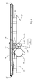
- the air intake device 100 has an air duct 20 which is such that from the fan 25 via the first suction chamber 26, the intake manifold 29 and the second suction chamber 27 air (indicated by the arrows with the reference numerals 5 and 10) through the transverse grooves 23 of the toothed belt 40 is sucked (Fig. 1 to 3).
- the timing belt 40 is open at the top, that is, when no sheet 1, 2, 3 rests, the air is sucked from the environment directly on the suction slot 30.
- the negative pressure which sets in the transverse grooves 23 of the toothed belt 40 and thus determines the pressing force F P now depends primarily on the power of the blower 25 and the pressure drop P V , in this case in the first line by the width of the throttle gap 21 is determined. There is also a small contribution to the negative pressure due to the dynamic proportion ⁇ / 2 * U 2 .
- the air duct 20 is designed so that the air after flowing through the transverse grooves 23 of the Timing belt 40 can flow as low loss. This is achieved by the fact that the Inlet 29 have the largest possible inner diameter and also the Suction chambers 26, 27. The diameters are limited by the existing Installation spaces.
- This bypass opening 28 causes movement of the Bypass throttle 32 in the direction indicated by the double arrow P3 that the Blower 25 despite high speeds only little air from the range of the toothed belt 40th sucks and sucks most of the air directly through the bypass port 28, depending on Size of the still uncovered bypass opening 28.
- the present construction also gives the possibility of the air duct 20 in three To be able to subdivide areas in which the negative pressures are different. This is achieved by the fact that the cross sections of the intake manifold 29 at a suitable location z. B. to be changed by throttle plates, not shown. Another subdivision into two or more areas is also conceivable.
- the toothed belt 40 has teeth 42 with a rounded surface 44.
- the bearing surface of the sheet 1, 2, 3 is reduced on the timing belt 40, and correspondingly the area over which the negative pressure on the sheet 1, 2, 3 attacks, increases.
- the contact with the arch is more gentle due to the curves than would be the case with sharp-edged corners.
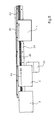
- the toothed belt pulley 45 rotating in the direction indicated by the arrow P2 drives the toothed belt 40, so that a running direction of the sheets 1, 2, 3 moves from an upstream feeder, not shown, to a downstream one (not shown) Folder results.
- the toothed belt 40 is guided by deflection rollers 46, 47, the tension roller 48 and the toothed belt groove in the carrier.
- the toothed belt groove is such that the teeth end up flush with the support surface. If the air intake device 100 is in operation, the vacuum-loaded toothed belt 40 takes over the sheet 1, 2, 3 from the feeder and transfers it to the folding unit after passing through the alignment line.
- a plurality of sheets 1, 2, 3 shown by the ruler 50 side be aligned.
- the sheets 1, 2, 3 have a direction of movement with the arrow P4 is marked, and with the direction of the toothed belt 40th matches.
- the ruler 50 With the ruler 50 at right angles to the following folder stands and the timing belt 40 is guided at an angle to the ruler 50, the moves Sheet 1, 2, 3 straight to the ruler 50 to.
- the sheet 1, 2, 3, the ruler 50th touched there is a relative movement between the sheet 1, 2, 3 and the timing belt 40 perpendicular to the sheet run.
- the sheet 1, 2, 3 depends on the ruler 50 and is thus aligned to the folding unit in a direction of movement, which now parallel to the ruler 50 and is marked with arrow P5 in Fig. 5, passed.
- the control means throttle 31 and bypass throttle 32 are controlled by a controller 33 controlled.
- This controller 33 also controls the speed of the fan 25.
- Die Control quantities for this purpose are from the controller 33 via look-up tables for looked at different parameters or by a suitable algorithm Reason the different parameters calculated or other, comparable, the Detected specialist known methods.
- the parameters are in particular around the grammage of the sheet 1, 2, 3, the width of the sheet 1, 2, 3, the static Charge of the sheet 1, 2, 3, the state of the ink, the roughness of the Arc surface, the amount of powder from the printing process, the grain direction Wide lane and narrow lane of the arch 1, 2, 3, the bow speed, the distance from sheet 1, 2, 3 to sheet 1, 2, 3 and the suction length through the suction wheel at the bow is generated, this list is not exhaustive.
- Including control of the fan 25 includes that the operator as possible has little adjustment effort and the values to be set readily determined can be, so z. B. not based on experience. In terms of Automation of folding machines, therefore, the settings are automated, let Save and can be retrieved during a repeat job again. Alles Incidentally, this does not apply to the otherwise used ball bars.
- control means are designed such that a Manual intervention in the control is possible, such as manual opening or Close the throttle 31 or bypass throttle 32 to the less important To include parameters manually.
- the negative pressure is in the present construction via a PWM signal (Pulse width modulation) controlled by an algorithm based on the grammage and the sheet width is generated.
- PWM signal Pulse width modulation
- the PWM signal of the blower manually readjusted.
Landscapes
- Delivering By Means Of Belts And Rollers (AREA)
- Registering Or Overturning Sheets (AREA)
- Attitude Control For Articles On Conveyors (AREA)
- Pile Receivers (AREA)
Abstract
Description
- Fig. 1
- eine Ansicht der Luftansaugeinrichtung im Schnitt;
- Fig. 2
- das Förderband im Schnitt;
- Fig. 3
- eine vergrößerte Ansicht von einem Detail der Luftansaugeinrichtung im Schnitt, im Bereich der Quernuten des Förderbandes;
- Fig. 4
- eine Seitenansicht der Luftansaugeinrichtung;
- Fig. 5
- eine Draufsicht der Luftansaugeinrichtung mit einlaufenden Bogen.
Wenn der Zahnriemen 40 nach oben hin offen ist, d.h. wenn kein Bogen 1, 2, 3 aufliegt, wird die Luft aus der Umgebung direkt am Absaugschlitz 30 angesaugt.
Der Unterdruck der sich in den Quernuten 23 des Zahnriemens 40 einstellt und somit die Andruckkraft FP bestimmt, hängt nun in erster Linie von der Leistung des Gebläses 25 ab und dem Druckverlust PV, der in diesem Fall in erster Line durch die Breite des Drosselspalts 21 bestimmt wird. Hinzu kommt noch ein kleiner Beitrag zum Unterdruck durch den dynamischen Anteil ρ/2*U2.
Die sich in der mit dem Pfeil P2 gekennzeichneten Richtung drehende Zahnriemenscheibe 45 (vergleiche Fig. 4) treibt den Zahnriemen 40 an, so dass sich eine Laufrichtung der Bogen 1, 2, 3 von einem nicht gezeigten vorgelagerten Anleger hin zu einem nachgelagerten, nicht gezeigten Falzwerk ergibt. Der Zahnriemen 40 wird durch Umlenkrollen 46, 47, die Spannrolle 48 und die Zahnriemen-Nut im Träger geführt. Die Zahnriemen-Nut ist derart beschaffen, dass die Zähne oben gerade mit der Auflagefläche abschließen. Ist die Luftansaugeinrichtung 100 in Betrieb, übernimmt der unterdruckbeaufschlagte Zahnriemen 40 den Bogen 1, 2, 3 vom Anleger und übergibt ihn nach durchlaufen der Ausrichtstrecke an das Falzwerk.
- 1, 2, 3
- Bogen
- 5
- einströmende Luft
- 10
- Luftstrom durch die Vorrichtung
- 20
- Luftkanal
- 21
- Drosselspalt
- 22
- Spalt
- 23
- Quernut
- 24
- Abdeckblech
- 25
- Gebläse
- 26
- erste Saugkammer
- 27
- zweite Saugkammer
- 28
- Bypassöffnung
- 29
- Ansaugstutzen
- 30
- Absaugschlitz
- 31
- Drosselklappe
- 32
- Bypassdrossel
- 33
- Steuerung
- 40
- Zahnriemen
- 42
- Zahn
- 44
- Zahnoberfläche
- 45
- Zahnriemenscheibe
- 46
- Umlenkrolle
- 47
- Umlenkrolle
- 48
- Spannrolle
- 50
- Lineal
- 100
- Luftansaugvorrichtung
- P1
- Transportrichtung der Bogen
- P2
- Drehrichtung der Zahnriemenscheibe
- P3
- Bewegungsrichtung der Bypassdrossel
- P4
- Bewegungsrichtung eines ausgerichteten Bogens
- P5
- Bewegungsrichtung eines unausgerichteten Bogens
Claims (12)
- Vorrichtung zum Fördern und gleichzeitigen Ausrichten von Bogen (1, 2, 3), mit einem Richtlineal (50) und mit mindestens einem in Bogenlaufrichtung leicht schräg zum Richtlineal (50) weisend angeordneten Förderband (40) und einer Luftansaugeinrichtung (100), wobei das Förderband (40) auf seiner den Bogen (1, 2, 3) tragenden Oberseite offene Quernuten (23) aufweist, und wobei das obere Trum des Förderbandes (40) in einem oben offenen Führungskanal läuft, und wobei die Quernuten (23) mit der Luftansaugeinrichtung (100) in Strömungsverbindung (20) stehen,
dadurch gekennzeichnet, dass Steuerungsmittel (31, 32, 33) vorgesehen sind, zur Steuerung der Luftzufuhr im Bereich der Quernuten (23). - Vorrichtung nach dem Anspruch 1,
dadurch gekennzeichnet, dass es sich bei dem Steuerungsmittel (31, 32, 33) wenigstens um eine Drosselklappe (31) handelt, die im Ansaugbereich der Luftzufuhr die Luftzufuhr vor den Quernuten (23) steuert. - Vorrichtung nach einem der Ansprüche 1 bis 2,
dadurch gekennzeichnet, dass es sich bei dem Steuerungsmittel (31, 32, 33) wenigstens um eine Bypassklappe (32) handelt, die eine Bypassöffnung (28) öffnet, durch den unter Umgehung des Bereichs der Quernuten (23) Umgebungsluft zu einem Gebläse (25) der Luftansaugeinrichtung (100) angesaugt wird. - Vorrichtung nach einem der Ansprüche 1 bis 3,
dadurch gekennzeichnet, dass es sich bei dem Steuerungsmittel (31, 32, 33) wenigstens um eine elektronische Steuerung (33) handelt, die die Leistung der Luftansaugeinrichtung (100) in Abhängigkeit von Kenngrößen der Bogen (1, 2, 3) ansteuert, insbesondere durch die Regelung der Drehzahl eines Gebläses (25) der Luftansaugvorrichtung (100). - Vorrichtung nach dem Anspruch 4,
dadurch gekennzeichnet, dass die elektronische Steuerung (33) zudem den Öffnungszustand der Drosselklappe (31) und / oder der Bypassklappe (32) steuert. - Vorrichtung nach einem der Ansprüche 4 bis 5,
dadurch gekennzeichnet, dass in der elektronische Steuerung (33) eine Steuerungsvorschrift für die elektronische Steuerung (33) der übrigen Steuerungsmittel (31, 32, 33) hinterlegt ist, wobei die Steuerungsvorschrift insbesondere auf empirischen Daten beruht. - Vorrichtung nach dem Anspruch 6,
dadurch gekennzeichnet, dass die Steuerungsvorschrift anhand von an der elektronischen Steuerung (33) eingebbaren Werten bezüglich Grammatur und Breite der Bogen (1, 2, 3) die übrigen Steuerungsmittel (31, 32, 33) steuert. - Vorrichtung nach dem Anspruch 7,
dadurch gekennzeichnet, dass die Steuerungsvorschrift zusätzlich wenigstens einen der folgenden Parameter zur Steuerung der übrigen Steuerungsmittel (31, 32, 33) berücksichtigt: statische Aufladung des Bogen (1, 2, 3), Zustand der Druckfarbe, Rauhigkeit der Bogenoberfläche, Menge eines Puders aus dem Druckprozess, Faserrichtung wie Breitbahn und Schmalbahn des Bogens (1, 2, 3), Bogengeschwindigkeit, Abstand von Bogen (1, 2, 3) zu Bogen(1, 2, 3), Sauglänge eines Saugrades am Anleger. - Vorrichtung nach einem der Ansprüche 1 bis 8,
dadurch gekennzeichnet, dass die Oberseite des Führungskanals im Wesentlichen auf gleicher Höhe mit der Oberseite des Förderbandes (40) liegt. - Vorrichtung nach einem der Ansprüche 1 bis 9,
dadurch gekennzeichnet, dass der Saugluftkanal (20) hinter den Quernuten (23) sich soweit verbreitert, dass er dadurch einen möglichst geringen Strömungswiderstand aufweist. - Vorrichtung nach einem der Ansprüche 1 bis 10,
dadurch gekennzeichnet, dass die Luftansaugeinrichtung (100) einschließlich des Gebläses (25) zum Zweck einer Formateinstellung verfahrbar ist. - Vorrichtung nach einem der Ansprüche 1 bis 11,
dadurch gekennzeichnet, dass es sich bei dem Förderband (40) um einen Zahnriemen (40) handelt, wobei der Zahnriemen (40) insbesondere oben abgerundete Zähne (42) aufweist.
Applications Claiming Priority (2)
| Application Number | Priority Date | Filing Date | Title |
|---|---|---|---|
| DE102004022141A DE102004022141A1 (de) | 2004-05-05 | 2004-05-05 | Vorrichtung zum Fördern und gleichzeitigen Ausrichten von Bogen |
| DE102004022141 | 2004-05-05 |
Publications (3)
| Publication Number | Publication Date |
|---|---|
| EP1593628A2 true EP1593628A2 (de) | 2005-11-09 |
| EP1593628A3 EP1593628A3 (de) | 2008-10-08 |
| EP1593628B1 EP1593628B1 (de) | 2009-12-02 |
Family
ID=34939497
Family Applications (1)
| Application Number | Title | Priority Date | Filing Date |
|---|---|---|---|
| EP05103353A Expired - Lifetime EP1593628B1 (de) | 2004-05-05 | 2005-04-26 | Vorrichtung zum Fördern und gleichzeitigen Ausrichten von Bogen |
Country Status (6)
| Country | Link |
|---|---|
| US (1) | US7374164B2 (de) |
| EP (1) | EP1593628B1 (de) |
| CN (1) | CN100572235C (de) |
| AT (1) | ATE450464T1 (de) |
| DE (2) | DE102004022141A1 (de) |
| PT (1) | PT1593628E (de) |
Families Citing this family (13)
| Publication number | Priority date | Publication date | Assignee | Title |
|---|---|---|---|---|
| US7894765B2 (en) * | 2006-12-18 | 2011-02-22 | Canon Kabushiki Kaisha | Sheet processing apparatus and image forming apparatus for controlling a folding operation |
| DE102010049057A1 (de) | 2010-10-20 | 2012-04-26 | Heidelberger Druckmaschinen Ag | Bogenfalzmaschine und Verfahren zum Betreiben einer Falzmaschine |
| DE102012004239B4 (de) | 2011-03-18 | 2023-12-21 | Heidelberger Druckmaschinen Ag | Transporteinrichtung für Bogen |
| DE102012019051B4 (de) | 2011-10-17 | 2022-08-11 | Heidelberger Druckmaschinen Ag | Transportvorrichtung für Bogen mit obenliegender Blasluftkammer |
| DE102011116365A1 (de) | 2011-10-19 | 2013-04-25 | Heidelberger Druckmaschinen Aktiengesellschaft | Bogenbearbeitungsmaschine mit Bogenanleger mit Saugbandmodul |
| JP5842679B2 (ja) | 2012-03-09 | 2016-01-13 | 株式会社リコー | 記録媒体排出装置および画像形成装置 |
| DE102013008298A1 (de) | 2012-05-31 | 2013-12-05 | Heidelberger Druckmaschinen Ag | Transporteinrichtung für Bogen |
| EP2706029B1 (de) * | 2012-09-06 | 2019-01-16 | Heidelberger Druckmaschinen AG | Vorrichtung zum Ausrichten von Bogen mit Gelenkarmlagerung |
| US8915497B2 (en) * | 2013-01-04 | 2014-12-23 | Tamarack Products, Inc. | Method and apparatus for sheet and carton blank aligning using caster effect |
| DE102017208091B4 (de) * | 2017-05-15 | 2023-02-09 | Koenig & Bauer Ag | Bogenzuführvorrichtung für eine Druckmaschine |
| DE102017208090B4 (de) * | 2017-05-15 | 2024-03-21 | Koenig & Bauer Ag | Bogenzuführvorrichtung für eine Druckmaschine |
| US10569981B2 (en) * | 2018-03-29 | 2020-02-25 | Xerox Corporation | Active registration system utilizing forced air for edge registration |
| JP2022024724A (ja) * | 2020-07-28 | 2022-02-09 | パナソニックIpマネジメント株式会社 | 搬送装置 |
Family Cites Families (17)
| Publication number | Priority date | Publication date | Assignee | Title |
|---|---|---|---|---|
| GB885556A (en) * | 1960-04-06 | 1961-12-28 | Universal Corrugated Box Mach | Conveying equipment, more particularly for folded box blanks |
| DE1260378B (de) * | 1965-11-17 | 1968-02-01 | Marius Martin S A | Vorrichtung zum Foerdern von platten- oder blattfoermigen Gegenstaenden |
| DE3138481C2 (de) * | 1981-09-28 | 1984-05-10 | M.A.N.- Roland Druckmaschinen AG, 6050 Offenbach | Vorrichtung zum Fördern eines geschuppten Stroms von Papierbogen |
| DE3331662A1 (de) * | 1983-09-02 | 1985-03-28 | M.A.N.- Roland Druckmaschinen AG, 6050 Offenbach | Verfahren und vorrichtung zum passgenauen bogentransport in eine druckmaschine |
| DE3410029C1 (de) * | 1984-03-19 | 1985-08-22 | Maschinenbau Oppenweiler Binder GmbH & Co, 7155 Oppenweiler | Ausrichtetisch |
| DE3447331A1 (de) * | 1984-12-24 | 1986-06-26 | Mathias Bäuerle GmbH, 7742 ST. Georgen | Pneumatischer bogenanleger |
| DE3607882C1 (en) * | 1986-03-10 | 1987-04-02 | Oppenweiler Binder Gmbh Maschb | Alignment table |
| DD252173A1 (de) * | 1986-08-29 | 1987-12-09 | Polygraph Leipzig | Vorrichtung zum foerdern und ausrichten von bogen |
| DE3931995A1 (de) * | 1989-09-26 | 1991-04-04 | Heidelberger Druckmasch Ag | Vorrichtung zur luftsteuerung von anlegerblas- und anlegersaugluft bei bogenanlegern von druckmaschinen |
| DE4421918C1 (de) * | 1994-06-24 | 1995-09-21 | Guenter Mattka | Vorrichtung zum Fördern und gleichzeitigen Ausrichten von bogenförmigem Material, insbesondere aus Papier, Karton oder Folien |
| US5600906A (en) * | 1995-10-03 | 1997-02-11 | Jet Sew Technologies, Inc. | Automatic suction type transfer of limp material on conveyors |
| DE19625470A1 (de) * | 1996-06-26 | 1998-01-02 | Bielomatik Leuze & Co | Verfahren und Vorrichtung zur Förderung von Gegenständen |
| AUPO902797A0 (en) * | 1997-09-05 | 1997-10-02 | Cortronix Pty Ltd | A rotary blood pump with hydrodynamically suspended impeller |
| DE10213705C5 (de) * | 2001-04-26 | 2017-01-05 | Heidelberger Druckmaschinen Ag | Vorrichtung zum Fördern eines Bogenstroms von einem Bogenstapel zu einer bogenverarbeitenden Maschine |
| SE0501382L (sv) * | 2005-06-17 | 2006-06-13 | Itt Mfg Enterprises Inc | Pump för pumpning av förorenad vätska |
| DE102005054027A1 (de) * | 2005-11-10 | 2007-05-16 | Pierburg Gmbh | Fluidpumpe |
| DE102006040130A1 (de) * | 2006-08-26 | 2008-02-28 | Ksb Aktiengesellschaft | Förderpumpe |
-
2004
- 2004-05-05 DE DE102004022141A patent/DE102004022141A1/de not_active Withdrawn
-
2005
- 2005-04-26 EP EP05103353A patent/EP1593628B1/de not_active Expired - Lifetime
- 2005-04-26 PT PT05103353T patent/PT1593628E/pt unknown
- 2005-04-26 DE DE502005008603T patent/DE502005008603D1/de not_active Expired - Lifetime
- 2005-04-26 AT AT05103353T patent/ATE450464T1/de not_active IP Right Cessation
- 2005-04-30 CN CNB2005100922679A patent/CN100572235C/zh not_active Expired - Fee Related
- 2005-05-05 US US11/123,457 patent/US7374164B2/en not_active Expired - Fee Related
Also Published As
| Publication number | Publication date |
|---|---|
| CN1736835A (zh) | 2006-02-22 |
| EP1593628A3 (de) | 2008-10-08 |
| US20050248081A1 (en) | 2005-11-10 |
| US7374164B2 (en) | 2008-05-20 |
| DE502005008603D1 (de) | 2010-01-14 |
| ATE450464T1 (de) | 2009-12-15 |
| PT1593628E (pt) | 2010-03-08 |
| CN100572235C (zh) | 2009-12-23 |
| EP1593628B1 (de) | 2009-12-02 |
| DE102004022141A1 (de) | 2005-11-24 |
Similar Documents
| Publication | Publication Date | Title |
|---|---|---|
| EP0454011B1 (de) | Vorrichtung zum Fördern eines insbesondere geschuppten Stroms von Bogen | |
| EP0134526B1 (de) | Verfahren und Vorrichtung zum passgenauen Bogentransport in eine Druckmaschine | |
| EP1593628B1 (de) | Vorrichtung zum Fördern und gleichzeitigen Ausrichten von Bogen | |
| EP0888992B1 (de) | Anlegetisch zum taktmässigen Fördern von Bogen zu einer Bogen verarbeitenden Maschine | |
| DE4242730A1 (de) | Bogenausleger einer Druckmaschine | |
| EP1516838A9 (de) | Vorrichtung zur Verarbeitung von Stapeln aus elektrostatisch aufladbaren Flachteilen | |
| DE19523076C2 (de) | Vorrichtung zur Erzielung einer einwandfreien Auflage eines Bedruckstoffs in einer Druckmaschine | |
| DE4213387C2 (de) | Papieraustrageinrichtung | |
| EP0899228B1 (de) | Luftpolsterführung | |
| EP2517995B1 (de) | Falzmaschine mit Transportvorrichtung | |
| DE102004030277B4 (de) | Vorrichtung zur Förderung von Bogen durch eine drucktechnische Maschine | |
| DE102012206847A1 (de) | Saugfördervorrichtung zum Transport von Flachteilen | |
| DE19916342A1 (de) | Druckbogenumlenkkeil mit Luftauslässen | |
| DE4424483A1 (de) | Ausleger einer bogenverarbeitenden Maschine | |
| DE3324495A1 (de) | Stapelvorrichtung fuer zuschnitte | |
| EP1588967B1 (de) | Fördertisch | |
| EP1016610A2 (de) | Vorrichtung zum Transport von einander zu überlappenden Bögen, insbesondere Papierbögen | |
| DE4421918C1 (de) | Vorrichtung zum Fördern und gleichzeitigen Ausrichten von bogenförmigem Material, insbesondere aus Papier, Karton oder Folien | |
| DE10112759A1 (de) | Verfahren und Vorrichtung zur berührungslosen Führung von Bogen | |
| DE10134836B4 (de) | Ausleger für eine bogenverarbeitende Maschine, insbesondere für eine Bogendruckmaschine | |
| EP1414728B1 (de) | Vorrichtung zur ausrichtung von in einer lage übereinander angeordneten bogen | |
| DE1931208B2 (de) | Vorrichtung zum Fördern und Ablegen von Bögen aus Papier und anderem blattförmigen Material in Stapeln | |
| DE9004967U1 (de) | Vorrichtung zum Fördern eines insbesondere geschuppten Stroms von Bogen | |
| DE102017208091B4 (de) | Bogenzuführvorrichtung für eine Druckmaschine | |
| DE102004060031B4 (de) | Leiteinrichtung zum Leiten von Materialbögen oder Materialbahnen |
Legal Events
| Date | Code | Title | Description |
|---|---|---|---|
| PUAI | Public reference made under article 153(3) epc to a published international application that has entered the european phase |
Free format text: ORIGINAL CODE: 0009012 |
|
| AK | Designated contracting states |
Kind code of ref document: A2 Designated state(s): AT BE BG CH CY CZ DE DK EE ES FI FR GB GR HU IE IS IT LI LT LU MC NL PL PT RO SE SI SK TR |
|
| AX | Request for extension of the european patent |
Extension state: AL BA HR LV MK YU |
|
| 17P | Request for examination filed |
Effective date: 20070510 |
|
| PUAL | Search report despatched |
Free format text: ORIGINAL CODE: 0009013 |
|
| AK | Designated contracting states |
Kind code of ref document: A3 Designated state(s): AT BE BG CH CY CZ DE DK EE ES FI FR GB GR HU IE IS IT LI LT LU MC NL PL PT RO SE SI SK TR |
|
| AX | Request for extension of the european patent |
Extension state: AL BA HR LV MK YU |
|
| AKX | Designation fees paid |
Designated state(s): AT BE BG CH CY CZ DE DK EE ES FI FR GB GR HU IE IS IT LI LT LU MC NL PL PT RO SE SI SK TR |
|
| GRAP | Despatch of communication of intention to grant a patent |
Free format text: ORIGINAL CODE: EPIDOSNIGR1 |
|
| GRAS | Grant fee paid |
Free format text: ORIGINAL CODE: EPIDOSNIGR3 |
|
| GRAA | (expected) grant |
Free format text: ORIGINAL CODE: 0009210 |
|
| AK | Designated contracting states |
Kind code of ref document: B1 Designated state(s): AT BE BG CH CY CZ DE DK EE ES FI FR GB GR HU IE IS IT LI LT LU MC NL PL PT RO SE SI SK TR |
|
| REG | Reference to a national code |
Ref country code: GB Ref legal event code: FG4D Free format text: NOT ENGLISH |
|
| REG | Reference to a national code |
Ref country code: CH Ref legal event code: EP |
|
| REG | Reference to a national code |
Ref country code: IE Ref legal event code: FG4D |
|
| REF | Corresponds to: |
Ref document number: 502005008603 Country of ref document: DE Date of ref document: 20100114 Kind code of ref document: P |
|
| REG | Reference to a national code |
Ref country code: PT Ref legal event code: SC4A Free format text: AVAILABILITY OF NATIONAL TRANSLATION Effective date: 20100301 |
|
| REG | Reference to a national code |
Ref country code: NL Ref legal event code: VDEP Effective date: 20091202 |
|
| PG25 | Lapsed in a contracting state [announced via postgrant information from national office to epo] |
Ref country code: FI Free format text: LAPSE BECAUSE OF FAILURE TO SUBMIT A TRANSLATION OF THE DESCRIPTION OR TO PAY THE FEE WITHIN THE PRESCRIBED TIME-LIMIT Effective date: 20091202 Ref country code: LT Free format text: LAPSE BECAUSE OF FAILURE TO SUBMIT A TRANSLATION OF THE DESCRIPTION OR TO PAY THE FEE WITHIN THE PRESCRIBED TIME-LIMIT Effective date: 20091202 Ref country code: SE Free format text: LAPSE BECAUSE OF FAILURE TO SUBMIT A TRANSLATION OF THE DESCRIPTION OR TO PAY THE FEE WITHIN THE PRESCRIBED TIME-LIMIT Effective date: 20091202 |
|
| LTIE | Lt: invalidation of european patent or patent extension |
Effective date: 20091202 |
|
| PG25 | Lapsed in a contracting state [announced via postgrant information from national office to epo] |
Ref country code: PL Free format text: LAPSE BECAUSE OF FAILURE TO SUBMIT A TRANSLATION OF THE DESCRIPTION OR TO PAY THE FEE WITHIN THE PRESCRIBED TIME-LIMIT Effective date: 20091202 Ref country code: CY Free format text: LAPSE BECAUSE OF FAILURE TO SUBMIT A TRANSLATION OF THE DESCRIPTION OR TO PAY THE FEE WITHIN THE PRESCRIBED TIME-LIMIT Effective date: 20091202 Ref country code: SI Free format text: LAPSE BECAUSE OF FAILURE TO SUBMIT A TRANSLATION OF THE DESCRIPTION OR TO PAY THE FEE WITHIN THE PRESCRIBED TIME-LIMIT Effective date: 20091202 |
|
| REG | Reference to a national code |
Ref country code: IE Ref legal event code: FD4D |
|
| PG25 | Lapsed in a contracting state [announced via postgrant information from national office to epo] |
Ref country code: BG Free format text: LAPSE BECAUSE OF FAILURE TO SUBMIT A TRANSLATION OF THE DESCRIPTION OR TO PAY THE FEE WITHIN THE PRESCRIBED TIME-LIMIT Effective date: 20100302 Ref country code: EE Free format text: LAPSE BECAUSE OF FAILURE TO SUBMIT A TRANSLATION OF THE DESCRIPTION OR TO PAY THE FEE WITHIN THE PRESCRIBED TIME-LIMIT Effective date: 20091202 Ref country code: ES Free format text: LAPSE BECAUSE OF FAILURE TO SUBMIT A TRANSLATION OF THE DESCRIPTION OR TO PAY THE FEE WITHIN THE PRESCRIBED TIME-LIMIT Effective date: 20100313 Ref country code: NL Free format text: LAPSE BECAUSE OF FAILURE TO SUBMIT A TRANSLATION OF THE DESCRIPTION OR TO PAY THE FEE WITHIN THE PRESCRIBED TIME-LIMIT Effective date: 20091202 Ref country code: IE Free format text: LAPSE BECAUSE OF FAILURE TO SUBMIT A TRANSLATION OF THE DESCRIPTION OR TO PAY THE FEE WITHIN THE PRESCRIBED TIME-LIMIT Effective date: 20091202 Ref country code: RO Free format text: LAPSE BECAUSE OF FAILURE TO SUBMIT A TRANSLATION OF THE DESCRIPTION OR TO PAY THE FEE WITHIN THE PRESCRIBED TIME-LIMIT Effective date: 20091202 Ref country code: IS Free format text: LAPSE BECAUSE OF FAILURE TO SUBMIT A TRANSLATION OF THE DESCRIPTION OR TO PAY THE FEE WITHIN THE PRESCRIBED TIME-LIMIT Effective date: 20100402 |
|
| PG25 | Lapsed in a contracting state [announced via postgrant information from national office to epo] |
Ref country code: SK Free format text: LAPSE BECAUSE OF FAILURE TO SUBMIT A TRANSLATION OF THE DESCRIPTION OR TO PAY THE FEE WITHIN THE PRESCRIBED TIME-LIMIT Effective date: 20091202 Ref country code: CZ Free format text: LAPSE BECAUSE OF FAILURE TO SUBMIT A TRANSLATION OF THE DESCRIPTION OR TO PAY THE FEE WITHIN THE PRESCRIBED TIME-LIMIT Effective date: 20091202 |
|
| PLBE | No opposition filed within time limit |
Free format text: ORIGINAL CODE: 0009261 |
|
| STAA | Information on the status of an ep patent application or granted ep patent |
Free format text: STATUS: NO OPPOSITION FILED WITHIN TIME LIMIT |
|
| PG25 | Lapsed in a contracting state [announced via postgrant information from national office to epo] |
Ref country code: GR Free format text: LAPSE BECAUSE OF FAILURE TO SUBMIT A TRANSLATION OF THE DESCRIPTION OR TO PAY THE FEE WITHIN THE PRESCRIBED TIME-LIMIT Effective date: 20100303 |
|
| BERE | Be: lapsed |
Owner name: HEIDELBERGER DRUCKMASCHINEN A.G. Effective date: 20100430 |
|
| 26N | No opposition filed |
Effective date: 20100903 |
|
| PG25 | Lapsed in a contracting state [announced via postgrant information from national office to epo] |
Ref country code: MC Free format text: LAPSE BECAUSE OF NON-PAYMENT OF DUE FEES Effective date: 20100430 |
|
| REG | Reference to a national code |
Ref country code: CH Ref legal event code: PL |
|
| GBPC | Gb: european patent ceased through non-payment of renewal fee |
Effective date: 20100426 |
|
| REG | Reference to a national code |
Ref country code: FR Ref legal event code: ST Effective date: 20101230 |
|
| PG25 | Lapsed in a contracting state [announced via postgrant information from national office to epo] |
Ref country code: DK Free format text: LAPSE BECAUSE OF FAILURE TO SUBMIT A TRANSLATION OF THE DESCRIPTION OR TO PAY THE FEE WITHIN THE PRESCRIBED TIME-LIMIT Effective date: 20091202 |
|
| PG25 | Lapsed in a contracting state [announced via postgrant information from national office to epo] |
Ref country code: CH Free format text: LAPSE BECAUSE OF NON-PAYMENT OF DUE FEES Effective date: 20100430 Ref country code: LI Free format text: LAPSE BECAUSE OF NON-PAYMENT OF DUE FEES Effective date: 20100430 |
|
| PG25 | Lapsed in a contracting state [announced via postgrant information from national office to epo] |
Ref country code: BE Free format text: LAPSE BECAUSE OF NON-PAYMENT OF DUE FEES Effective date: 20100430 Ref country code: GB Free format text: LAPSE BECAUSE OF NON-PAYMENT OF DUE FEES Effective date: 20100426 |
|
| PG25 | Lapsed in a contracting state [announced via postgrant information from national office to epo] |
Ref country code: AT Free format text: LAPSE BECAUSE OF NON-PAYMENT OF DUE FEES Effective date: 20100426 |
|
| PG25 | Lapsed in a contracting state [announced via postgrant information from national office to epo] |
Ref country code: FR Free format text: LAPSE BECAUSE OF NON-PAYMENT OF DUE FEES Effective date: 20100430 |
|
| PG25 | Lapsed in a contracting state [announced via postgrant information from national office to epo] |
Ref country code: LU Free format text: LAPSE BECAUSE OF NON-PAYMENT OF DUE FEES Effective date: 20100426 Ref country code: HU Free format text: LAPSE BECAUSE OF FAILURE TO SUBMIT A TRANSLATION OF THE DESCRIPTION OR TO PAY THE FEE WITHIN THE PRESCRIBED TIME-LIMIT Effective date: 20100603 |
|
| PG25 | Lapsed in a contracting state [announced via postgrant information from national office to epo] |
Ref country code: TR Free format text: LAPSE BECAUSE OF FAILURE TO SUBMIT A TRANSLATION OF THE DESCRIPTION OR TO PAY THE FEE WITHIN THE PRESCRIBED TIME-LIMIT Effective date: 20091202 |
|
| PGFP | Annual fee paid to national office [announced via postgrant information from national office to epo] |
Ref country code: IT Payment date: 20140419 Year of fee payment: 10 Ref country code: PT Payment date: 20140331 Year of fee payment: 10 |
|
| REG | Reference to a national code |
Ref country code: PT Ref legal event code: MM4A Free format text: LAPSE DUE TO NON-PAYMENT OF FEES Effective date: 20151026 |
|
| PG25 | Lapsed in a contracting state [announced via postgrant information from national office to epo] |
Ref country code: IT Free format text: LAPSE BECAUSE OF NON-PAYMENT OF DUE FEES Effective date: 20150426 |
|
| PG25 | Lapsed in a contracting state [announced via postgrant information from national office to epo] |
Ref country code: PT Free format text: LAPSE BECAUSE OF NON-PAYMENT OF DUE FEES Effective date: 20151026 |
|
| P01 | Opt-out of the competence of the unified patent court (upc) registered |
Effective date: 20230425 |
|
| PGFP | Annual fee paid to national office [announced via postgrant information from national office to epo] |
Ref country code: DE Payment date: 20240430 Year of fee payment: 20 |
|
| REG | Reference to a national code |
Ref country code: DE Ref legal event code: R071 Ref document number: 502005008603 Country of ref document: DE |