EP1593644A2 - Chariot de manutention avec un agencement piston-cylindre et un palier de cylindre amélioré - Google Patents
Chariot de manutention avec un agencement piston-cylindre et un palier de cylindre amélioré Download PDFInfo
- Publication number
- EP1593644A2 EP1593644A2 EP05009845A EP05009845A EP1593644A2 EP 1593644 A2 EP1593644 A2 EP 1593644A2 EP 05009845 A EP05009845 A EP 05009845A EP 05009845 A EP05009845 A EP 05009845A EP 1593644 A2 EP1593644 A2 EP 1593644A2
- Authority
- EP
- European Patent Office
- Prior art keywords
- cylinder
- bearing
- component
- piston
- truck according
- Prior art date
- Legal status (The legal status is an assumption and is not a legal conclusion. Google has not performed a legal analysis and makes no representation as to the accuracy of the status listed.)
- Granted
Links
Images
Classifications
-
- B—PERFORMING OPERATIONS; TRANSPORTING
- B66—HOISTING; LIFTING; HAULING
- B66F—HOISTING, LIFTING, HAULING OR PUSHING, NOT OTHERWISE PROVIDED FOR, e.g. DEVICES WHICH APPLY A LIFTING OR PUSHING FORCE DIRECTLY TO THE SURFACE OF A LOAD
- B66F9/00—Devices for lifting or lowering bulky or heavy goods for loading or unloading purposes
- B66F9/06—Devices for lifting or lowering bulky or heavy goods for loading or unloading purposes movable, with their loads, on wheels or the like, e.g. fork-lift trucks
- B66F9/075—Constructional features or details
- B66F9/20—Means for actuating or controlling masts, platforms, or forks
- B66F9/22—Hydraulic devices or systems
-
- B—PERFORMING OPERATIONS; TRANSPORTING
- B66—HOISTING; LIFTING; HAULING
- B66F—HOISTING, LIFTING, HAULING OR PUSHING, NOT OTHERWISE PROVIDED FOR, e.g. DEVICES WHICH APPLY A LIFTING OR PUSHING FORCE DIRECTLY TO THE SURFACE OF A LOAD
- B66F9/00—Devices for lifting or lowering bulky or heavy goods for loading or unloading purposes
- B66F9/06—Devices for lifting or lowering bulky or heavy goods for loading or unloading purposes movable, with their loads, on wheels or the like, e.g. fork-lift trucks
- B66F9/075—Constructional features or details
- B66F9/08—Masts; Guides; Chains
Definitions
- the present invention relates to an industrial truck with a piston-cylinder arrangement, comprising a cylinder and a retractable therefrom and in these retractable piston, as a drive and / or leadership a first component for movement relative to a second component, in particular as a drive of components of a mast, wherein the piston with a component assigned to it: first or second component, for power transmission coupled and wherein the cylinder on a cylinder bearing the other, the cylinder associated component stored and the Power transmission is coupled with this.
- piston-cylinder arrangements as drives and / or as a guide of an extension and a retraction movement used by lifting frame relative to truck frame fixed stands.
- the cylinder In order to achieve the most stable, load-bearing structure of a mast on the To obtain the truck, the cylinder is usually at least one Bearing as rigid as possible connected to the component stored him.
- misalignment means that piston longitudinal axis and cylinder longitudinal axis are not ideally coaxial, but in orthogonal to the cylinder longitudinal axis direction Offset offset slightly to each other and / or to a tilted slightly to the cylinder longitudinal axis orthogonal axis of rotation are. Such misalignments affect especially at far from the Cylinder extended piston, since the piston through the more accurate The cylinder can be guided, the longer the remaining in the cylinder Piston line is.
- Object of the present invention is therefore an industrial truck of the above specify type, in which a cylinder of a piston-cylinder assembly bearing truck component is less heavily loaded is.
- the cylinder can a compensation movement in a direction in which form or / and position deviations from the ideal shape or ideal position, such as misalignment between Pistons and cylinders are reduced, which also makes one in the field the piston opening of the cylinder on this exerted support torque decreases.
- This support torque is proportional in its amount to the amount of misalignment.
- the relative amount of shape and / or Position inaccuracies is reduced by a compensatory movement, such as it is made possible by the cylinder bearing according to the invention.
- the cylinder will be driven by him on the extended Piston-acting support torque, move in one direction, in which this applied to him supporting moment becomes smaller, so that the truck with the movably mounted cylinder in certain Borders represents a self-optimizing system.
- a separate controller to move the cylinder in a suitable direction is not required.
- the piston-cylinder arrangement is preferably a hydraulic one Drive suitable for lifting and / or lowering large loads is.
- the cylinder a closed longitudinal end and a longitudinal end with a piston opening on, wherein the cylinder bearing for the advantageous avoidance of excessive Cylinder deformation of the cylinder in the region of its longitudinal end with piston opening outsourced. Since a seal is provided at the piston opening, which the piston opening against entry of dirt into the cylinder chamber and possibly seals against leakage of hydraulic fluid, here is a Bermmuxness exists between piston and cylinder, by which forces be introduced from the piston into the cylinder. These forces can all the more less lead to deformation of the cylinder, the closer the cylinder bearing the piston opening is.
- the cylinder bearing is provided such that the piston opening does not exceed 20% of the total length of the Cylinder from the cylinder bearing is located away. Even more advantageous the removal of the piston opening does not account for 10% of the total length of the cylinder exceed. Particularly high forces can be achieved without appreciable deformation be absorbed by the cylinder when the piston opening is not further than 5% of the total length of the cylinder from the cylinder bearing is arranged.
- a movement of cylinder and cylinder bearing is relative to each other only a slight local relative movement in the area designated the cylinder bearing.
- the relative mobility of cylinders and cylinder bearing at the location of the cylinder storage do not exclude that the cylinder at a further bearing on the him assigned component or is mounted on another component.
- These another bearing point of the cylinder can be a floating bearing or even be a rigid depository, so that in the latter case the local Mobility of the cylinder in the range of the cylinder bearing discussed here relative to this, essentially by a deformation of the cylinder established.
- the cylinder is an offset of the cylinder longitudinal axis and this substantially parallel piston longitudinal axis by movement relative to the cylinder bearing can reduce
- the cylinder may be provided such that he relative to the cylinder bearing in at least one of the cylinder longitudinal axis direction orthogonal displacement direction, preferably in two to each other and to the cylinder longitudinal axis orthogonal directions of displacement, is displaceable.
- the cylinder may be used to reduce tilting of cylinder and piston longitudinal axis relative to each other also such be stored on the cylinder bearing that he relative to the cylinder bearing at least a tilt axis orthogonal to the cylinder longitudinal axis direction, preferably by two to each other and to the cylinder longitudinal axis direction orthogonal tilt axes, tiltable.
- a displacement be it now displaceability or tiltability in two mutually orthogonal Displacement directions or about two mutually orthogonal tilt axes provides a much greater possibility of error correction than a relocatability with only one orthogonal to the cylinder longitudinal axis direction Displacement direction or orthogonal to the cylinder longitudinal axis direction Tilting axis.
- a much needed compensation movement direction can be a displacement in only one direction of displacement or be advantageous to only one tilt axis, since this camp stiffer than a camp be formed with biaxial displacement possibility can.
- both surfaces are convexly curved or that one of the surfaces is flat.
- a tiltability or rotatability about at least two to each other and to the cylinder longitudinal axis direction orthogonal tilting axes can be obtained by Bearing surface and cylindrical surface in each case only one to the cylinder axis direction orthogonal curvature axis are convex curved that however, the axis of curvature of the support surface and the axis of curvature the cylindrical bearing surface are orthogonal to each other.
- Such solutions lead to very high surface pressures at the contact point of Bearing surface and cylinder bearing surface, which is less preferred.
- a very good option to compensate for manufacturing and / or assembly errors if at least one of the surfaces: bearing surface and cylinder bearing surface, at least in the area of the investment engagement by two to each other as also to the cylinder longitudinal axis orthogonal direction of curvature axes is convexly curved.
- the cylinder can relative to the cylinder bearing in any direction orthogonal to the cylinder longitudinal axis direction Tilting tilted or tilted.
- the bearing surface and / or the cylinder bearing surface at least be executed in sections barrel-shaped, so that different Kippachsen associated with different radii of curvature, what can lead to a preferential tilting axis.
- This may be desired, though a preferential compensation movement is known, because then still a Ausreteskippterrorism about an orthogonal to the preferred tilt axis Tilting is possible, but a difficult tilting always a Increasing the bearing stiffness allowed.
- An improved guidance of the relative tilting movement of cylinder and cylinder bearing can be obtained by having one of the surfaces: bearing surface and cylinder bearing surface, at least in the field of investment engagement at least one orthogonal to the cylinder longitudinal axis direction of curvature axis is convexly curved and the other surface: cylinder bearing surface and support surface, at least in the area of the investment engagement by at least a curvature axis orthogonal to the cylinder longitudinal axis direction is concavely curved.
- the Cylinder bearings are made very sturdy and thus durable when the Bearing surface and the cylinder bearing surface are curved so that they lie flat against each other.
- this embodiment namely between the Support surface and cylinder bearing surface acting surface pressure very low. It is the smaller, the larger the contact surface between support surface and cylinder bearing surface is.
- the support surface can be provided as desired on the cylinder be.
- the support surface extends along a peripheral portion of the cylinder.
- a higher bearing capacity of the bearing surface still results in very efficient use of the available space when the bearing surface surrounds the cylinder in the circumferential direction. This also allows a uniform force on a cylinder bearing To be supported force in the bearing surface.
- the cylinder a cylinder tube and a cylinder closure with piston opening include.
- the piston can be very easily introduced into the cylinder become.
- the cylinder lock due to its much lower Size compared to the cylinder tube easier and therefore cheaper is to edit, can advantageously be the bearing surface than the at least an at least partially curved surface on the cylinder closure be provided. This is especially true when the cylinder lock at least at the time before its connection to the cylinder tube is a separate component.
- a hydraulic Actuator acts, in which, depending on the desired Auskragin of the piston from the cylinder hydraulic fluid into the cylinder introduced or removed from this is from the point of view a simple installation of the hydraulic lines advantageous if the first component directly or indirectly fixed to a truck frame is connected and the second component relative to the first component movable is mounted, wherein the cylinder, the first frame-fixed component and the Piston is associated with the second movably mounted component.
- the distance changes the connection point for hydraulic fluid on the cylinder relative to Truck frame not, on the one hand the use of the shortest possible Hydraulic lines allows and on the other hand, the hydraulic lines do not walk through motion. It can even have stable pipes as hydraulic lines be used.
- the first component a stand and the second component to be a lifting frame.
- the first component can be a frame of a Budapesthubs and the second component a load carrier movably mounted thereon, in particular Fork carriage, his.
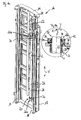
- a mast 10 comprising one on a frame a non-illustrated truck mounted stand 12 and one on this relative to the stator 12 movable lifting frame 14.
- Der Lift frame 14 is in guide rails 16 and 18 of the stator 12 for movement relative to the stator 12 in the direction of the double arrow V out.
- a piston 22 of the piston-cylinder assembly 20 is at its free Longitudinally fixed to a coupling point 24 of the lifting frame 14.
- the piston 22 can at the coupling point 24 both tensile and Exert pressure forces on the lifting frame 14.
- the piston-cylinder arrangement 20 comprises a cylinder 26 with a cylinder tube 28.
- the cylinder longitudinal axis L is parallel to the direction of movement V of the relative movement between lifting frame 14 and stand 12.
- the cylinder 26 is at its in FIG. 1a lower longitudinal end 26a held on the stand 12.
- the holder is made via a known floating bearing 30.
- the cylinder 26 relative to a surrounding cylindrical bearing 34 is mounted slightly movable.
- the cylindrical bearing 34 comprises in the example shown a metal plate with a hole which is penetrated by the cylinder 26.
- a cylinder closure 36 is inserted and with this firmly connected, such as by screwing or by plugging in and subsequent welding.
- a sealing arrangement 38 is provided, which surrounds the piston 22 along its circumference and prevents Dirt in the interior 40 of the cylinder 26 penetrates or hydraulic fluid out of this exit.
- the cylinder closure 36 has a bearing formation 42, which opposite the cylinder tube 28 projects radially outward, and that longitudinally the entire circumference of the cylinder closure 36.
- the piston 22nd and the cylinder 26 surrounding bearing formation 42 has a spherical cap, to the cylinder bearing 34 indicative bearing surface 42a.
- This support surface 42a is located on a part-spherical, concave cylinder bearing surface 34a of the cylindrical bearing 34.
- the cylinder 26 in the region of Contact point of support surface 42a and cylinder bearing surface 34a both order a first to the cylinder longitudinal axis L orthogonal axis X and a to the cylinder longitudinal axis L and the first axis X orthogonal second axis Y tilt.
- the addressed components can correspondingly be weaker be dimensioned or have the same dimensioning accordingly a longer life.
- the cylinder bearing 34 with a convex curved cylinder bearing surface and the cylinder 26 with a corresponding concave curved Support surface may be formed, however, can be a concave Form recess on the substantially flat cylinder bearing 34 easier as a corresponding convex curved cylinder bearing surface.
- At the cylinder 26 or particularly advantageous on the cylinder closure 36 may be a Convex curved bearing surface in a simple manner by turning getting produced.
Landscapes
- Engineering & Computer Science (AREA)
- Transportation (AREA)
- Structural Engineering (AREA)
- Civil Engineering (AREA)
- Life Sciences & Earth Sciences (AREA)
- Geology (AREA)
- Mechanical Engineering (AREA)
- Chemical & Material Sciences (AREA)
- Combustion & Propulsion (AREA)
- Forklifts And Lifting Vehicles (AREA)
- Actuator (AREA)
Applications Claiming Priority (2)
| Application Number | Priority Date | Filing Date | Title |
|---|---|---|---|
| DE102004022338 | 2004-05-06 | ||
| DE102004022338A DE102004022338A1 (de) | 2004-05-06 | 2004-05-06 | Flurförderzeug mit Kolben-Zylinder-Anordnung und verbesserter Zylinderlagerung |
Publications (3)
| Publication Number | Publication Date |
|---|---|
| EP1593644A2 true EP1593644A2 (fr) | 2005-11-09 |
| EP1593644A3 EP1593644A3 (fr) | 2011-09-07 |
| EP1593644B1 EP1593644B1 (fr) | 2013-06-26 |
Family
ID=34936184
Family Applications (1)
| Application Number | Title | Priority Date | Filing Date |
|---|---|---|---|
| EP05009845.8A Expired - Lifetime EP1593644B1 (fr) | 2004-05-06 | 2005-05-04 | Chariot de manutention avec un agencement piston-cylindre et un palier de cylindre amélioré |
Country Status (3)
| Country | Link |
|---|---|
| US (1) | US7340989B2 (fr) |
| EP (1) | EP1593644B1 (fr) |
| DE (1) | DE102004022338A1 (fr) |
Families Citing this family (5)
| Publication number | Priority date | Publication date | Assignee | Title |
|---|---|---|---|---|
| US10562746B2 (en) * | 2016-10-28 | 2020-02-18 | Hyster-Yale Group, Inc. | Mast support device |
| CN211110874U (zh) * | 2017-03-09 | 2020-07-28 | 海斯特-耶鲁集团有限公司 | 用于叉车的桅杆 |
| US10662047B2 (en) * | 2017-03-30 | 2020-05-26 | The Raymond Corporation | Extendable mast systems and methods for a material handling vehicle |
| CN110817753B (zh) * | 2019-11-27 | 2020-12-25 | 江苏航运职业技术学院 | 一种堆高机的门架滑动间隙控制结构 |
| US12600609B2 (en) | 2024-06-20 | 2026-04-14 | Mitsubishi Logisnext Americas Inc. | Hose supports for facilitating the assembly of masts for material handling vehicles and related methods |
Family Cites Families (12)
| Publication number | Priority date | Publication date | Assignee | Title |
|---|---|---|---|---|
| US3394778A (en) * | 1966-11-25 | 1968-07-30 | Eaton Yale & Towne | Lift truck mast assembly |
| DE1556601A1 (de) * | 1967-08-01 | 1970-03-05 | Linde Ag | Hublader mit einem ausfahrbaren Hubmast |
| US4183836A (en) * | 1978-02-06 | 1980-01-15 | E. I. Du Pont De Nemours And Company | Aqueous polyurethane dispersions |
| US4294572A (en) * | 1978-04-10 | 1981-10-13 | Pattison Jack E | Internal fluid communication system for power cylinders |
| DE2905084A1 (de) | 1979-02-10 | 1980-08-21 | Fluro Gelenklager Gmbh | Gelenkstangenkopf mit einseitig eingedrehtem kugelabschnitt |
| WO1981002290A1 (fr) * | 1980-02-07 | 1981-08-20 | Towmotor Corp | Cylindre hydraulique avec montage de cylindre spherique |
| US4430924A (en) * | 1981-08-28 | 1984-02-14 | Hydrowell Sa | Petroleum pumping unit |
| US4768606A (en) * | 1986-05-16 | 1988-09-06 | Linde Aktiengesellschaft | Hydraulic cylinder machine components |
| DE4400979C2 (de) | 1994-01-14 | 1997-07-24 | Gartner & Co J | Halterung zur Lagerung einer Platte |
| DE19519526A1 (de) * | 1995-05-27 | 1996-11-28 | Seele Gmbh | Halterung für Platten |
| US5934171A (en) * | 1997-07-24 | 1999-08-10 | Cymer, Inc. | Flexible mount for hydraulic/pneumatic cylinder and the like |
| JP3419265B2 (ja) * | 1997-08-28 | 2003-06-23 | 日産自動車株式会社 | 荷役具昇降用シリンダの取付構造 |
-
2004
- 2004-05-06 DE DE102004022338A patent/DE102004022338A1/de not_active Withdrawn
-
2005
- 2005-05-02 US US11/119,620 patent/US7340989B2/en not_active Expired - Fee Related
- 2005-05-04 EP EP05009845.8A patent/EP1593644B1/fr not_active Expired - Lifetime
Also Published As
| Publication number | Publication date |
|---|---|
| US20060027094A1 (en) | 2006-02-09 |
| DE102004022338A1 (de) | 2005-11-24 |
| EP1593644A3 (fr) | 2011-09-07 |
| EP1593644B1 (fr) | 2013-06-26 |
| US7340989B2 (en) | 2008-03-11 |
Similar Documents
| Publication | Publication Date | Title |
|---|---|---|
| DE3621421C1 (de) | Kolbenmaschine | |
| DE102009002613A1 (de) | Scherenhebebühne | |
| DE69812492T2 (de) | Trägerstruktur für Zylinder | |
| EP0256465B1 (fr) | Cylindre à flexion réglable | |
| EP2808289B1 (fr) | Mécanisme d'inclinaison d'un porte-fourche | |
| EP1593644A2 (fr) | Chariot de manutention avec un agencement piston-cylindre et un palier de cylindre amélioré | |
| EP2799283A2 (fr) | Véhicule de transport de charge doté d'un conteneur interchangeable et d'un appareil de levage pour un conteneur interchangeable | |
| DE19623580C2 (de) | Hubsäule | |
| DE19612091A1 (de) | Hubsäule | |
| EP4051621B1 (fr) | Dispositif d'entraînement | |
| DE102010020452B4 (de) | Schwenkbare Hubstütze | |
| EP0698575B1 (fr) | Elévateur, en particulier pour véhicules automobiles | |
| EP4087810B1 (fr) | Grue à tour à contrepoids réglable | |
| DE3907440C2 (fr) | ||
| DE2432908C3 (de) | Kippbarer Konverter | |
| DE102011006323A1 (de) | Keilgetriebe | |
| DE2812102A1 (de) | Hubgeruest fuer hubgeraete | |
| DE19505366A1 (de) | Hebebühne, insbesondere für Kraftfahrzeuge | |
| EP3145853A1 (fr) | Support de réception de charge | |
| DE102005039945B4 (de) | Scherenhubtisch | |
| DE102004052066A1 (de) | Hubgerüst für ein Flurförderzeug | |
| DE3615825C2 (fr) | ||
| DE102016110775A1 (de) | Hubgerüst eines Flurförderzeugs | |
| DE19952036A1 (de) | Hydraulischer Aufzug | |
| EP1325882B1 (fr) | Dispositif de levage pour lever des charges |
Legal Events
| Date | Code | Title | Description |
|---|---|---|---|
| PUAI | Public reference made under article 153(3) epc to a published international application that has entered the european phase |
Free format text: ORIGINAL CODE: 0009012 |
|
| AK | Designated contracting states |
Kind code of ref document: A2 Designated state(s): AT BE BG CH CY CZ DE DK EE ES FI FR GB GR HU IE IS IT LI LT LU MC NL PL PT RO SE SI SK TR |
|
| AX | Request for extension of the european patent |
Extension state: AL BA HR LV MK YU |
|
| PUAL | Search report despatched |
Free format text: ORIGINAL CODE: 0009013 |
|
| RIC1 | Information provided on ipc code assigned before grant |
Ipc: B66F 9/08 20060101AFI20110701BHEP Ipc: B66F 9/22 20060101ALI20110701BHEP |
|
| AK | Designated contracting states |
Kind code of ref document: A3 Designated state(s): AT BE BG CH CY CZ DE DK EE ES FI FR GB GR HU IE IS IT LI LT LU MC NL PL PT RO SE SI SK TR |
|
| AX | Request for extension of the european patent |
Extension state: AL BA HR LV MK YU |
|
| 17P | Request for examination filed |
Effective date: 20120109 |
|
| 17Q | First examination report despatched |
Effective date: 20120213 |
|
| AKX | Designation fees paid |
Designated state(s): DE FR GB IT SE |
|
| GRAP | Despatch of communication of intention to grant a patent |
Free format text: ORIGINAL CODE: EPIDOSNIGR1 |
|
| GRAP | Despatch of communication of intention to grant a patent |
Free format text: ORIGINAL CODE: EPIDOSNIGR1 |
|
| GRAS | Grant fee paid |
Free format text: ORIGINAL CODE: EPIDOSNIGR3 |
|
| GRAA | (expected) grant |
Free format text: ORIGINAL CODE: 0009210 |
|
| RAP1 | Party data changed (applicant data changed or rights of an application transferred) |
Owner name: JUNGHEINRICH AKTIENGESELLSCHAFT |
|
| AK | Designated contracting states |
Kind code of ref document: B1 Designated state(s): DE FR GB IT SE |
|
| REG | Reference to a national code |
Ref country code: GB Ref legal event code: FG4D Free format text: NOT ENGLISH |
|
| REG | Reference to a national code |
Ref country code: DE Ref legal event code: R096 Ref document number: 502005013786 Country of ref document: DE Effective date: 20130822 |
|
| REG | Reference to a national code |
Ref country code: SE Ref legal event code: TRGR |
|
| PLBE | No opposition filed within time limit |
Free format text: ORIGINAL CODE: 0009261 |
|
| STAA | Information on the status of an ep patent application or granted ep patent |
Free format text: STATUS: NO OPPOSITION FILED WITHIN TIME LIMIT |
|
| PG25 | Lapsed in a contracting state [announced via postgrant information from national office to epo] |
Ref country code: IT Free format text: LAPSE BECAUSE OF FAILURE TO SUBMIT A TRANSLATION OF THE DESCRIPTION OR TO PAY THE FEE WITHIN THE PRESCRIBED TIME-LIMIT Effective date: 20130626 |
|
| 26N | No opposition filed |
Effective date: 20140327 |
|
| REG | Reference to a national code |
Ref country code: DE Ref legal event code: R097 Ref document number: 502005013786 Country of ref document: DE Effective date: 20140327 |
|
| REG | Reference to a national code |
Ref country code: FR Ref legal event code: PLFP Year of fee payment: 11 |
|
| PGFP | Annual fee paid to national office [announced via postgrant information from national office to epo] |
Ref country code: GB Payment date: 20150529 Year of fee payment: 11 Ref country code: SE Payment date: 20150528 Year of fee payment: 11 |
|
| PGFP | Annual fee paid to national office [announced via postgrant information from national office to epo] |
Ref country code: FR Payment date: 20150529 Year of fee payment: 11 |
|
| GBPC | Gb: european patent ceased through non-payment of renewal fee |
Effective date: 20160504 |
|
| PG25 | Lapsed in a contracting state [announced via postgrant information from national office to epo] |
Ref country code: SE Free format text: LAPSE BECAUSE OF NON-PAYMENT OF DUE FEES Effective date: 20160505 |
|
| REG | Reference to a national code |
Ref country code: FR Ref legal event code: ST Effective date: 20170131 |
|
| PG25 | Lapsed in a contracting state [announced via postgrant information from national office to epo] |
Ref country code: FR Free format text: LAPSE BECAUSE OF NON-PAYMENT OF DUE FEES Effective date: 20160531 |
|
| PG25 | Lapsed in a contracting state [announced via postgrant information from national office to epo] |
Ref country code: GB Free format text: LAPSE BECAUSE OF NON-PAYMENT OF DUE FEES Effective date: 20160504 |
|
| PGFP | Annual fee paid to national office [announced via postgrant information from national office to epo] |
Ref country code: DE Payment date: 20230519 Year of fee payment: 19 |
|
| P01 | Opt-out of the competence of the unified patent court (upc) registered |
Effective date: 20230628 |
|
| REG | Reference to a national code |
Ref country code: DE Ref legal event code: R119 Ref document number: 502005013786 Country of ref document: DE |
|
| PG25 | Lapsed in a contracting state [announced via postgrant information from national office to epo] |
Ref country code: DE Free format text: LAPSE BECAUSE OF NON-PAYMENT OF DUE FEES Effective date: 20241203 |