EP1593843A2 - Ablenkungsplatte zum Sauerstofflösen in einem Saugrohr einer hydraulischen Turbine - Google Patents
Ablenkungsplatte zum Sauerstofflösen in einem Saugrohr einer hydraulischen Turbine Download PDFInfo
- Publication number
- EP1593843A2 EP1593843A2 EP05252679A EP05252679A EP1593843A2 EP 1593843 A2 EP1593843 A2 EP 1593843A2 EP 05252679 A EP05252679 A EP 05252679A EP 05252679 A EP05252679 A EP 05252679A EP 1593843 A2 EP1593843 A2 EP 1593843A2
- Authority
- EP
- European Patent Office
- Prior art keywords
- draft tube
- air
- plate
- elongated
- communication port
- Prior art date
- Legal status (The legal status is an assumption and is not a legal conclusion. Google has not performed a legal analysis and makes no representation as to the accuracy of the status listed.)
- Ceased
Links
Images


Classifications
-
- F—MECHANICAL ENGINEERING; LIGHTING; HEATING; WEAPONS; BLASTING
- F03—MACHINES OR ENGINES FOR LIQUIDS; WIND, SPRING, OR WEIGHT MOTORS; PRODUCING MECHANICAL POWER OR A REACTIVE PROPULSIVE THRUST, NOT OTHERWISE PROVIDED FOR
- F03B—MACHINES OR ENGINES FOR LIQUIDS
- F03B3/00—Machines or engines of reaction type; Parts or details peculiar thereto
- F03B3/02—Machines or engines of reaction type; Parts or details peculiar thereto with radial flow at high-pressure side and axial flow at low-pressure side of rotors, e.g. Francis turbines
-
- B—PERFORMING OPERATIONS; TRANSPORTING
- B01—PHYSICAL OR CHEMICAL PROCESSES OR APPARATUS IN GENERAL
- B01F—MIXING, e.g. DISSOLVING, EMULSIFYING OR DISPERSING
- B01F23/00—Mixing according to the phases to be mixed, e.g. dispersing or emulsifying
- B01F23/20—Mixing gases with liquids
- B01F23/23—Mixing gases with liquids by introducing gases into liquid media, e.g. for producing aerated liquids
- B01F23/232—Mixing gases with liquids by introducing gases into liquid media, e.g. for producing aerated liquids using flow-mixing means for introducing the gases, e.g. baffles
- B01F23/2323—Mixing gases with liquids by introducing gases into liquid media, e.g. for producing aerated liquids using flow-mixing means for introducing the gases, e.g. baffles by circulating the flow in guiding constructions or conduits
- B01F23/23231—Mixing gases with liquids by introducing gases into liquid media, e.g. for producing aerated liquids using flow-mixing means for introducing the gases, e.g. baffles by circulating the flow in guiding constructions or conduits being at least partially immersed in the liquid, e.g. in a closed circuit
-
- B—PERFORMING OPERATIONS; TRANSPORTING
- B01—PHYSICAL OR CHEMICAL PROCESSES OR APPARATUS IN GENERAL
- B01F—MIXING, e.g. DISSOLVING, EMULSIFYING OR DISPERSING
- B01F25/00—Flow mixers; Mixers for falling materials, e.g. solid particles
- B01F25/30—Injector mixers
- B01F25/31—Injector mixers in conduits or tubes through which the main component flows
- B01F25/312—Injector mixers in conduits or tubes through which the main component flows with Venturi elements; Details thereof
- B01F25/3123—Injector mixers in conduits or tubes through which the main component flows with Venturi elements; Details thereof with two or more Venturi elements
- B01F25/31232—Injector mixers in conduits or tubes through which the main component flows with Venturi elements; Details thereof with two or more Venturi elements used simultaneously
-
- B—PERFORMING OPERATIONS; TRANSPORTING
- B01—PHYSICAL OR CHEMICAL PROCESSES OR APPARATUS IN GENERAL
- B01F—MIXING, e.g. DISSOLVING, EMULSIFYING OR DISPERSING
- B01F25/00—Flow mixers; Mixers for falling materials, e.g. solid particles
- B01F25/30—Injector mixers
- B01F25/31—Injector mixers in conduits or tubes through which the main component flows
- B01F25/312—Injector mixers in conduits or tubes through which the main component flows with Venturi elements; Details thereof
- B01F25/3124—Injector mixers in conduits or tubes through which the main component flows with Venturi elements; Details thereof characterised by the place of introduction of the main flow
- B01F25/31243—Eductor or eductor-type venturi, i.e. the main flow being injected through the venturi with high speed in the form of a jet
-
- F—MECHANICAL ENGINEERING; LIGHTING; HEATING; WEAPONS; BLASTING
- F03—MACHINES OR ENGINES FOR LIQUIDS; WIND, SPRING, OR WEIGHT MOTORS; PRODUCING MECHANICAL POWER OR A REACTIVE PROPULSIVE THRUST, NOT OTHERWISE PROVIDED FOR
- F03B—MACHINES OR ENGINES FOR LIQUIDS
- F03B11/00—Parts or details not provided for in, or of interest apart from, the preceding groups, e.g. wear-protection couplings, between turbine and generator
- F03B11/002—Injecting air or other fluid
-
- Y—GENERAL TAGGING OF NEW TECHNOLOGICAL DEVELOPMENTS; GENERAL TAGGING OF CROSS-SECTIONAL TECHNOLOGIES SPANNING OVER SEVERAL SECTIONS OF THE IPC; TECHNICAL SUBJECTS COVERED BY FORMER USPC CROSS-REFERENCE ART COLLECTIONS [XRACs] AND DIGESTS
- Y02—TECHNOLOGIES OR APPLICATIONS FOR MITIGATION OR ADAPTATION AGAINST CLIMATE CHANGE
- Y02E—REDUCTION OF GREENHOUSE GAS [GHG] EMISSIONS, RELATED TO ENERGY GENERATION, TRANSMISSION OR DISTRIBUTION
- Y02E10/00—Energy generation through renewable energy sources
- Y02E10/20—Hydro energy
-
- Y—GENERAL TAGGING OF NEW TECHNOLOGICAL DEVELOPMENTS; GENERAL TAGGING OF CROSS-SECTIONAL TECHNOLOGIES SPANNING OVER SEVERAL SECTIONS OF THE IPC; TECHNICAL SUBJECTS COVERED BY FORMER USPC CROSS-REFERENCE ART COLLECTIONS [XRACs] AND DIGESTS
- Y10—TECHNICAL SUBJECTS COVERED BY FORMER USPC
- Y10S—TECHNICAL SUBJECTS COVERED BY FORMER USPC CROSS-REFERENCE ART COLLECTIONS [XRACs] AND DIGESTS
- Y10S261/00—Gas and liquid contact apparatus
- Y10S261/75—Flowing liquid aspirates gas
Definitions
- the present invention relates to a hydraulic turbine and, in particular, to one or more deflectors mounted in a draft tube of the turbine adapted to increase the dissolved oxygen content of water discharged from the turbine.
- the oxygen levels of water discharged from hydraulic turbines used in hydroelectric installations have been known to provide an environmental problem due to the discharged water having relatively low levels of dissolved oxygen.
- the problem is more predominant in the summer months.
- thermal stratification of water in an upstream water reservoir creates warmer water near the surface having relatively high dissolved oxygen and colder water near the bottom of the reservoir having relatively lower dissolved oxygen.
- the water utilized by the turbines is usually taken from the bottom of the reservoir, this water presents a potentially environmental hazard when discharged downstream by the turbines.
- the air box has front upstream and downstream plates providing a convergent-divergent flow path with the cover plate.
- a series of small air holes are located spaced along the downstream plate at the throat adjacent the juncture of the convergent-divergent plates for introducing a limited amount of air into the working fluid for the purpose of stabilizing turbine operation by making this operation smoother, quieter and more reliable during part load conditions.
- Admission of the air through the air holes is accomplished by a venturi or suction like effect as fluid passes over the convergent-divergent plates.
- the amount of air introduced into the working fluid is limited, because once the amount of air starts to rise, it can adversely effect the flow of the working fluid and result in decreased efficiency of operation.
- the present invention relates to deflectors for use in a hydraulic turbine that are configured to introduce air in sufficient quantities through the deflectors and into the water so as to enhance the dissolved oxygen content in the water passing through the turbine.
- the deflector is adapted to be mounted relative to a vertically extending wall of the draft tube of the turbine.
- the deflector has an upstream plate and a downstream plate.
- the upstream plate is positioned to extend downwardly and outwardly from the wall of the draft tube and the downstream plate is positioned to extend downwardly and inwardly from the upstream plate.
- the downstream plate has at least one elongated air communication port extending therethrough and adjacent the upstream plate.
- An air supply inlet portion extends adjacent, through, or from the wall of the draft tube into the deflector above the elongated air communication port permitting an oxygen containing gas to flow from the air supply inlet portion downwardly through the deflector, out the elongated air communication port and into the water flowing past the downstream plate so as to enhance the dissolved oxygen content of the water.
- the orientation of the upstream and downstream plates provides a relatively sharp change in water flow direction that results in a venturi like effect that draws the oxygen containing gas out through the elongated air communication port.
- the oxygen containing gas is drawn out into the water flow through the air elongated communication port, portions of the water flowing in the draft tube randomly punch through the oxygen containing gas and into the deflector through the elongated air communication port. While this phenominom results in good mixing of the oxygen with the water flowing past the deflector, the water passing into the deflector could present a problem by filling up the air supply inlet portion.
- the present invention prevents water from filling up the deflector and covering the air supply inlet portion by positioning the air supply inlet portion above the elongated air communication port so that, with the assistance of gravity, water follows the path of least resistance and randomly flows out the deflector, just as it randomly flows in, through the elongated air communication port.
- air supply inlet portion it is meant that portion of the air supply flow in the deflector that is positioned above the elongated air communication port.
- the air inlet into the deflector may be below the air communication port, however, a baffle may be utilized to extend from the air supply inlet upwardly to provide an air supply inlet portion that is above the air communication port.
- the air supply inlet could be located above the air communication port and thereby have an air supply inlet portion positioned above the elongated air communication port.
- the upstream plate may have a back surface portion and a first elongated lip portion that extends transversely across the upstream plate. Further the downstream plate is arranged to extend from the back surface portion of the upstream plate with the first elongated lip overhanging the downstream plate.
- the elongated air communication port may comprise an elongated slot defining a second elongated lip on the downstream plate which slot extends between the first and second elongated lips.
- each of the deflectors further includes a cover plate mounted within the draft tube in spaced relation with the upstream and downstream plates to provide a water flow control channel therebetween.
- each of the deflectors further comprises a baffle portion extending inwardly relative from the inner wall of the draft tube below the air supply inlet portion and above the elongated air communication port.
- the baffle portion in effect defines a water circulation chamber positioned below the baffle portion and behind the downstream plate.
- the baffle portion acts to deflect water passing through the elongated air communication port into and out from the water circulation chamber.
- the baffle portion also maintain the air supply inlet portion above the air communication port.
- a deflector for use in a hydraulic turbine for increasing the oxygen content of water flowing through the hydraulic turbine where the draft tube has a vertically extending inside wall.
- the deflector is adapted to be mounted relative to the vertically extending inside wall of the draft tube.
- the deflector comprises an upstream plate and a downstream plate.
- the upstream plate is positioned to extend downwardly and outwardly relative from the vertically extending inside wall of the draft tube.
- the downstream plate is positioned to extend downwardly and inwardly from the upstream plate.
- the deflector has at least one elongated air communication port extending through the downstream plate and adjacent the upstream plate.
- the deflector has an air supply inlet portion positioned above the elongated air communication port and adjacent the inner wall of the draft tube.
- the air supply inlet portion permits an oxygen containing gas to enter the deflector and to flow downwardly through the deflector out the elongated air communication port and into the water flowing past the downstream plate.
- a hydraulic turbine adapted for increasing the oxygen content of water flowing through the turbine.
- the turbine comprises a plurality of the deflectors mounted to a vertically extending wall of a draft tube of the turbine.
- the present invention relates to a hydraulic turbine and, in particular, to a plurality of deflectors mounted within a draft tube of the turbine adapted to increase the dissolved oxygen content of water discharged from the turbine.
- FIGS. 1 a portion of one embodiment of a hydraulic turbine installation 10 is illustrated for use in the generation of hydroelectricity.
- the installation 10 has a water passageway 12. Water flows from an inlet 14 of passageway 12 to an outlet 16 located at a lower elevation.
- the water passageway 12 passes through a Francis turbine 18 having a runner 20 and a draft tube 22.
- the runner 20 is secured by bolts 24 to a shaft 26 transmitting energy to a generator (not shown).
- the turbine 18 is mounted in a stationary casing 28 having a head cover 30 and a bottom discharge ring 32.
- the head cover 30, discharge ring 32 and draft tube 22 are embedded in concrete foundation 34.
- Runner 20 is rotabily mounted in casing 28, has a crown 36 and a plurality of circumferentially spaced runner blades 38 extending therefrom to an enclosing band 40.
- installation 10 includes other components such as, for example, stay vanes and wicket gates which are not shown.
- the draft tube 22 has a vertically extending inside wall 44.
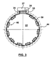
- a gas distribution manifold 50 is mounted to and extends at least substantially around a portion of the vertically extending inside wall 44 of the draft tube 22.
- the manifold 50 is mounted to inside wall 44 by welding of the manifold to the wall 44 whereby wall 44 and wall portions 45 of manifold 50 define the inside space or chamber of manifold 50.
- the wall portions 45 of the manifold are interconnected by spacers 47. Spacers 47 maintain the manifold wall portions 45 at spaced distance from the vertically extending inside wall 44 of the draft tube 22.
- an air exit manifold opening 43 is located at the upper most manifold wall portion 45.
- the manifold extends substantially around the draft tube 22 except for the position of the man hole cover 39.
- the man hole cover 39 permits access into the draft tube for repairs.
- the man hole cover is typically included at the end of a passageway or a corridor 37 located in the concrete foundation 34. Air may be supplied through the draft tube inside wall 44 at locations 35. This air then circulates in an annular fashion about the manifold 50 to escape out through the air exit manifold opening. It should be understood that the entrance 35 of air flow into the manifold 50 can be controlled by valves such that the air may be introduced into the manifold 50 during those months when the oxygen content of the water flowing through the draft tube 22 needs to be enhanced.
- a plurality of deflectors are shown for introducing oxygen containing gas into the water flowing through the draft tube.
- the oxygen containing gas preferably is air provided at ambient pressure.
- the plurality of the deflectors 46 are located in the draft tube closely adjacent to the blades 38 of the turbine. The closeness of these deflectors 46 to the turbine blades 38 permits for oxygen to be introduced at a relative lower water pressure as compared with the water pressure experienced further down the draft tube 22. Also, it is more beneficial to locate the deflector 46 adjacent the turbine blades 38 to enhance the mixing oxygen into the water flow.
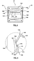
- each of the deflectors 46 has a flow control cover plate 134 overlying upstream and downstream plates 138, 140, respectively.
- the upstream plate 138 extends downwardly and outwardly relative from the vertically extending inside wall 44.
- an upper end portion of upstream plate 138 is welded to an upper manifold wall portion 45.
- the downstream plate 140 is welded at an upper end portion to the upstream plate 138.
- the downstream plate 140 extends downwardly and inwardly from the upstream plate 138.
- a lower edge portion of the down stream plate is welded to one of the manifold wall portions 45.
- the cover plate 134 is secured by spacers 136 welded to manifold wall portions 45 so as to provide a flow path for water through the deflector 46 of convergent-divergent cross-section, as seen in FIG. 2, and having a throat at the juncture 132 of plates 138, 140.
- the upstream plate 138, downstream plate 140 and side plates 142 are welded together and to one of the manifold wall portions 45. In this manner the deflector 46 is mounted relative from the inside wall 44 of the draft tube 22 via the wall portions 45 of the manifold 50. It should be understood that in other embodiments the whole or a part of the deflector 46 could be mounted either directly to the inner wall 44 of the draft tube 22 or some combination of the inner wall 44 and the manifold 50.
- the upstream plate 138 is referred to as upstream because it is upstream relative to plate 140 in the direction of water flowing through the draft tube 22 as shown by arrows 51 in FIGs. 1, 5 and 6. Further, the downstream plate 140 is referred to as downstream because it is positioned downstream of plate 138 in the direction 51 of water flowing through the draft tube 22.
- the upstream and downstream plates 138, 140 together with side plates 142 form an enclosure that overlays the air exit manifold opening 43 of the manifold 50. It should be understood that in an alternative embodiment, the air exit manifold opening 43 could simply be an air passageway extending through the inner wall 44 of draft tube 22. In this alternative embodiment, no manifold 50 would be employed.
- the upstream plate 138 is spaced from the cover plate 134 in converging relation therewith relative to the direction of water flow 51 through the deflector 46.
- the downstream plate 140 is spaced from the cover plate 134 in diverging relation therewith relative to the direction of water flow 51 through the deflector 46. This converging-diverging relationship creates a venturi or suction like effect immediately downstream of the juncture 132 between plates 138, 140.
- the cover plate 134 extends over the upstream and downstream plates 138, 140 and may, if desired, extend over a surface area beyond that of the upstream and downstream plates 138, 140.
- cover plate 134 may not be required and the abrupt corner at the juncture 132 between the upstream and downstream plates 138, 140 is sufficient in itself to create a negative pressure zone immediately downstream of the juncture 132.
- the upstream plate 138 has a back surface portion 160 and a first elongated lip portion 162 that extends laterally across the deflector 46.
- the downstream plate 140 extends from the back surface portion 160 of the upstream plate with the first elongated lip 162 overhanging the downstream plate 140.
- An elongated air communication port 170 is located in the downstream plate 140 that extends adjacent the upstream plate 138.
- the downstream plate 140 has a flat outer surface portion 166 and the air communication port 170 has a second elongated lip 172 that extends laterally across the downstream plate so as to define the elongated air communication port 170 between the first and second elongated lips 162, 172. As best seen in FIG.
- the first elongated lip 166 is rounded on a first end surface portion 167 facing into the elongated air communication port 170 and the second elongated lip 172 is rounded on a second end surface portion 173 facing out of the elongated air communication port 170 to thereby define angulation for the elongated air communication port 170 that is beneficial to the introduction of oxygen containing gas into water flowing past port 170.
- each of the deflectors 46 has an air supply inlet portion 200 that is positioned vertically above the elongated air communication port 170.
- the air supply inlet portion is positioned at the draft tube 22 in air flow communication with air exit manifold opening 43.
- the air supply inlet portion permits oxygen containing gas and preferably ambient air to enter the deflector 46 and to flow downwardly through the deflector 46 out the elongated air communication port 170 and into the water flowing past the downstream plate 140.
- the air exit manifold opening 43 is shown to be positioned vertically below the air communication port 170.
- the deflector 46 further includes baffle 210.
- Baffle 210 comprises the bottom wall for the deflector 46 which is welded to the end portion of the downstream plate 140.
- the baffle 210 extends upwardly relative to the wall portion 45 of the manifold 50 and extends to an inwardly turned baffle portion 220.
- Baffle portion 220 extends inwardly relative from the inner wall 44 of the draft tube 22 below the air supply inlet portion 200 and above the elongated air communication port 170.
- the baffle portion 220 in cross-section has an inside concave like wall 222 and an outside convex like wall 224. The curvature of the baffle portion 220 is believed to assist the circulation of air around the convex like wall 224 between this air supply inlet portion 200 and the upstream plate 138 and downwardly out the air communication port 170.
- an internal air flow passageway 226 is formed between the upstream plate 138 and the baffle portion 220.
- the baffle portion 220 together with baffle 210 and the downstream plate 140 form a water circulation chamber 250.
- Water circulation chamber 250 is positioned below the baffle portion 220 and behind the downstream plate 140.
- the concave curved wall 222 of the baffle portion 220 assists in the deflection of water passing through the elongated air communication port 170 into and out from the water circulation chamber 250.
- the air exit manifold opening 43 is positioned below the vertical upwardly extension of the baffle 210 and the baffle portion 220.
- the shape of the baffle portion 220 may be a straight shape that extends upwardly and outwardly at an angle of about 45 degrees, for example.
- the circulation of water within water chamber 250 is assisted by baffle portion 220.
- the vertical extension of baffle 210 effectively raises the position of the air supply inlet portion to be above the air communication port 170.
- the vertical extension provided by baffle 220 is not necessary in instances where the manifold has an air exit opening positioned above the air communication port 170. In any event, the air supply inlet portion 200 is to be positioned above the air communication port in order to benefit from the effects of gravity.
Landscapes
- Chemical & Material Sciences (AREA)
- Engineering & Computer Science (AREA)
- Chemical Kinetics & Catalysis (AREA)
- Combustion & Propulsion (AREA)
- Mechanical Engineering (AREA)
- General Engineering & Computer Science (AREA)
- Hydraulic Turbines (AREA)
Applications Claiming Priority (2)
| Application Number | Priority Date | Filing Date | Title |
|---|---|---|---|
| US834906 | 2004-04-30 | ||
| US10/834,906 US7044452B2 (en) | 2004-04-30 | 2004-04-30 | Hydraulic turbine draft tube deflector with enhanced dissolved oxygen |
Publications (2)
| Publication Number | Publication Date |
|---|---|
| EP1593843A2 true EP1593843A2 (de) | 2005-11-09 |
| EP1593843A3 EP1593843A3 (de) | 2012-07-04 |
Family
ID=34941102
Family Applications (1)
| Application Number | Title | Priority Date | Filing Date |
|---|---|---|---|
| EP20050252679 Ceased EP1593843A3 (de) | 2004-04-30 | 2005-04-28 | Ablenkungsplatte zum Sauerstofflösen in einem Saugrohr einer hydraulischen Turbine |
Country Status (3)
| Country | Link |
|---|---|
| US (1) | US7044452B2 (de) |
| EP (1) | EP1593843A3 (de) |
| CA (1) | CA2504172C (de) |
Families Citing this family (5)
| Publication number | Priority date | Publication date | Assignee | Title |
|---|---|---|---|---|
| NO325031B1 (no) * | 2006-07-04 | 2008-01-21 | Ge Energy Norway As | Vannturbin |
| US8314507B2 (en) | 2010-04-21 | 2012-11-20 | Kiser Hydro, Llc | Hydro unit retrofit and method of performing same |
| PT2873851T (pt) * | 2013-11-14 | 2016-10-25 | Alstom Renewable Technologies | Sistema de ventilação para turbina hidráulica |
| CN110848070A (zh) * | 2019-10-23 | 2020-02-28 | 江苏大学 | 一种水轮机曝气系统 |
| US11648517B2 (en) * | 2021-06-07 | 2023-05-16 | Andritz Hydro Canada Inc. | Aeration cone for hydraulic turbine |
Family Cites Families (26)
| Publication number | Priority date | Publication date | Assignee | Title |
|---|---|---|---|---|
| US2685429A (en) * | 1950-01-31 | 1954-08-03 | Gen Electric | Dynamic sealing arrangement for turbomachines |
| US3572658A (en) * | 1968-01-15 | 1971-03-30 | Richards Of Rockford Inc | Floating aerator |
| US3671022A (en) * | 1969-10-06 | 1972-06-20 | Air Reduction | Method and apparatus for the microdispersion of oxygen in water |
| CA901428A (en) | 1970-07-29 | 1972-05-30 | Dominion Engineering Works Limited | Hydraulic machine crown aeration |
| US4051204A (en) * | 1973-12-21 | 1977-09-27 | Hans Muller | Apparatus for mixing a liquid phase and a gaseous phase |
| CA1058055A (en) | 1976-11-26 | 1979-07-10 | Dominion Engineering Works Limited | Draft tube aeration with eductor |
| CA1062122A (en) | 1976-11-26 | 1979-09-11 | Dominion Engineering Works Limited | Draft tube aeration with check valves |
| CA1052662A (en) | 1976-11-26 | 1979-04-17 | Dominion Engineering Works Limited | Draft tube venting arrangement |
| US4512936A (en) * | 1981-07-03 | 1985-04-23 | Ebara Corporation | Aeration apparatus |
| US4515524A (en) * | 1982-09-27 | 1985-05-07 | Allis-Chalmers Corporation | Draft tube for hydraulic turbine |
| US4514343A (en) * | 1982-09-29 | 1985-04-30 | Air-O-Lator Corporation | Aspirating horizontal mixer |
| US4431597A (en) * | 1982-09-29 | 1984-02-14 | Air-O-Lator Corporation | Horizontal mixing aerator |
| SU1263902A1 (ru) | 1984-09-26 | 1986-10-15 | Производственное Объединение Турбостроения "Ленинградский Металлический Завод" | Устройство дл аэрации потока в проточном тракте гидротурбины |
| US4780051A (en) | 1985-05-23 | 1988-10-25 | Voith Hydro, Inc. | Hydraulic turbine aeration apparatus |
| GB9305010D0 (en) * | 1993-03-11 | 1993-04-28 | Rolls Royce Plc | A cooled turbine nozzle assembly and a method of calculating the diameters of cooling holes for use in such an assembly |
| GB9305012D0 (en) * | 1993-03-11 | 1993-04-28 | Rolls Royce Plc | Sealing structures for gas turbine engines |
| US5924842A (en) | 1996-10-17 | 1999-07-20 | Voith Hydro, Inc. | Hydraulic turbine for enhancing the level of dissolved gas in water |
| US5823740A (en) | 1997-02-25 | 1998-10-20 | Voith Hydro, Inc. | Dissolved gas augmentation with mixing chambers |
| US5941682A (en) | 1997-07-24 | 1999-08-24 | Voith Hydro, Inc. | Draft tube peripheral plenum |
| US6394423B1 (en) * | 1997-11-19 | 2002-05-28 | Thomas Joseph Vento | Multi-stage aerator |
| JPH11153081A (ja) * | 1997-11-21 | 1999-06-08 | Toshiba Corp | 給気構造を有する水力機械 |
| US6155783A (en) | 1998-05-20 | 2000-12-05 | Voith Siemens Hydro Power Generation, Inc. | Hollow blade for hydraulic turbine or pump |
| FR2809139B1 (fr) | 2000-05-16 | 2002-08-30 | Jacques Fonkenell | Installation hydraulique pouvant fonctionner en installation hydroelectrique ou en aerateur d'eau |
| JP2003184726A (ja) * | 2003-01-06 | 2003-07-03 | Toshiba Corp | 水力機械 |
| US6971843B2 (en) * | 2003-06-25 | 2005-12-06 | General Electric Canada Inc. | Hydraulic turbine draft tube with enhanced dissolved oxygen |
| US6854958B2 (en) * | 2003-07-09 | 2005-02-15 | General Electric Canada Inc. | Hydraulic turbine with enhanced dissolved oxygen |
-
2004
- 2004-04-30 US US10/834,906 patent/US7044452B2/en not_active Expired - Lifetime
-
2005
- 2005-04-14 CA CA 2504172 patent/CA2504172C/en not_active Expired - Fee Related
- 2005-04-28 EP EP20050252679 patent/EP1593843A3/de not_active Ceased
Also Published As
| Publication number | Publication date |
|---|---|
| US7044452B2 (en) | 2006-05-16 |
| EP1593843A3 (de) | 2012-07-04 |
| CA2504172C (en) | 2012-09-18 |
| CA2504172A1 (en) | 2005-10-30 |
| US20050242451A1 (en) | 2005-11-03 |
Similar Documents
| Publication | Publication Date | Title |
|---|---|---|
| US6971843B2 (en) | Hydraulic turbine draft tube with enhanced dissolved oxygen | |
| US5823740A (en) | Dissolved gas augmentation with mixing chambers | |
| JP5449060B2 (ja) | 風力発電装置 | |
| US6227819B1 (en) | Fuel pumping assembly | |
| EP0112829B1 (de) | Anordnung für radiale lüfter | |
| ES2931325T3 (es) | Turbina hidráulica | |
| CA2504172C (en) | Hydraulic turbine draft tube defector with enhanced dissolved oxygen | |
| JPH0262709B2 (de) | ||
| US20040253097A1 (en) | Hydropowered turbine system | |
| JP4249903B2 (ja) | 蒸気タービン | |
| US5941682A (en) | Draft tube peripheral plenum | |
| JP2020159285A (ja) | 吸込カバー、横軸ポンプ、ポンプゲートおよびポンプゲートの運転方法 | |
| CA1058055A (en) | Draft tube aeration with eductor | |
| US6854958B2 (en) | Hydraulic turbine with enhanced dissolved oxygen | |
| US4146351A (en) | Draft tube venting arrangement | |
| US7736128B2 (en) | Stress relief grooves for Francis turbine runner blades | |
| US1950777A (en) | Hydraulic turbine | |
| CN210343778U (zh) | 一种房车空调用的混流风机 | |
| CN115628172A (zh) | 一种减小轴流定桨水轮机尾水管涡带的环形补气装置 | |
| US3350059A (en) | Anti-circulation seal | |
| JP2004044409A (ja) | 水車用ランナ及び水車 | |
| JP3497574B2 (ja) | 水力機械 | |
| CN218324978U (zh) | 一种汽轮机蒸汽室 | |
| JP4876797B2 (ja) | 水力機械及び水力機械用ステーリング | |
| CN211422994U (zh) | 一种切割式导引排污泵的泵中段结构 |
Legal Events
| Date | Code | Title | Description |
|---|---|---|---|
| PUAI | Public reference made under article 153(3) epc to a published international application that has entered the european phase |
Free format text: ORIGINAL CODE: 0009012 |
|
| AK | Designated contracting states |
Kind code of ref document: A2 Designated state(s): AT BE BG CH CY CZ DE DK EE ES FI FR GB GR HU IE IS IT LI LT LU MC NL PL PT RO SE SI SK TR |
|
| AX | Request for extension of the european patent |
Extension state: AL BA HR LV MK YU |
|
| RIN1 | Information on inventor provided before grant (corrected) |
Inventor name: DESY, NORMAND Inventor name: DEMERS, ERIC |
|
| PUAL | Search report despatched |
Free format text: ORIGINAL CODE: 0009013 |
|
| AK | Designated contracting states |
Kind code of ref document: A3 Designated state(s): AT BE BG CH CY CZ DE DK EE ES FI FR GB GR HU IE IS IT LI LT LU MC NL PL PT RO SE SI SK TR |
|
| AX | Request for extension of the european patent |
Extension state: AL BA HR LV MK YU |
|
| RIC1 | Information provided on ipc code assigned before grant |
Ipc: F03B 11/00 20060101AFI20120531BHEP Ipc: F03B 3/12 20060101ALI20120531BHEP |
|
| AKY | No designation fees paid | ||
| REG | Reference to a national code |
Ref country code: DE Ref legal event code: R108 |
|
| REG | Reference to a national code |
Ref country code: DE Ref legal event code: R108 Effective date: 20130313 |
|
| STAA | Information on the status of an ep patent application or granted ep patent |
Free format text: STATUS: THE APPLICATION HAS BEEN REFUSED |
|
| 18R | Application refused |
Effective date: 20130405 |