EP1593859B1 - Élément de fixation pour le raccordement libérables et anti-vibrant d'un premier élément avec un deuxième élément - Google Patents
Élément de fixation pour le raccordement libérables et anti-vibrant d'un premier élément avec un deuxième élément Download PDFInfo
- Publication number
- EP1593859B1 EP1593859B1 EP05008593A EP05008593A EP1593859B1 EP 1593859 B1 EP1593859 B1 EP 1593859B1 EP 05008593 A EP05008593 A EP 05008593A EP 05008593 A EP05008593 A EP 05008593A EP 1593859 B1 EP1593859 B1 EP 1593859B1
- Authority
- EP
- European Patent Office
- Prior art keywords
- connecting element
- insert
- spring
- inner sleeve
- spring element
- Prior art date
- Legal status (The legal status is an assumption and is not a legal conclusion. Google has not performed a legal analysis and makes no representation as to the accuracy of the status listed.)
- Expired - Lifetime
Links
- 238000013016 damping Methods 0.000 claims abstract description 22
- 239000004033 plastic Substances 0.000 claims description 12
- 239000000463 material Substances 0.000 claims description 11
- 230000001447 compensatory effect Effects 0.000 claims 3
- 238000004519 manufacturing process Methods 0.000 description 8
- 239000000872 buffer Substances 0.000 description 6
- 238000004026 adhesive bonding Methods 0.000 description 4
- 238000009434 installation Methods 0.000 description 4
- 239000007769 metal material Substances 0.000 description 4
- 239000013013 elastic material Substances 0.000 description 3
- 238000003860 storage Methods 0.000 description 3
- 238000005553 drilling Methods 0.000 description 2
- 238000004073 vulcanization Methods 0.000 description 2
- 229910000639 Spring steel Inorganic materials 0.000 description 1
- 230000005540 biological transmission Effects 0.000 description 1
- 230000015572 biosynthetic process Effects 0.000 description 1
- 238000007906 compression Methods 0.000 description 1
- 230000006835 compression Effects 0.000 description 1
- 238000011161 development Methods 0.000 description 1
- 230000018109 developmental process Effects 0.000 description 1
- 238000005304 joining Methods 0.000 description 1
- 238000000034 method Methods 0.000 description 1
- 229920001296 polysiloxane Polymers 0.000 description 1
- 238000003825 pressing Methods 0.000 description 1
- 238000004080 punching Methods 0.000 description 1
- 239000012858 resilient material Substances 0.000 description 1
- 238000003892 spreading Methods 0.000 description 1
- 238000003466 welding Methods 0.000 description 1
Images


Classifications
-
- F—MECHANICAL ENGINEERING; LIGHTING; HEATING; WEAPONS; BLASTING
- F16—ENGINEERING ELEMENTS AND UNITS; GENERAL MEASURES FOR PRODUCING AND MAINTAINING EFFECTIVE FUNCTIONING OF MACHINES OR INSTALLATIONS; THERMAL INSULATION IN GENERAL
- F16B—DEVICES FOR FASTENING OR SECURING CONSTRUCTIONAL ELEMENTS OR MACHINE PARTS TOGETHER, e.g. NAILS, BOLTS, CIRCLIPS, CLAMPS, CLIPS OR WEDGES; JOINTS OR JOINTING
- F16B5/00—Joining sheets or plates, e.g. panels, to one another or to strips or bars parallel to them
- F16B5/02—Joining sheets or plates, e.g. panels, to one another or to strips or bars parallel to them by means of fastening members using screw-thread
- F16B5/0241—Joining sheets or plates, e.g. panels, to one another or to strips or bars parallel to them by means of fastening members using screw-thread with the possibility for the connection to absorb deformation, e.g. thermal or vibrational
-
- F—MECHANICAL ENGINEERING; LIGHTING; HEATING; WEAPONS; BLASTING
- F16—ENGINEERING ELEMENTS AND UNITS; GENERAL MEASURES FOR PRODUCING AND MAINTAINING EFFECTIVE FUNCTIONING OF MACHINES OR INSTALLATIONS; THERMAL INSULATION IN GENERAL
- F16B—DEVICES FOR FASTENING OR SECURING CONSTRUCTIONAL ELEMENTS OR MACHINE PARTS TOGETHER, e.g. NAILS, BOLTS, CIRCLIPS, CLAMPS, CLIPS OR WEDGES; JOINTS OR JOINTING
- F16B5/00—Joining sheets or plates, e.g. panels, to one another or to strips or bars parallel to them
- F16B5/02—Joining sheets or plates, e.g. panels, to one another or to strips or bars parallel to them by means of fastening members using screw-thread
- F16B5/025—Joining sheets or plates, e.g. panels, to one another or to strips or bars parallel to them by means of fastening members using screw-thread specially designed to compensate for misalignement or to eliminate unwanted play
-
- Y—GENERAL TAGGING OF NEW TECHNOLOGICAL DEVELOPMENTS; GENERAL TAGGING OF CROSS-SECTIONAL TECHNOLOGIES SPANNING OVER SEVERAL SECTIONS OF THE IPC; TECHNICAL SUBJECTS COVERED BY FORMER USPC CROSS-REFERENCE ART COLLECTIONS [XRACs] AND DIGESTS
- Y10—TECHNICAL SUBJECTS COVERED BY FORMER USPC
- Y10S—TECHNICAL SUBJECTS COVERED BY FORMER USPC CROSS-REFERENCE ART COLLECTIONS [XRACs] AND DIGESTS
- Y10S403/00—Joints and connections
- Y10S403/14—Resilient cinch, locking-catch or retainer type
-
- Y—GENERAL TAGGING OF NEW TECHNOLOGICAL DEVELOPMENTS; GENERAL TAGGING OF CROSS-SECTIONAL TECHNOLOGIES SPANNING OVER SEVERAL SECTIONS OF THE IPC; TECHNICAL SUBJECTS COVERED BY FORMER USPC CROSS-REFERENCE ART COLLECTIONS [XRACs] AND DIGESTS
- Y10—TECHNICAL SUBJECTS COVERED BY FORMER USPC
- Y10T—TECHNICAL SUBJECTS COVERED BY FORMER US CLASSIFICATION
- Y10T24/00—Buckles, buttons, clasps, etc.
- Y10T24/30—Trim molding fastener
- Y10T24/304—Resilient metal type
-
- Y—GENERAL TAGGING OF NEW TECHNOLOGICAL DEVELOPMENTS; GENERAL TAGGING OF CROSS-SECTIONAL TECHNOLOGIES SPANNING OVER SEVERAL SECTIONS OF THE IPC; TECHNICAL SUBJECTS COVERED BY FORMER USPC CROSS-REFERENCE ART COLLECTIONS [XRACs] AND DIGESTS
- Y10—TECHNICAL SUBJECTS COVERED BY FORMER USPC
- Y10T—TECHNICAL SUBJECTS COVERED BY FORMER US CLASSIFICATION
- Y10T403/00—Joints and connections
- Y10T403/60—Biased catch or latch
- Y10T403/606—Leaf spring
Definitions
- the invention relates to a connecting element for detachable and vibration-damping connection of a first component with a second component and the possibility of tolerance compensation between the first and the second component in a balancing direction with a damping ring attachable in the first component and with an inner sleeve and a spring element with a spring element elongated hole, wherein a retaining bolt between two spring surfaces of the spring element can be latched substantially parallel to a latching direction.
- Detachable fasteners for joining components are widely used in the art. They are used for example in automotive or aircraft to connect interior trim parts with external support structures of the body or the fuselage cell.
- From the DE 200 16 889 U1 is an adjustable in two directions plate unit for releasable spring clips for attachment of wall paneling elements or the like.
- the from the DE 200 16 889 U1 Prior art connecting elements each have a spring element, in which either a slot or a cylindrical bore is introduced. Through the slot tolerance compensation between the components to be joined is possible, whereas no tolerance compensation is possible with the cylindrical bore.
- a vibration damper ring insert assembly is known.
- the insert assembly comprises in a variant a substantially hollow cylindrical sleeve, which is surrounded by an elastic vibration damper ring and fixedly connected thereto.
- the vibration damper ring is in turn surrounded by a hollow cylinder which is accommodated by means of a securing ring in a component bore in a first component.
- a lower base part has a retaining spring arrangement with four retaining spring arms.
- the DE 100 57 947 A1 relates to a connection arrangement for releasably connecting a first component to a second component with a sleeve-guided bolt which is fixedly connected to an annular unlocking.
- a vibration damper ring made of an elastic material can be used by means of a circumferential groove in a mounting hole in the second component.
- the vibration damper ring has an approximately hollow cylindrical designed clamping bracket, the lower end is flanged.
- the first component also has a mounting hole in which a substantially hollow cylindrical sleeve is arranged. The attachment of the sleeve is done with a locking ring. In the sleeve, an axially displaceable bolt is resiliently received.
- connection of the two components is effected by an introduced in the lower portion of the bolt annular recess into which engage the engagement portions of leaf spring arms.
- the object of the invention is to reduce in particular the production cost of the connecting elements by simplifying the manufacturing process.
- connection element characterized in that the inner sleeve has an insert and the spring element is connected to a locking plate and an upper collar of the inner sleeve between a base plate of the spring element and the locking plate is arranged,
- the connection element according to the invention can be formed in a simple manner by varying only a simple component in the form of inserts to be introduced into the inner sleeve, both for connections without tolerance compensation and for connections with tolerance compensation. According to the invention, it is only necessary to introduce a slot in the spring element.
- the possibility of tolerance compensation by means of the connecting element is inventively created simply by different variants of the insert in the inner sleeve, wherein the insert has a cylindrical bore in a variant and a slot in a second variant.
- An advantageous embodiment of the invention provides that in the insert a hole is made to enable a connection without tolerance compensation.
- a connecting element can be formed in a simple manner by the use of an insert with a particular cylindrical bore for the connection of components without the possibility of tolerance compensation. It is no longer necessary to introduce a cylindrical bore in the spring element instead of the elongated hole.
- a slot is provided in the insert for enabling a connection with tolerance compensation.
- the connecting element can be designed according to a simple manner for a connection of components with the possibility of tolerance compensation.
- the insert is formed with a plastic material.
- This embodiment enables a particularly simple production of the connecting element, since plastic materials can be processed more easily than metallic materials.
- inserts made with a plastic material can be easily fastened in the inner sleeve of the connecting element, for example by gluing, pressing in, pinching or the like.
- the insert is firmly connected to the inner sleeve, in particular glued into this, vulcanized, pressed or clamped. If the insert is fastened to the inner sleeve essentially in a non-detachable manner, in particular by press-fitting or clamping, then the connecting element can be easily inserted directly before the application by a user by inserting an insert with a bore or an insert with a slot either for connections without tolerance compensation or be designed for connections with tolerance compensation.
- the insert may comprise suitable connection means for substantially non-detachable connection with the inner sleeve.
- Fig. 1 shows a schematic side view of the connecting element according to the invention.
- identical structural elements each have the same reference numerals.
- a connecting element 1 comprises inter alia a spring element 2, a locking plate 3 and a damping ring 4 for vibration damping or decoupling of the components to be connected.
- an inner sleeve 5 is arranged within the damping ring 4, an inner sleeve 5 is arranged.
- the spring element 2 has a first and a second spring surface 6, 7.
- the spring element 2 is formed from a resilient material, such as spring steel, suitable plastic materials or the like.
- the first spring surface 6 has a first latching lug 8.
- the second spring surface 7 is provided with a second latching lug 9.
- the first and the second locking lug 8.9 serve in a corresponding to the locking lugs 8.9 formed on both sides of a recess in the representation of Fig. 1 not shown holding bolt releasably engage.
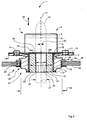
- the Fig. 2 shows a detailed section through the connecting element 1 according to the invention without the possibility of tolerance compensation.
- the spring element 2 includes the first spring surface 6 and in the representation of Fig. 2 invisible second spring surface 7, which is arranged behind the first spring surface 6. From the spring element 2 outgoing forces are transmitted from the inner sleeve 5 and the backup plate 3 on the damping ring 4.
- the spring element 2 is fixed on the locking plate 3 by the rivets 10,11. Alternatively, an attachment by spot welding, bonding, etc. is possible.
- a retaining pin 12 with a vertical axis 13 - indicated by a dashed outline - releasably engaged in case of need by means of an actuating element, not shown.
- the engagement of the retaining pin 12 between the spring surfaces 6,7 takes place here parallel to a locking direction 14.
- Die Fig. 2 shows the retaining pin 12 in the locked state.
- the retaining pin 12 is in the locked state, a non-positive connection of the connecting element 1 to a in the Fig. 2 the sake of clarity not shown second component ago.
- the retaining bolt 12 can engage between the spring surfaces 6, 7, the retaining bolt 12 has recesses formed on both sides in the end region corresponding to the latching lugs 8, 9 into which the latching lugs 8, 9 can be introduced in a form-fitting manner at least in regions.
- the depressions are in the representation of Fig. 2 for the sake of clarity also not shown.
- an upper collar 16 of the inner sleeve 5 is mechanically clamped or clamped.
- the firm clamping of the upper collar 16 results from the fact that the spring element 2 firmly connected to the backup plate 3, in particular riveted, welded, pressed, clamped or otherwise secured.
- the inner sleeve 5 is preferably surrounded on all sides by the damping ring 4.
- the damping ring 4 is formed with a vibration damping material, such as rubber, silicone, plastic or the like.
- the damping ring 4 is also firmly connected to the inner sleeve 5, in particular glued to this, vulcanized, pressed, clamped or otherwise secured.
- the inner sleeve 5 is preferably formed with a metallic material, but may alternatively be made with a plastic material.
- the inner sleeve 5 also has a lower collar 17 for safe two-sided enclosure of the damping ring 4.
- a spring element long hole 18 for the implementation of the retaining bolt 12 is introduced.
- the spring element long hole 18 in this case has a length 19, which ensures a sufficient displaceability of the retaining bolt 12 between the spring surfaces 6,7 in a compensation direction 20, if the possibility of a tolerance compensation is desired.
- One in the Fig. 2 not representable and therefore not provided with a reference numeral width of the spring element elongated hole 18 which extends perpendicular to the plane, is preferably chosen so that the width of the spring element elongated hole 18 corresponds approximately to an outer diameter 21 of the retaining bolt 12 to avoid jamming.
- an insert 22 according to the invention is preferably arranged insoluble.
- the insert 22 can be glued into the inner sleeve 5, vulcanized, pressed, clamped or otherwise secured in this.
- the insert 22 is preferably formed with a plastic material.
- the insert 22 has in the representation of Fig. 2 a bore 23, whose bore diameter 24 substantially corresponds to the outer diameter 21 of the retaining bolt 12, so that the retaining bolt 12 can be performed preferably without or with only a slight mechanical play through the insert 22 for connecting the components.
- the wall thickness of the insert 22 corresponds approximately to an inner sleeve diameter 25 less the bore diameter 24.
- the points in the Fig. 2 shown embodiment variant of the connecting element 1 is not the possibility of tolerance compensation in the compensation direction 20, because the retaining pin 12 is received virtually without mechanical play in the insert 22 and thus only parallel to the vertical axis 13 is displaceable.
- the connecting element 1 have the possibility of tolerance compensation in the compensation direction 20, then only the bore 23 is formed in the insert 22 as a slot, or it is a similar use with a slot inserted into the inner sleeve 5. All other components of the connecting element 1 remain structurally unchanged.
- the connecting element 1 can be equipped with the possibility of a tolerance compensation or without the possibility of tolerance compensation either already during manufacture or only immediately before installation by the alternative use of an insert with a slot or an insert with a cylindrical bore.
- the insert 22 may for this purpose on its outer surface, for example, projections which can be pressed into corresponding recesses of an inner surface of the inner sleeve 5 in order to create a substantially non-detachable connection of the insert 22 with the inner sleeve 5.
- the fixed connection of the insert 22 with the inner sleeve 5 can also be done by other connection techniques, for example by latching, screwing, gluing or the like.
- a user can immediately before the installation of the connecting element 1 according to the invention by inserting the corresponding insert 22 with a cylindrical bore or with a slot form the connecting element 1 for connection tasks without the need for tolerance compensation or with the requirement of tolerance compensation.
- complete, complete fasteners can be made, which are already provided with inserts for connection tasks without the need for a tolerance compensation as well as for those with the need for tolerance compensation, which, however, the storage costs increased slightly.
- the inserts 22 in this case in a known manner, for example by gluing, vulcanization or the like, are permanently attached in the inner sleeves.
- the insert 22 according to the invention also reduces noise developments or largely prevents the formation of rattling noises caused by movements of the retaining bolt 12 within the inner sleeve 5 and in the spring element 2 may arise when no insert 22 is present in the inner sleeve 5.
- a circumferential recess 26 and a recess is introduced, which essentially serves for fastening of the connecting element 1 in the component.
- an outer sleeve 27 is arranged, wherein the outer sleeve 27 is fixedly connected to the recess 26, for example by gluing, vulcanization, compression, jamming or the like.
- the outer sleeve 27 is also formed with a metallic material, but may alternatively be made with a plastic material.
- the outer sleeve 27 has a circumferential retaining collar 28.
- the retaining collar 28 serves to provide a contact surface 29, by means of which forces are transmitted from the connecting element 1 to a first component 30.
- a mounting hole 31 is introduced with a mounting hole diameter 32 for fixing the connecting element 1.
- the outer sleeve 27 is disposed or inserted within the mounting hole 31.
- a circumferential securing ring 33 By means of a circumferential securing ring 33, the outer sleeve 27 and thus the entire connecting element 1 is secured within the mounting hole 31 of the first component 30.
- the securing ring 33 can no longer readily be removed from the outer sleeve 27 after its application to the outer sleeve 27, because it jams with the outer sleeve 27.
- the connecting element 1 is secured in an insoluble manner in an edge region 34 of the mounting hole 31 and firmly connected to the first component 30.
- An outer diameter 35 of the locking plate 3 is preferably selected so that the connecting element 1 is not pulled through the mounting hole 31 in case of any failure, that is, for example, in a break or rupture of the damping ring 4.
- the advantage of the connecting element 1 according to the invention lies in particular in that only the insert 22 by the alternative introduction of a cylindrical bore or an elongated hole must be varied in order to provide a connecting element 1 without or with tolerance compensation possibility, while the remaining components can remain unchanged. Since the insert 22 is preferably formed with a plastic material, both the cylindrical bore 23 and, alternatively, a slot can very easily bring in this, whereby the manufacturing cost is considerably reduced.
- the Fig. 3 shows the connecting element 1 according to the invention with the possibility of tolerance compensation by another use in a plan view, wherein the spring surfaces are broken away 6.7 for the sake of clarity.
- the rivets 10,11 connect the locking plate 3 with the spring element. 2
- the spring element 2 has the spring element long hole 18 with the length 19 and a width 36.
- another insert 37 is used, in which, in contrast to the insert 22 in accordance with the Fig. 2 a slot 38 is introduced. Only for comparison purposes, the spatial extent of the insert 22 with the bore 23 is shown in dashed lines (see. Fig. 2 ).
- the slot 38 has a smaller length 39 than the length 19 of the spring element elongated hole 18 because of the better graphic representability.
- a width 40 of the slot 38 in the insert 37 corresponds in the embodiment shown approximately to the width 36 of the spring element elongated hole 18th
- the spring element long hole 18 and the slot 38 in the insert 37 are formed substantially congruent, the length 19 of the spring element long hole 18 and the length 39 of the slot 38 are selected so that the insert 37 is still a sufficient minimum Wall thickness has.
- the minimum wall thickness of the insert 37 results here from the difference between the inner sleeve diameter 25 and the length 39 of the slot 38 in the insert 37.
- the minimum wall thickness of the insert 37 should preferably not fall below a value of approximately 0.3 mm in order to have sufficient mechanical strength To ensure stability of the insert 37.
- Corresponding considerations also apply to a minimum wall thickness of the embodiment with an insert 22 having a cylindrical bore 23.
- the length 19 of the spring element long hole 18 and the length 39 of the slot 38 in the insert 37 are also dimensioned so that sufficient for all load and operating conditions of the connecting element 1 tolerance compensation between the components to be connected in the balancing direction 20 is possible.
- the width 36 of the spring element long hole 18 and the width 40 of the slot 38 in the insert 37 are hereby preferably chosen so that the retaining pin 12 performed during assembly with a slight mechanical play through the spring element long hole 18 and the slot 38 in the insert 37 without the risk of jamming can be.
- both the spring element long hole 18 and the slot 38 in the insert 37 each have a different length 19,39 and / or a different width 36,40.
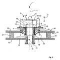
- the Fig. 4 shows a section through a mounted connecting element 1 with tolerance compensation between the components.
- the connecting element 1 is, as in the description of the Fig. 2 has already been explained in detail, among other things by the damping ring 4 mounted within the first member 30.
- the spring element 2 in turn has the spring element long hole 18.
- the base plate 15 of the spring element 2 is connected by means of the rivets 10,11 with the backup plate 3.
- the retaining bolt 12 has on both sides, arranged on opposite sides recesses 41,42 into which the detents 8,9 of the spring element 2 engage on both sides in the direction of the locking direction 14 and at least partially rest positively.
- the retaining bolt 12 is pivotable about the vertical axis 13 and thus in case of need from the spring element 2 by spreading the spring surfaces 6,7 again disengaged.
- the retaining bolt 12 has at the lower end to a head portion 44 which is supported on a second component 45 and is received in this pivotally and serves for the power transmission.
- a Bore 46 introduced with a diameter that allows easy pivoting of the retaining pin 12.
- the inner sleeve 5 is in correspondence to the representation of Fig. 3 arranged the use 37, in which the slot 38 is introduced.
- the structural design of the in the context of Fig. 2 Due to the oblong hole 38 in the insert 37, the first and the second component 30, 45 are displaceable relative to one another in the compensation direction 20. If no tolerance compensation in the compensation direction 20 is desired, then instead of the insert 37, the insert 22 (cf. Fig. 2 ) is inserted into the inner sleeve 5, which has the cylindrical bore 23.
- At least two bumpers 47, 48 are arranged between the first component 30 and the second component 45 in order to ensure a defined pretension between the components 30, 45 and thus to prevent any possible rattling noise as a result of relative movements between the components 30, 45.
- a centric, the retaining pin 12 at least partially enclosing buffers may be provided.
- the buffers 47, 48 or the centric buffer are preferably formed with an elastic material, for example plastic, rubber, rubber or the like.
- the retaining bolt 12 is formed with a metallic material, a plastic material or the like.
- the connecting element according to the invention is in particular intended to plate elements for interior linings of means of transport, in particular of Aircraft, if necessary, easily detachable with a substructure, which serves to attach the inner lining to the fuselage cell structure to connect.
Landscapes
- Engineering & Computer Science (AREA)
- General Engineering & Computer Science (AREA)
- Mechanical Engineering (AREA)
- Vibration Prevention Devices (AREA)
- Springs (AREA)
- Fixed Capacitors And Capacitor Manufacturing Machines (AREA)
- Snaps, Bayonet Connections, Set Pins, And Snap Rings (AREA)
Claims (13)
- Elément d'assemblage (1) pour l'assemblage amovible et amortisseur de vibrations d'un premier composant (30) avec un second composant (45) et pour permettre une compensation de tolérances entre le premier et le second composant (30, 45) dans une direction d'équilibrage (20), comprenant un anneau amortisseur (4) qui peut être fixé dans le premier composant (30), un manchon intérieur (5) et un élément à ressort (2) avec un trou oblong (18), un axe de retenue (12) pouvant être encliqueté entre deux surfaces de ressort (6, 7) de l'élément à ressort (2) de façon essentiellement parallèle à une direction d'encliquetage (14), caractérisé en ce que le manchon intérieur (5) présente un insert (22, 37), l'élément à ressort (2) est assemblé avec une plaque de blocage (3), et un collet supérieur (16) du manchon intérieur (5) est disposé entre une plaque de base (15) de l'élément à ressort (2) et la plaque de blocage (3).
- Elément d'assemblage (1) suivant la revendication 1, caractérisé en ce qu'un alésage (23) est pratiqué dans l'insert (22) pour permettre un assemblage sans compensation de tolérances.
- Elément d'assemblage (1) suivant la revendication 1, caractérisé en ce qu'un trou oblong (38) est pratiqué dans l'insert (37) pour permettre un assemblage avec compensation de tolérances.
- Elément d'assemblage (1) suivant l'une des revendications 1 à 3, caractérisé en ce que l'insert (22, 37) est formé d'une matière plastique.
- Elément d'assemblage (1) suivant l'une des revendications 1 à 4, caractérisé en ce que l'insert (22, 37) est assemblé fixement avec le manchon intérieur (5), est en particulier collé, vulcanisé, emmanché ou coincé dans ce dernier.
- Elément d'assemblage (1) suivant l'une des revendications 1 à 5, caractérisé en ce que l'anneau amortisseur (4) présente un creux périphérique (26) extérieur, dans lequel est disposé un manchon extérieur (27) muni d'un collet de retenue (28) pour créer une surface d'appui (29) pour l'élément d'assemblage (1) dans une zone de bordure (34) d'un trou de fixation (31) à l'intérieur du premier composant (30) et l'anneau amortisseur (4) peut être maintenu par un circlip (33) dans le trou de fixation (31).
- Elément d'assemblage (1) suivant l'une des revendications 1 à 6, caractérisé en ce que l'élément à ressort (2) est formé d'une première et d'une seconde surface de ressort (6, 7), qui sont disposées de façon essentiellement parallèle l'une par rapport à l'autre.
- Elément d'assemblage (1) suivant l'une des revendications 1 à 7, caractérisé en ce que le manchon intérieur (5) présente une géométrie de section transversale essentiellement circulaire, avec un diamètre de manchon intérieur (25).
- Elément d'assemblage (1) suivant l'une des revendications 1 à 8, caractérisé en ce qu'un diamètre extérieur (35) de la plaque de blocage (3) est plus grand qu'un diamètre (32) du trou de fixation.
- Elément d'assemblage (1) suivant l'une des revendications 1 à 9, caractérisé en ce que la première et la seconde surface de ressort (6, 7) présente chacune des premier et des second ergots d'encliquetage (8, 9) dirigés l'un vers l'autre, lesquels ergots peuvent être amenés par encliquetage dans des creux correspondants (41, 42) bilatéraux de l'axe de retenue (12).
- Elément d'assemblage (1) suivant l'une des revendications 1 à 10, caractérisé en ce que le manchon intérieur (5) est assemblé fixement avec l'anneau amortisseur (4), en particulier par collage, emmanchement, coinçage ou vulcanisation.
- Elément d'assemblage (1) suivant l'une des revendications 1 à 11, caractérisé en ce que le manchon extérieur (27) est assemblé fixement avec l'anneau amortisseur (4), en particulier par collage, compression, coinçage ou vulcanisation.
- Elément d'assemblage (1) suivant l'une des revendications 1 à 12, caractérisé en ce que l'élément à ressort (2) est assemblé fixement avec la plaque de blocage (3), en particulier riveté, soudé ou collé avec la plaque de blocage (3).
Applications Claiming Priority (2)
| Application Number | Priority Date | Filing Date | Title |
|---|---|---|---|
| DE102004022809 | 2004-05-08 | ||
| DE102004022809 | 2004-05-08 |
Publications (3)
| Publication Number | Publication Date |
|---|---|
| EP1593859A2 EP1593859A2 (fr) | 2005-11-09 |
| EP1593859A3 EP1593859A3 (fr) | 2006-01-25 |
| EP1593859B1 true EP1593859B1 (fr) | 2009-03-04 |
Family
ID=34935429
Family Applications (1)
| Application Number | Title | Priority Date | Filing Date |
|---|---|---|---|
| EP05008593A Expired - Lifetime EP1593859B1 (fr) | 2004-05-08 | 2005-04-20 | Élément de fixation pour le raccordement libérables et anti-vibrant d'un premier élément avec un deuxième élément |
Country Status (4)
| Country | Link |
|---|---|
| US (1) | US7445401B2 (fr) |
| EP (1) | EP1593859B1 (fr) |
| AT (1) | ATE424513T1 (fr) |
| DE (1) | DE502005006730D1 (fr) |
Families Citing this family (6)
| Publication number | Priority date | Publication date | Assignee | Title |
|---|---|---|---|---|
| DE102005030997B3 (de) | 2005-07-02 | 2006-12-28 | Airbus Deutschland Gmbh | Universalhalter, insbesondere zur Befestigung von Verkleidungselementen und/oder Zusatzeinrichtung in Luftfahrzeugen |
| US20070157544A1 (en) * | 2005-12-15 | 2007-07-12 | Benjamin Zurn | Novel muntin bar assemblies |
| EP3284616B1 (fr) * | 2016-08-16 | 2022-06-22 | Hill-Rom Services, Inc. | Ensemble d'actionneur et procédé d'assemblage |
| DE102016118640B4 (de) * | 2016-09-30 | 2024-10-17 | Witte Automotive Gmbh | Federelement |
| US11542976B2 (en) * | 2019-03-15 | 2023-01-03 | Magnesium Products of America Inc. | Tolerance compensator |
| DE102019206750B4 (de) * | 2019-05-09 | 2025-10-09 | Witte Automotive Gmbh | Vorrichtung zum Ausgleichen von Toleranzen zwischen einem ersten Bauteil und einem zweiten Bauteil |
Family Cites Families (10)
| Publication number | Priority date | Publication date | Assignee | Title |
|---|---|---|---|---|
| BE434446A (fr) * | 1938-01-14 | 1900-01-01 | ||
| US3292479A (en) * | 1964-11-19 | 1966-12-20 | George A Tinnerman | Snap socket fastener |
| DE29716096U1 (de) | 1997-09-08 | 1997-10-30 | Schwarz Verbindungs-Systeme GmbH, 75382 Althengstett | Schnellverschluß |
| DE29920497U1 (de) * | 1999-11-23 | 2000-02-17 | Schwarz Verbindungs-Systeme GmbH, 75382 Althengstett | Schwingungsdämpfende lösbare Verbindungsanordnung für zwei Bauteile mit einem Drehbolzen, einer Haltefeder und einem Schwingungsdämpferring |
| DE29920498U1 (de) * | 1999-11-23 | 2000-02-17 | Schwarz Verbindungs-Systeme GmbH, 75382 Althengstett | Verbindungsanordnung zum lösbaren Verbinden zweier Bauteile mit einem hülsengeführten Bolzen, der mit einem ringförmigen Entriegelungsteil fest verbunden ist |
| DE29920499U1 (de) | 1999-11-23 | 2000-02-17 | Schwarz Verbindungs-Systeme GmbH, 75382 Althengstett | Schwingungsdämpfende Verbindungsanordnung zum lösbaren Verbinden zweier Bauteile mit einem auf einem hülsengeführten Bolzen verschiebbaren Entriegelungsteil |
| DE20015848U1 (de) * | 2000-09-13 | 2000-12-28 | Schwarz Verbindungs-Systeme GmbH, 75382 Althengstett | Verbindungsanordnung zum lösbaren Verbinden zweier Bauteile mit einem Halte-Bolzen, einer Halte-Feder-Anordnung, einem Entriegelungs-Teil und einem Auslösestift |
| DE20016889U1 (de) | 2000-09-29 | 2000-12-21 | Schwarz Verbindungs-Systeme GmbH, 75382 Althengstett | In X/Y-Richtung justierbare Platten-Einheit für lösbar durch Feder-Clips anzubringende Wandverkleidungselemente o.dgl. |
| DE20218300U1 (de) * | 2002-11-26 | 2003-02-13 | Schwarz Verbindungssysteme GmbH, 75382 Althengstett | Lösbare Rast-/Schraub-Verbindungsanordnung |
| DE20218301U1 (de) | 2002-11-26 | 2003-02-13 | Schwarz Verbindungssysteme GmbH, 75382 Althengstett | Schwingungsdämpferring-Einsatzanordnung, auch in Verbindungsanordnungen für Bauteile |
-
2005
- 2005-04-20 DE DE502005006730T patent/DE502005006730D1/de not_active Expired - Lifetime
- 2005-04-20 AT AT05008593T patent/ATE424513T1/de not_active IP Right Cessation
- 2005-04-20 EP EP05008593A patent/EP1593859B1/fr not_active Expired - Lifetime
- 2005-05-06 US US11/123,988 patent/US7445401B2/en not_active Expired - Lifetime
Also Published As
| Publication number | Publication date |
|---|---|
| US20050254889A1 (en) | 2005-11-17 |
| EP1593859A2 (fr) | 2005-11-09 |
| DE502005006730D1 (de) | 2009-04-16 |
| US7445401B2 (en) | 2008-11-04 |
| EP1593859A3 (fr) | 2006-01-25 |
| ATE424513T1 (de) | 2009-03-15 |
Similar Documents
| Publication | Publication Date | Title |
|---|---|---|
| DE102007061926A1 (de) | Stecker, Halter und daraus gebildete Steckhalterung | |
| EP3606771B1 (fr) | Système de palier conçu pour supporter de manière élastique une jambe de force ou un amortisseur de vibrations, et jambe de force ou amortisseur de vibrations | |
| EP1744063A2 (fr) | Dispositif compensateur de tolérance en matière plastique | |
| EP2683591B1 (fr) | Volant pour véhicule automobile | |
| DE202008010262U1 (de) | Verbindungsbaugruppe zur Befestigung eines Anbauelements auf einem Trägerelement | |
| DE102013004515B4 (de) | Einrichtung zum lösbaren Befestigen eines Montageteils | |
| DE102019104386A1 (de) | Schwingungstilger | |
| DE102019113663B4 (de) | Abstandhalter für eine befestigungsanordnung, befestigungsanordnung mit einem solchen abstandhalter sowie verfahren zum befestigen eines montageteils an einem trägerteil | |
| WO2017032545A1 (fr) | Accouplement emboîtable en deux parties servant à l'assemblage de pièces | |
| DE102016109499A1 (de) | System aus einem Bauteil und einer Befestigungsvorrichtung | |
| EP3650290A1 (fr) | Module de sac gonflage, son procédé de montage ainsi que module de direction doté d'un tel module de sac gonflage | |
| DE102012221679B4 (de) | Toleranzausgleichsvorrichtung | |
| EP3803148B1 (fr) | Support antivibratoire en caoutchouc pour une unité motrice dans un véhicule | |
| EP1188936B1 (fr) | Assemblage de connection pour la fixation amovible de deux éléments | |
| WO2008046467A1 (fr) | Accouplement par emboîtement verrouillable | |
| DE102023207479A1 (de) | Vorrichtung zum Ausgleichen von Toleranzen | |
| EP4105497A1 (fr) | Dispositif de maintien et son procédé d'application | |
| DE10226092A1 (de) | Elastisches Kopplungsbauteil, Anordnung mit zwei im Betrieb Schwingungen und/oder Vibrationen ausgesetzten Bauteilen und Träger zum Halten eines Bauteils an einem im Betrieb Schwingungen und/oder Vibrationen ausgesetzen Bauteil | |
| DE102008062457B4 (de) | Befestigungsanordnung, Befestigungselement und Verfahren zur Befestigung dieser | |
| DE102012020569B4 (de) | Zusatzfeder, Dämpferlager und Stoßdämpfer | |
| EP1593859A2 (fr) | Élément de fixation pour le raccordement libérables et anti-vibrant d'un premier élément avec un deuxième élément | |
| DE102012010429A1 (de) | Befestigungsverfahren und Befestigungseinrichtung | |
| EP3736464B1 (fr) | Entretoise pour un agencement de fixation, agencement de fixation doté d'une telle entretoise ainsi que procédé de fixation d'une pièce de montage sur une pièce de support | |
| DE102008014043B4 (de) | Wischermotorbefestigungseinrichtung und Verfahren zum Befestigen eines Wischermotors | |
| DE202016106796U1 (de) | Fahrzeugsitz |
Legal Events
| Date | Code | Title | Description |
|---|---|---|---|
| PUAI | Public reference made under article 153(3) epc to a published international application that has entered the european phase |
Free format text: ORIGINAL CODE: 0009012 |
|
| AK | Designated contracting states |
Kind code of ref document: A2 Designated state(s): AT BE BG CH CY CZ DE DK EE ES FI FR GB GR HU IE IS IT LI LT LU MC NL PL PT RO SE SI SK TR |
|
| AX | Request for extension of the european patent |
Extension state: AL BA HR LV MK YU |
|
| PUAL | Search report despatched |
Free format text: ORIGINAL CODE: 0009013 |
|
| AK | Designated contracting states |
Kind code of ref document: A3 Designated state(s): AT BE BG CH CY CZ DE DK EE ES FI FR GB GR HU IE IS IT LI LT LU MC NL PL PT RO SE SI SK TR |
|
| AX | Request for extension of the european patent |
Extension state: AL BA HR LV MK YU |
|
| 17P | Request for examination filed |
Effective date: 20060725 |
|
| AKX | Designation fees paid |
Designated state(s): AT BE BG CH CY CZ DE DK EE ES FI FR GB GR HU IE IS IT LI LT LU MC NL PL PT RO SE SI SK TR |
|
| 17Q | First examination report despatched |
Effective date: 20061121 |
|
| GRAP | Despatch of communication of intention to grant a patent |
Free format text: ORIGINAL CODE: EPIDOSNIGR1 |
|
| GRAS | Grant fee paid |
Free format text: ORIGINAL CODE: EPIDOSNIGR3 |
|
| GRAA | (expected) grant |
Free format text: ORIGINAL CODE: 0009210 |
|
| AK | Designated contracting states |
Kind code of ref document: B1 Designated state(s): AT BE BG CH CY CZ DE DK EE ES FI FR GB GR HU IE IS IT LI LT LU MC NL PL PT RO SE SI SK TR |
|
| REG | Reference to a national code |
Ref country code: GB Ref legal event code: FG4D Free format text: NOT ENGLISH |
|
| REG | Reference to a national code |
Ref country code: CH Ref legal event code: EP |
|
| REG | Reference to a national code |
Ref country code: IE Ref legal event code: FG4D Free format text: LANGUAGE OF EP DOCUMENT: GERMAN |
|
| REF | Corresponds to: |
Ref document number: 502005006730 Country of ref document: DE Date of ref document: 20090416 Kind code of ref document: P |
|
| PG25 | Lapsed in a contracting state [announced via postgrant information from national office to epo] |
Ref country code: SI Free format text: LAPSE BECAUSE OF FAILURE TO SUBMIT A TRANSLATION OF THE DESCRIPTION OR TO PAY THE FEE WITHIN THE PRESCRIBED TIME-LIMIT Effective date: 20090304 Ref country code: FI Free format text: LAPSE BECAUSE OF FAILURE TO SUBMIT A TRANSLATION OF THE DESCRIPTION OR TO PAY THE FEE WITHIN THE PRESCRIBED TIME-LIMIT Effective date: 20090304 Ref country code: LT Free format text: LAPSE BECAUSE OF FAILURE TO SUBMIT A TRANSLATION OF THE DESCRIPTION OR TO PAY THE FEE WITHIN THE PRESCRIBED TIME-LIMIT Effective date: 20090304 Ref country code: NL Free format text: LAPSE BECAUSE OF FAILURE TO SUBMIT A TRANSLATION OF THE DESCRIPTION OR TO PAY THE FEE WITHIN THE PRESCRIBED TIME-LIMIT Effective date: 20090304 |
|
| NLV1 | Nl: lapsed or annulled due to failure to fulfill the requirements of art. 29p and 29m of the patents act | ||
| PG25 | Lapsed in a contracting state [announced via postgrant information from national office to epo] |
Ref country code: PL Free format text: LAPSE BECAUSE OF FAILURE TO SUBMIT A TRANSLATION OF THE DESCRIPTION OR TO PAY THE FEE WITHIN THE PRESCRIBED TIME-LIMIT Effective date: 20090304 |
|
| REG | Reference to a national code |
Ref country code: IE Ref legal event code: FD4D |
|
| PG25 | Lapsed in a contracting state [announced via postgrant information from national office to epo] |
Ref country code: CZ Free format text: LAPSE BECAUSE OF FAILURE TO SUBMIT A TRANSLATION OF THE DESCRIPTION OR TO PAY THE FEE WITHIN THE PRESCRIBED TIME-LIMIT Effective date: 20090304 Ref country code: EE Free format text: LAPSE BECAUSE OF FAILURE TO SUBMIT A TRANSLATION OF THE DESCRIPTION OR TO PAY THE FEE WITHIN THE PRESCRIBED TIME-LIMIT Effective date: 20090304 Ref country code: ES Free format text: LAPSE BECAUSE OF FAILURE TO SUBMIT A TRANSLATION OF THE DESCRIPTION OR TO PAY THE FEE WITHIN THE PRESCRIBED TIME-LIMIT Effective date: 20090615 Ref country code: IE Free format text: LAPSE BECAUSE OF FAILURE TO SUBMIT A TRANSLATION OF THE DESCRIPTION OR TO PAY THE FEE WITHIN THE PRESCRIBED TIME-LIMIT Effective date: 20090304 Ref country code: PT Free format text: LAPSE BECAUSE OF FAILURE TO SUBMIT A TRANSLATION OF THE DESCRIPTION OR TO PAY THE FEE WITHIN THE PRESCRIBED TIME-LIMIT Effective date: 20090819 |
|
| BERE | Be: lapsed |
Owner name: AIRBUS DEUTSCHLAND G.M.B.H. Effective date: 20090430 |
|
| PG25 | Lapsed in a contracting state [announced via postgrant information from national office to epo] |
Ref country code: IS Free format text: LAPSE BECAUSE OF FAILURE TO SUBMIT A TRANSLATION OF THE DESCRIPTION OR TO PAY THE FEE WITHIN THE PRESCRIBED TIME-LIMIT Effective date: 20090704 Ref country code: SK Free format text: LAPSE BECAUSE OF FAILURE TO SUBMIT A TRANSLATION OF THE DESCRIPTION OR TO PAY THE FEE WITHIN THE PRESCRIBED TIME-LIMIT Effective date: 20090304 Ref country code: RO Free format text: LAPSE BECAUSE OF FAILURE TO SUBMIT A TRANSLATION OF THE DESCRIPTION OR TO PAY THE FEE WITHIN THE PRESCRIBED TIME-LIMIT Effective date: 20090304 |
|
| REG | Reference to a national code |
Ref country code: CH Ref legal event code: PL |
|
| PLBE | No opposition filed within time limit |
Free format text: ORIGINAL CODE: 0009261 |
|
| STAA | Information on the status of an ep patent application or granted ep patent |
Free format text: STATUS: NO OPPOSITION FILED WITHIN TIME LIMIT |
|
| PG25 | Lapsed in a contracting state [announced via postgrant information from national office to epo] |
Ref country code: LI Free format text: LAPSE BECAUSE OF NON-PAYMENT OF DUE FEES Effective date: 20090430 Ref country code: CH Free format text: LAPSE BECAUSE OF NON-PAYMENT OF DUE FEES Effective date: 20090430 Ref country code: DK Free format text: LAPSE BECAUSE OF FAILURE TO SUBMIT A TRANSLATION OF THE DESCRIPTION OR TO PAY THE FEE WITHIN THE PRESCRIBED TIME-LIMIT Effective date: 20090304 Ref country code: BG Free format text: LAPSE BECAUSE OF FAILURE TO SUBMIT A TRANSLATION OF THE DESCRIPTION OR TO PAY THE FEE WITHIN THE PRESCRIBED TIME-LIMIT Effective date: 20090604 |
|
| 26N | No opposition filed |
Effective date: 20091207 |
|
| PG25 | Lapsed in a contracting state [announced via postgrant information from national office to epo] |
Ref country code: MC Free format text: LAPSE BECAUSE OF NON-PAYMENT OF DUE FEES Effective date: 20090430 |
|
| PG25 | Lapsed in a contracting state [announced via postgrant information from national office to epo] |
Ref country code: BE Free format text: LAPSE BECAUSE OF NON-PAYMENT OF DUE FEES Effective date: 20090430 |
|
| PG25 | Lapsed in a contracting state [announced via postgrant information from national office to epo] |
Ref country code: AT Free format text: LAPSE BECAUSE OF NON-PAYMENT OF DUE FEES Effective date: 20090420 |
|
| PG25 | Lapsed in a contracting state [announced via postgrant information from national office to epo] |
Ref country code: GR Free format text: LAPSE BECAUSE OF FAILURE TO SUBMIT A TRANSLATION OF THE DESCRIPTION OR TO PAY THE FEE WITHIN THE PRESCRIBED TIME-LIMIT Effective date: 20090605 |
|
| PG25 | Lapsed in a contracting state [announced via postgrant information from national office to epo] |
Ref country code: LU Free format text: LAPSE BECAUSE OF NON-PAYMENT OF DUE FEES Effective date: 20090420 |
|
| PG25 | Lapsed in a contracting state [announced via postgrant information from national office to epo] |
Ref country code: HU Free format text: LAPSE BECAUSE OF FAILURE TO SUBMIT A TRANSLATION OF THE DESCRIPTION OR TO PAY THE FEE WITHIN THE PRESCRIBED TIME-LIMIT Effective date: 20090905 |
|
| PG25 | Lapsed in a contracting state [announced via postgrant information from national office to epo] |
Ref country code: TR Free format text: LAPSE BECAUSE OF FAILURE TO SUBMIT A TRANSLATION OF THE DESCRIPTION OR TO PAY THE FEE WITHIN THE PRESCRIBED TIME-LIMIT Effective date: 20090304 |
|
| PG25 | Lapsed in a contracting state [announced via postgrant information from national office to epo] |
Ref country code: CY Free format text: LAPSE BECAUSE OF FAILURE TO SUBMIT A TRANSLATION OF THE DESCRIPTION OR TO PAY THE FEE WITHIN THE PRESCRIBED TIME-LIMIT Effective date: 20090304 |
|
| REG | Reference to a national code |
Ref country code: FR Ref legal event code: CD Owner name: AIRBUS OPERATIONS GMBH Effective date: 20111118 |
|
| PG25 | Lapsed in a contracting state [announced via postgrant information from national office to epo] |
Ref country code: IT Free format text: LAPSE BECAUSE OF NON-PAYMENT OF DUE FEES Effective date: 20110420 |
|
| PGRI | Patent reinstated in contracting state [announced from national office to epo] |
Ref country code: IT Effective date: 20130107 |
|
| REG | Reference to a national code |
Ref country code: FR Ref legal event code: PLFP Year of fee payment: 12 |
|
| PGFP | Annual fee paid to national office [announced via postgrant information from national office to epo] |
Ref country code: GB Payment date: 20160421 Year of fee payment: 12 |
|
| PGFP | Annual fee paid to national office [announced via postgrant information from national office to epo] |
Ref country code: FR Payment date: 20160421 Year of fee payment: 12 Ref country code: SE Payment date: 20160420 Year of fee payment: 12 Ref country code: IT Payment date: 20160427 Year of fee payment: 12 |
|
| GBPC | Gb: european patent ceased through non-payment of renewal fee |
Effective date: 20170420 |
|
| REG | Reference to a national code |
Ref country code: FR Ref legal event code: ST Effective date: 20171229 |
|
| PG25 | Lapsed in a contracting state [announced via postgrant information from national office to epo] |
Ref country code: FR Free format text: LAPSE BECAUSE OF NON-PAYMENT OF DUE FEES Effective date: 20170502 |
|
| PG25 | Lapsed in a contracting state [announced via postgrant information from national office to epo] |
Ref country code: SE Free format text: LAPSE BECAUSE OF NON-PAYMENT OF DUE FEES Effective date: 20170421 Ref country code: GB Free format text: LAPSE BECAUSE OF NON-PAYMENT OF DUE FEES Effective date: 20170420 |
|
| PG25 | Lapsed in a contracting state [announced via postgrant information from national office to epo] |
Ref country code: IT Free format text: LAPSE BECAUSE OF NON-PAYMENT OF DUE FEES Effective date: 20170420 |
|
| PGFP | Annual fee paid to national office [announced via postgrant information from national office to epo] |
Ref country code: DE Payment date: 20200420 Year of fee payment: 16 |
|
| REG | Reference to a national code |
Ref country code: DE Ref legal event code: R119 Ref document number: 502005006730 Country of ref document: DE |
|
| PG25 | Lapsed in a contracting state [announced via postgrant information from national office to epo] |
Ref country code: DE Free format text: LAPSE BECAUSE OF NON-PAYMENT OF DUE FEES Effective date: 20211103 |