EP1593864A1 - Biegeausgleichswalze - Google Patents
Biegeausgleichswalze Download PDFInfo
- Publication number
- EP1593864A1 EP1593864A1 EP04019976A EP04019976A EP1593864A1 EP 1593864 A1 EP1593864 A1 EP 1593864A1 EP 04019976 A EP04019976 A EP 04019976A EP 04019976 A EP04019976 A EP 04019976A EP 1593864 A1 EP1593864 A1 EP 1593864A1
- Authority
- EP
- European Patent Office
- Prior art keywords
- roll according
- support source
- pressure
- erf
- bend compensation
- Prior art date
- Legal status (The legal status is an assumption and is not a legal conclusion. Google has not performed a legal analysis and makes no representation as to the accuracy of the status listed.)
- Granted
Links
- 239000012530 fluid Substances 0.000 claims abstract description 65
- 239000011554 ferrofluid Substances 0.000 claims abstract description 58
- 238000005452 bending Methods 0.000 claims abstract description 23
- 239000004020 conductor Substances 0.000 claims abstract description 17
- 238000013016 damping Methods 0.000 claims description 16
- 238000005461 lubrication Methods 0.000 claims description 5
- 230000001105 regulatory effect Effects 0.000 claims description 4
- 238000010276 construction Methods 0.000 description 4
- 230000002706 hydrostatic effect Effects 0.000 description 3
- 239000002245 particle Substances 0.000 description 3
- 230000000694 effects Effects 0.000 description 2
- 230000005684 electric field Effects 0.000 description 2
- 238000011144 upstream manufacturing Methods 0.000 description 2
- 230000008878 coupling Effects 0.000 description 1
- 238000010168 coupling process Methods 0.000 description 1
- 238000005859 coupling reaction Methods 0.000 description 1
- 238000005516 engineering process Methods 0.000 description 1
- 238000012423 maintenance Methods 0.000 description 1
- 230000004048 modification Effects 0.000 description 1
- 238000012986 modification Methods 0.000 description 1
- 230000000149 penetrating effect Effects 0.000 description 1
- 229920002635 polyurethane Polymers 0.000 description 1
- 239000004814 polyurethane Substances 0.000 description 1
- 238000005096 rolling process Methods 0.000 description 1
- 229920002545 silicone oil Polymers 0.000 description 1
- 239000007787 solid Substances 0.000 description 1
Images



Classifications
-
- F—MECHANICAL ENGINEERING; LIGHTING; HEATING; WEAPONS; BLASTING
- F16—ENGINEERING ELEMENTS AND UNITS; GENERAL MEASURES FOR PRODUCING AND MAINTAINING EFFECTIVE FUNCTIONING OF MACHINES OR INSTALLATIONS; THERMAL INSULATION IN GENERAL
- F16C—SHAFTS; FLEXIBLE SHAFTS; ELEMENTS OR CRANKSHAFT MECHANISMS; ROTARY BODIES OTHER THAN GEARING ELEMENTS; BEARINGS
- F16C13/00—Rolls, drums, discs, or the like; Bearings or mountings therefor
- F16C13/02—Bearings
- F16C13/022—Bearings supporting a hollow roll mantle rotating with respect to a yoke or axle
- F16C13/024—Bearings supporting a hollow roll mantle rotating with respect to a yoke or axle adjustable for positioning, e.g. radial movable bearings for controlling the deflection along the length of the roll mantle
- F16C13/026—Bearings supporting a hollow roll mantle rotating with respect to a yoke or axle adjustable for positioning, e.g. radial movable bearings for controlling the deflection along the length of the roll mantle by fluid pressure
- F16C13/028—Bearings supporting a hollow roll mantle rotating with respect to a yoke or axle adjustable for positioning, e.g. radial movable bearings for controlling the deflection along the length of the roll mantle by fluid pressure with a plurality of supports along the length of the roll mantle, e.g. hydraulic jacks
Definitions
- the invention relates to a bending compensating roll with a circumferential Roll shell, a roll jacket axially penetrating rotationally fixed Yoke and at least one between the yoke and the roll mantle arranged support source.
- the invention is based on the object, an improved bending compensating roll of the type mentioned above, in which the previously mentioned problems are eliminated.
- This object is achieved in that the support source at least partially with an electrorheological fluid (ERF) and / or Ferrofluid is operated, the viscosity of an electrical or magnetic field is variable.
- EMF electrorheological fluid
- the flow properties the electrorheological fluids (ERF) or ferrofluids stepless and reversibly changed.
- ER fluids available today it is in particular silicone oil, in the polyurethane particles are dispersed.
- silicone oil in the polyurethane particles are dispersed.
- ERF electrorheological fluid
- Ferrofluids thus allow, for example, a relatively simple, fast and very fail-safe support source pressure control.
- the hydraulic Pressure can be varied accordingly. So it's especially the pressure in the pressure chamber of a respective support source can be varied accordingly.
- a pressure control can be provided.
- a flow control can be provided be.
- About the viscosity of the electrorheological fluid (ERF) or ferrofluid influencing field can also, for example, the Damping properties are varied at the support source.
- Bend compensation roll are about the viscosity of the electrorheological Fluids (ERF) or ferrofluids influencing field and the corresponding Changes in the pressure chamber of the support source the vibration characteristics the roll shell can be varied accordingly.
- a connecting line provided, in which a throttle point is integrated, in the generation the field is arranged an electrical conductor, cable or the like.
- a directly connected to the pressure chamber of the support source Pressure transducer provided.
- Such a pressure transducer can then, for example, the actual pressure to control the hydraulic Supply pressure under the support source.
- a commercial Pressure transducer can be used.
- the intended for pressure control electrical controller is preferably outside the roller arranged.
- the source of support can also be in a two-circuit system be operated in which the electrorheological fluid (ERF) or ferrofluid only the pressure control is used and the lubrication of the support source with conventional oil. If several sources of support are provided, then preferably each support source operated in the two-circuit system.
- the Electrorheological fluid (ERF) or ferrofluid in a separate circuit flow since only with a flowing fluid pressure regulation by Viscosity change is possible.
- a connecting line is provided, into which a throttle point for holding the pressure in the pressure chamber is integrated.
- Throttling point in the connecting line to the ERF or ferrofluid tank can be carried out in a conventional manner.
- this throttle can For example, include a diaphragm or capillary.
- the throttle point can also be an electrical or be controlled magnetic field, i. for example, an electric again Include ladder, cable or the like for generating the field.
- a regulated variant has the advantage that the circulation volume flow a respective support source independent of the pressure relative can be kept constant.
- the support source exclusively with the Electrorheological fluid (ERF) or ferrofluid is operated, is the circulating volume flow approximately proportional to the piston pressure.
- the ERF or ferrofluid effect can also be targeted Increasing the damping properties of a respective support source be used.
- a Tension on the guide bush of a respective support source the viscosity the fluid between the guide bush and the yoke locally strong be increased, resulting in a significant increase in viscous damping a relatively moving to the yoke support source leads.
- the guide bush should be electrically isolated to the support source head in this case, otherwise, in case of mixed friction of the support source head the rotating roll shell to a voltage drop (short circuit) can come. This damping property is also actively influenced or adjustable.
- Another preferred embodiment of the bending compensating roll according to the invention is characterized by the fact that the support source Damper is assigned, on the one hand on the support source head and on the other is supported on the yoke and electrorheological fluid (ERF) or Ferrofluid contains, via its influenceable by a corresponding field Viscosity, the damping properties on the movable relative to the yoke Support source head and / or the vibration characteristics of the Roll mantle are variable.
- EEF electrorheological fluid
- Ferrofluid contains, via its influenceable by a corresponding field Viscosity, the damping properties on the movable relative to the yoke Support source head and / or the vibration characteristics of the Roll mantle are variable.
- the damper for example, a the electrorheological Fluid (ERF) or ferrofluid-containing cylinder and one in the cylinder arranged piston whose outer cross section is less than that Internal cross-section of the cylinder is such that in operation by the piston displaced fluid the radial area between the piston and the Cylinder inside can happen.
- the viscosity of the electrorheological Fluids or ferrofluids influencing field can in In this case, in the radial area between the piston and the Cylinder inside be generated.
- the damper on the one hand on his cylinder and on the other hand via a guided from the inside of the cylinder to the outside Piston rod supported on the support source head or yoke or vice versa.
- the damper is in each case via a ball joint on the support source head or yoke supported.
- the damper may be at least substantially within the pressure space be arranged the support source.
- Bend balancing roller is the support source designed as a ring element.
- the space enclosed by the ring element interior is preferably with a drain line in connection, in which integrates a throttle point is that is variably adjustable by that the viscosity of a through this throttle point flowing Elektrorheological fluid or ferrofluid is variable via an electric or magnetic field.
- the throttle point for example, arranged in the drain line include electrical conductor over which the field is generated.
- the support source in her the lateral surface facing support surface at least one annular pocket and the yoke facing an annular pressure surface on, which limits a pressure chamber, on the one hand with a pressure medium supply line and on the other hand via a throttle with the bag in connection stands.
- a throttle point is in the pressure medium supply line integrated, which is variably adjustable in that the viscosity of a through this throttle point flowing Elektrorhetreun fluid or Ferrofluids via an electric or magnetic field is variable.
- the Throttle can, for example, arranged in the pressure medium supply line include electrical conductor over which the field is generated.
- the annular pocket is divided by transverse webs and each pocket portion is connected to the pressure space via a throttle.
- a directly connected to the pressure chamber of the support source Pressure transducer provided.
- the ring element forming the support source can in particular be executed and operated as in the publications DE 44 29 499 C1 and DE 195 40 791 C 1 is described.
- FIG. 1 shows, in a schematic, partially sectioned view, a bending compensating roller 10, a circumferential roller shell 12, a the Roll shell 12 axially passing through rotationally fixed yoke 14 and at least one disposed between the yoke 14 and the roll shell 12
- Support source 16 includes.
- the support source 16 is exclusively with a Electrorheological fluid (ERF) or ferrofluid operated, its viscosity is variable via an electric or magnetic field.
- EEF Electrorheological fluid
- ferrofluid operated, its viscosity is variable via an electric or magnetic field.
- the hydraulic pressure can be varied, in particular be provided a pressure control can.
- a pressure control can There are several, preferably all support sources 16 via a common supply line 18 with the electrorheological fluid (ERF) or ferrofluid, in which the system pressure (for example Pump pressure) is maintained.
- a connecting line 22 provided between the pressure chamber 20 of a respective support source 16 and the common supply line 18 is in each case a connecting line 22 provided.
- this connecting line 22 is a throttle point 24th integrated, in which for generating the field, an electrical conductor 26, a Coil or the like is arranged.
- Pressure transducer 28 is provided.
- the intended for pressure control electrical controller is preferably arranged outside of the roller 10.
- each support source 16 exclusively with the electrorheological fluid (ERF) or ferrofluid operated.
- the pressure is supplied via the common supply line 18 for all support sources or support elements 16, in which System pressure (e.g., pump pressure) is maintained.
- System pressure e.g., pump pressure
- a throttle point 24 integrated, in the means of the electrical conductor 26, coil or the like field can be constructed.
- an electric field is generated or a voltage is applied, i.e. here it becomes the viscosity of an electrorheological fluid (ERF) influenced accordingly.
- EMF electrorheological fluid
- a ferrofluid can be used, the viscosity then over a corresponding magnetic field can be influenced accordingly.
- a support source 16 are thus in the interior of the bending compensating roll 10 only the throttle point, for example with insulated voltage connection, two cables and a pressure transducer 28 required.
- FIG. 2 shows a schematic, sectional partial view of an embodiment the bending compensating roll 10, wherein at least one, preferably all support sources 16 are operated in a two-circuit system.
- the electrorheological fluid is used (ERF) or ferrofluid only the pressure control, while the lubrication a respective support source 16 with conventional oil.
- the still relatively expensive electrorheological fluid (ERF) or ferrofluid is therefore used only for pressure control, which means that less ER fluid or ferrofluid is needed.
- the oil pockets 30 of the support source 16 supplied with a constant volume flow. This is preferably produced by flow divider, which switched to the hydraulic pump become.
- the supply of relative to the yoke 14 movable support source head can be done via hose lines. There are others too Design variants conceivable.
- a constant pressure in Combination with upstream chokes to supply the support source head be used. The constant pressure must be in this case However, always be greater than the maximum possible support source pressure in Pressure chamber 20 of the support source 16.
- the necessary to hold the piston pressure throttle 34 in the Connecting line 32 may be conventional and, for example be formed by a diaphragm or capillary.
- throttle 34 is also in principle again an electrically or magnetically controlled variant conceivable.
- a corresponding embodiment is shown in the figure 3, in which the respective throttle 34, for example, again an electrical Conductor 26, cable, coil or the like.
- Such a regulated Variant has the advantage that the circulation volume flow of a respective support source 16 kept relatively constant regardless of the pressure can be.
- the circulating volume flow is approximately proportional to the piston pressure.
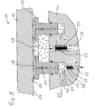
- FIG. 4 shows a schematic, sectional partial view of another Embodiment of the bending compensating roll 10, in which the viscous damping the relative to the yoke 14 moving support source 16 is variable.
- FIG. 5 shows an enlarged illustration of a detail from FIG. 4.
- the ERF or ferrofluid effect can also be used to increase it the damping properties of the support source 16 are used.
- Intrusion e.g. a tension on the guide bushing 36 of the support source 16
- the viscosity of the fluid between the guide bush 36 and the yoke 14 are greatly increased, resulting in a significant increase the viscous damping of the relative to the yoke 14 moving support source 16 leads.
- the guide bushing 36 should in this case become electrical to the support source head otherwise, in case of mixed friction of the support source head on the rotating roll shell 12 to a voltage drop or short circuit can occur. Also this damping property is actively controllable.
- FIG. 6 shows a schematic sectional partial view of another Embodiment of the bending compensating roll 10, in which the support source 16 a damper 38 is associated, on the one hand on the support source head 16 'and on the other hand supported on the yoke 14.
- the damper 38 contains electrorheological fluid (ERF) or ferrofluid, via its influenceable by a corresponding field viscosity the Damping properties on relative to the yoke 14 movable support source head 16 'and / or the vibration characteristics of the roll shell 12 are variable.
- the Damper 38 one containing the electrorheological fluid or ferrofluid Cylinder 40 and a cylinder 40 arranged in the piston 42nd
- the outer cross section of the piston 42 is less than the inner cross section of the cylinder 40, so that in operation displaced by the piston 42 Fluid the radial area between the piston 42 and the Cylinder inside can happen.
- the viscosity of the electrorheological fluid or ferrofluid affecting field is in the radial area between the Piston 42 and the cylinder inside generated. It can, for example between the piston 42 and the cylinder 38 in that shown in FIG Way a voltage U are applied, which then correspondingly is variable.
- the damper 38 is on the one hand via its cylinder 40 and on the other hand over a guided from the interior of the cylinder 40 to the outside piston rod 44th at the support source head 16 'and yoke 14 supported. Basically, however Also conceivable such an embodiment, wherein the damper 38 via the piston rod at the support source head 16 'and above the cylinder 40 at Yoke 14 is supported.
- the damper 38 is over each a ball joint 46 on the support source head 16 'and yoke 14 supported.
- the damper 38th at least substantially within the pressure space 20 of the support source 16 arranged.
- FIG. 8 shows a schematic sectional partial representation of another Embodiment of the bending compensating roller 10, wherein the support source 16 is designed as a ring element.
- the throttle point 52 is variably adjustable in that the viscosity of a through this throttle point 52 flowing Elektrorhetreun fluid or Ferrofluids via an electric or magnetic field is variable.
- the throttle point 52 comprises an arranged in the drain line 50 electrical conductor 26 via the field can be generated. For example, a Voltage U2 are applied, which then variably adjustable accordingly is.
- the support source 16 has in its the shell inner surface 54 facing Support surface 56 at least one annular pocket 58 and the yoke 14th facing an annular pressure surface 60.
- the pressure surface 60 limited a pressure chamber 20, on the one hand with a pressure medium supply line 62 and on the other hand via a throttle 64 with the pocket 58 in connection stands.
- a throttle point 66 is integrated, the This is variably adjustable, that the viscosity of a through this Throttle 66 flowing electrorheological fluid or ferrofluid is variable via an electric or magnetic field.
- the throttle point 66 comprises in the present case, for example, one in the pressure medium supply line 62 arranged electrical conductor 68, via which the field can be generated.
- a voltage U 1 to the electrical conductor 68 be created, which is variable accordingly.
- the annular pocket 58 is conveniently divided by transverse webs. In this case, each pocket section with the pressure chamber 20 via a throttle 64 may be connected.
- FIG. 9 shows an embodiment comparable to FIG. 8, FIG except the directly connected to the pressure chamber 20 pressure sensor 70 but also in addition to the interior 48 connected Pressure transducer 72 is provided.
- the support element 16 forming ring element in particular be executed and operated as in the publications DE 44 29 499 C1 and DE 195 40 791 C1 is described.
Landscapes
- Engineering & Computer Science (AREA)
- General Engineering & Computer Science (AREA)
- Physics & Mathematics (AREA)
- Fluid Mechanics (AREA)
- Mechanical Engineering (AREA)
- Rolls And Other Rotary Bodies (AREA)
- Fluid-Damping Devices (AREA)
- Vibration Prevention Devices (AREA)
- Magnetic Bearings And Hydrostatic Bearings (AREA)
Abstract
Description
- Figur 1
- eine schematische, geschnittene Teildarstellung einer beispielhaften Ausführungsform einer Biegeausgleichswalze, bei der die Stützquelle ausschließlich mit dem Elektrorheologischen Fluid (ERF) bzw. Ferrofluid betrieben ist,
- Figur 2
- eine schematische geschnittene Teildarstellung einer weiteren Ausführungsform der Biegeausgleichswalze, bei der die Stützquelle in einem Zweikreissystem betrieben ist,
- Figur 3
- eine Abwandlung der Biegeausgleichswalze gemäß Figur 2, bei der die Drosselstelle einen elektrischen Leiter umfasst,
- Figur 4
- eine schematische geschnittene Teildarstellung einer weiteren Ausführungsform der Biegeausgleichswalze, bei der die viskose Dämpfung der relativ zum Joch bewegten Stützquelle variierbar ist,
- Figur 5
- eine vergrößerte Darstellung eines Ausschnitts aus der Figur 4,
- Figur 6
- eine schematische geschnittene Teildarstellung einer weiteren Ausführungsform der Biegeausgleichswalze mit einem der Stützquelle zugeordneten, einerseits am Stützquellenkopf und andererseits am Joch abgestützten Dämpfer,
- Figur 7
- eine vergrößerte Darstellung eines Ausschnitts aus der Figur 6,
- Figur 8
- eine schematische geschnittene Teildarstellung einer weiteren Ausführungsform der Biegeausgleichswalze, bei der die Stützquelle als Ringelement ausgeführt ist, und
- Figur 9
- eine mit der Ausführungsform gemäß Figur 8 vergleichbare Ausführungsform, wobei außer dem mit dem Druckraum verbundenen Druckaufnehmer jedoch zusätzlich noch ein mit dem Innenraum verbundener Druckaufnehmer vorgesehen ist.
- 10
- Biegeausgleichswalze
- 12
- Walzenmantel
- 14
- Joch
- 16
- Stützquelle
- 16'
- Stützquellenkopf
- 18
- gemeinsame Versorgungsleitung
- 20
- Druckraum
- 22
- Verbindungsleitung
- 24
- Drosselstelle
- 26
- elektrische Leitung
- 28
- Druckaufnehmer
- 30
- Öltasche
- 32
- Verbindungsleitung
- 34
- Drosselstelle
- 36
- Führungsbuchse
- 38
- Dämpfer
- 40
- Zylinder
- 42
- Kolben
- 44
- Kolbenstange
- 46
- Kugelgelenk
- 48
- Innenraum
- 50
- Ablaufleitung
- 52
- Drosselstelle
- 54
- Mantelinnenfläche
- 56
- Stützfläche
- 58
- ringförmige Tasche
- 60
- ringförmige Druckfläche
- 62
- Druckmittelzuleitung
- 64
- Drossel
- 66
- Drosselstelle
- 68
- elektrischer Leiter
- 70
- Druckaufnehmer
- 72
- Druckaufnehmer
Claims (34)
- Biegeausgleichswalze (10) mit einem umlaufenden Walzenmantel (12), einem den Walzenmantel (12) axial durchsetzenden drehfesten Joch (14) und wenigstens einer zwischen dem Joch (14) und dem Walzenmantel (12) angeordneten Stützquelle (16),
dadurch gekennzeichnet, dass die Stützquelle (16) zumindest teilweise mit einem Elektrorheologischen Fluid (ERF) und/oder Ferrofluid betrieben ist, dessen Viskosität über ein elektrisches bzw. magnetisches Feld variierbar ist. - Biegeausgleichswalze nach Anspruch 1,
dadurch gekennzeichnet, dass über das die Viskosität des Elektrorheologischen Fluids (ERF) bzw. Ferrofluids beeinflussende Feld der hydraulische Druck variierbar ist. - Biegeausgleichswalze nach Anspruch 2,
dadurch gekennzeichnet, dass eine Druckregelung vorgesehen ist. - Biegeausgleichswalze nach einem der vorhergehenden Ansprüche,
dadurch gekennzeichnet, dass über das die Viskosität des Elektrorheologischen Fluids (ERF) bzw. Ferrofluids beeinflussende Feld der Volumenstrom variierbar ist. - Biegeausgleichswalze nach Anspruch 4,
dadurch gekennzeichnet, dass eine Volumenstromregelung vorgesehen ist. - Biegeausgleichswalze nach einem der vorhergehenden Ansprüche,
dadurch gekennzeichnet, dass über das die Viskosität des Elektrorheologischen Fluids (ERF) bzw. Ferrofluids beeinflussende Feld die Dämpfungseigenschaften an der Stützquelle variierbar sind. - Biegeausgleichswalze nach einem der vorhergehenden Ansprüche,
dadurch gekennzeichnet, dass über das die Viskosität des Elektrorheologischen Fluids (ERF) bzw. Ferrofluids beeinflussende Feld und die entsprechenden Änderungen im Druckraum der Stützquelle die Schwingungseigenschaften des Walzenmantels variierbar sind. - Biegeausgleichswalze nach einem der vorhergehenden Ansprüche,
dadurch gekennzeichnet, dass die Stützquelle (16) ausschließlich mit dem Elektrorheologischen Fluid (ERF) bzw. Ferrofluid betrieben ist. - Biegeausgleichswalze nach einem der vorhergehenden Ansprüche,
dadurch gekennzeichnet, dass mehrere Stützquellen (16) über eine gemeinsame Versorgungsleitung (18) mit dem Elektrorheologischen Fluid (ERF) bzw. Ferrofluid versorgt sind, in der der Systemdruck gehalten wird. - Biegeausgleichswalze nach Anspruch 9,
dadurch gekennzeichnet, dass zwischen dem Druckraum (20) einer jeweiligen Stützquelle (16) und der gemeinsamen Versorgungsleitung (18) jeweils eine Verbindungsleitung (22) vorgesehen ist, in die eine Drosselstelle (24) integriert ist, in der zur Erzeugung des Feldes ein elektrischer Leiter (26) angeordnet ist. - Biegeausgleichswalze nach einem der vorhergehenden Ansprüche,
dadurch gekennzeichnet, dass ein direkt mit dem Druckraum (20) der Stützquelle (16) verbundener Druckaufnehmer (28) vorgesehen ist. - Biegeausgleichswalze nach einem der vorhergehenden Ansprüche,
dadurch gekennzeichnet, dass der zur Druckregelung vorgesehene elektrische Regler außerhalb der Walze angeordnet ist. - Biegeausgleichswalze nach einem der vorhergehenden Ansprüche,
dadurch gekennzeichnet, dass die Stützquelle (16) in einem Zweikreissystem betrieben ist, in dem das Elektrorheologische Fluid (ERF) bzw. Ferrofluid nur der Druckregelung dient und die Schmierung der Stützquelle (16) mit herkömmlichem Öl erfolgt. - Biegeausgleichswalze nach Anspruch 13,
dadurch gekennzeichnet, dass die Öltaschen (30) der Stützquelle (16) mit konstantem Volumenstrom versorgt sind. - Biegeausgleichswalze nach Anspruch 13 oder 14,
dadurch gekennzeichnet, dass das Elektrorheologische Fluid (ERF) bzw. Ferrofluid für die Regelung des Drucks im Druckraum (20) der Stützquelle (16) in einem separaten Kreislauf fließt. - Biegeausgleichswalze nach einem der Ansprüche 13 bis 15,
dadurch gekennzeichnet, dass zwischen dem Druckraum (20) einer jeweiligen Stützquelle (16) und dem Tank der ERF- bzw. Ferrofluid-Versorgung jeweils eine Verbindungsleitung (32) vorgesehen ist, in die eine Drosselstelle (34) zum Halten des Drucks im Druckraum (20) integriert ist. - Biegeausgleichswalze nach Anspruch 16,
dadurch gekennzeichnet, dass die Drosselstelle (34) eine Blende oder Kapillare umfasst. - Biegeausgleichswalze nach Anspruch 17,
dadurch gekennzeichnet, dass die Drosselstelle (34) einen elektrischer Leiter (26) umfasst. - Biegeausgleichswalze nach einem der vorhergehenden Ansprüche,
dadurch gekennzeichnet, dass über die Viskosität des Elektrorheologischen Fluids (ERF) bzw. Ferrofluids zwischen der Führungsbuchse (36) der Stützquelle (16) und dem Joch (14) die viskose Dämpfung der relativ zum Joch (14) bewegten Stützquelle (16) variierbar ist. - Biegeausgleichswalze nach einem der vorhergehenden Ansprüche,
dadurch gekennzeichnet, dass der Stützquelle (16) ein Dämpfer (38) zugeordnet ist, der einerseits am Stützquellenkopf (16') und anderseits am Joch (14) abgestützt ist und Elektrorheologisches Fluid (ERF) bzw. Ferrofluid enthält, über dessen durch ein entsprechendes Feld beeinflussbare Viskosität die Dämpfungseigenschaften am relativ zum Joch (14) bewegbaren Stützquellenkopf (16') und/oder die Schwingungseigenschaften des Walzenmantels (12) variierbar sind. - Biegeausgleichswalze nach Anspruch 20,
dadurch gekennzeichnet, dass der Dämpfer (38) einen das Elektrorheologische Fluid (ERF) bzw. Ferrofluid enthaltenden Zylinder (40) und einen im Zylinder (40) angeordneten Kolben (42) umfasst, dessen Außenquerschnitt geringer als der Innenquerschnitt des Zylinders (40) ist, so dass im Betrieb durch den Kolben (42) verdrängtes Fluid den radialen Bereich zwischen dem Kolben (42) und der Zylinderinnenseite passieren kann. - Biegeausgleichswalze nach Anspruch 21,
dadurch gekennzeichnet, dass das jeweilige, die Viskosität des Elektrorheologischen Fluids (ERF) bzw. Ferrofluids beeinflussende Feld in dem radialen Bereich zwischen dem Kolben (42) und der Zylinderinnenseite erzeugt wird. - Biegeausgleichswalze nach einem der vorhergehenden Ansprüche,
dadurch gekennzeichnet, dass der Dämpfer (38) einerseits über seinen Zylinder (40) und andererseits über eine vom Innern des Zylinders (40) nach außen geführte Kolbenstange (44) am Stützquellenkopf (16') bzw. Joch (14) oder umgekehrt abgestützt ist. - Biegeausgleichswalze nach einem der vorhergehenden Ansprüche,
dadurch gekennzeichnet, dass der Dämpfer (38) jeweils über ein Kugelgelenk (40) am Stützquellenkopf (16') bzw. Joch (14) abgestützt ist. - Biegeausgleichswalze nach einem der vorhergehenden Ansprüche,
dadurch gekennzeichnet, dass der Dämpfer (38) zumindest im Wesentlichen innerhalb des Druckraums (20) der Stützquelle (16) angeordnet ist. - Biegeausgleichswalze nach einem der vorhergehenden Ansprüche,
dadurch gekennzeichnet, dass die Stützquelle (16) als Ringelement ausgeführt ist. - Biegeausgleichswalze nach Anspruch 26,
dadurch gekennzeichnet, dass der vom Ringelement umschlossene Innenraum (48) mit einer Ablaufleitung (50) in Verbindung steht, in die eine Drosselstelle (52) integriert ist, die dadurch variabel einstellbar ist, dass die Viskosität eines durch diese Drosselstelle (52) fließenden Elektrorheologischen Fluids (ERF) bzw. Ferrofluids über ein elektrisches bzw. magnetisches Feld variierbar ist. - Biegeausgleichswalze nach Anspruch 27,
dadurch gekennzeichnet, dass die Drosselstelle (52) einen in der Ablaufleitung (50) angeordneten elektrischen Leiter (26) umfasst, über den das Feld erzeugbar ist. - Biegeausgleichswalze nach einem der vorhergehenden Ansprüche,
dadurch gekennzeichnet, dass die Stützquelle (16) in ihrer der Mantelinnenfläche (54) zugewandten Stützfläche (56) wenigstens eine ringförmige Tasche (58) und dem Joch (14) zugewandt eine ringförmige Druckfläche (60) aufweist, die einen Druckraum (20) begrenzt, der einerseits mit einer Druckmittelzuleitung (62) und andererseits über eine Drossel (64) mit der Tasche (58) in Verbindung steht. - Biegeausgleichswalze nach Anspruch 29,
dadurch gekennzeichnet, dass in die Druckmittelzuleitung (62) eine Drosselstelle (66) integriert ist, die dadurch variabel einstellbar ist, dass die Viskosität eines durch diese Drosselstelle (66) fließenden Elektrorheologischen Fluids (ERF) bzw. Ferrofluids über ein elektrisches bzw. magnetisches Feld variierbar ist. - Biegeausgleichswalze nach Anspruch 30,
dadurch gekennzeichnet, dass die Drosselstelle (66) einen in der Druckmittelzuleitung (62) angeordneten elektrischen Leiter (68) umfasst, über den das Feld erzeugbar ist. - Biegeausgleichswalze nach einem der vorhergehenden Ansprüche,
dadurch gekennzeichnet, dass die ringförmige Tasche (58) durch Querstege unterteilt und jeder Taschenabschnitt mit dem Druckraum (20) über eine Drossel (64) verbunden ist. - Biegeausgleichswalze nach einem der vorhergehenden Ansprüche,
dadurch gekennzeichnet, dass ein direkt mit dem Druckraum (20) der Stützquelle (16) verbundener Druckaufnehmer (70) vorgesehen ist. - Biegeausgleichswalze nach einem der vorhergehenden Ansprüche,
dadurch gekennzeichnet, dass ein direkt mit dem Innenraum (48) verbundener Druckaufnehmer (72) vorgesehen ist.
Applications Claiming Priority (2)
| Application Number | Priority Date | Filing Date | Title |
|---|---|---|---|
| DE102004022377A DE102004022377A1 (de) | 2004-05-06 | 2004-05-06 | Biegeausgleichswalze |
| DE102004022377 | 2004-05-06 |
Publications (2)
| Publication Number | Publication Date |
|---|---|
| EP1593864A1 true EP1593864A1 (de) | 2005-11-09 |
| EP1593864B1 EP1593864B1 (de) | 2008-03-12 |
Family
ID=34926268
Family Applications (1)
| Application Number | Title | Priority Date | Filing Date |
|---|---|---|---|
| EP04019976A Expired - Lifetime EP1593864B1 (de) | 2004-05-06 | 2004-08-23 | Biegeausgleichswalze |
Country Status (3)
| Country | Link |
|---|---|
| US (1) | US20050250632A1 (de) |
| EP (1) | EP1593864B1 (de) |
| DE (2) | DE102004022377A1 (de) |
Cited By (1)
| Publication number | Priority date | Publication date | Assignee | Title |
|---|---|---|---|---|
| CN115870963A (zh) * | 2023-02-03 | 2023-03-31 | 极限人工智能有限公司 | 基于电流变液的万向球头、机械臂、机器人及其工作方法 |
Families Citing this family (3)
| Publication number | Priority date | Publication date | Assignee | Title |
|---|---|---|---|---|
| CH695089A5 (de) * | 2001-09-18 | 2005-12-15 | Main Man Inspiration Ag | Giessrolle für eine Zweirollen-Giessmaschine. |
| US7258654B2 (en) * | 2004-03-05 | 2007-08-21 | Rohm and Haas Dënmark Finance A/S | Compliant pressure roller with uniform nip pressure |
| DE102004034830A1 (de) * | 2004-07-19 | 2006-03-16 | Voith Paper Patent Gmbh | Biegeausgleichswalze |
Citations (6)
| Publication number | Priority date | Publication date | Assignee | Title |
|---|---|---|---|---|
| FI79571B (fi) * | 1988-11-07 | 1989-09-29 | Valmet Paper Machinery Inc | Foerfarande foer pressbehandling av materialbanor, boejningsreglerad vals och i samband med denna anvaend ventilanordning. |
| DE4429499C1 (de) | 1994-08-19 | 1995-11-16 | Kleinewefers Gmbh | Durchbiegungssteuerbare Walze für einen Kalander o. dgl. |
| WO1998017862A1 (en) * | 1996-10-23 | 1998-04-30 | Valmet Corporation | A tubular roll provided with hydraulically loaded glide bearings |
| WO2002064886A2 (en) * | 2001-02-09 | 2002-08-22 | Metso Paper, Inc. | Method for controlling the operation of a paper, board or tissue production line |
| EP1281879A2 (de) * | 2001-07-31 | 2003-02-05 | Voith Paper Patent GmbH | Durchbiegungseinstellwalze |
| EP1411254A1 (de) * | 2002-10-17 | 2004-04-21 | Voith Paper Patent GmbH | Walze, insbesondere Mittelwalze eines Kalanders, mit einer Tilgeranordnung |
Family Cites Families (25)
| Publication number | Priority date | Publication date | Assignee | Title |
|---|---|---|---|---|
| CH579723A5 (de) * | 1974-06-27 | 1976-09-15 | Escher Wyss Ag | |
| CH618504A5 (de) * | 1977-06-02 | 1980-07-31 | Escher Wyss Ag | |
| AT381514B (de) * | 1981-01-15 | 1986-10-27 | Escher Wyss Ag | Einrichtung an einem walzgeruest |
| DE3311998A1 (de) * | 1983-04-02 | 1984-10-04 | J.M. Voith Gmbh, 7920 Heidenheim | Bandpresseinheit, vorzugsweise als nasspresse einer papiermaschine |
| CH662619A5 (de) * | 1983-09-28 | 1987-10-15 | Escher Wyss Ag | Durchbiegungseinstellwalze. |
| FR2553312B1 (fr) * | 1983-10-14 | 1987-05-22 | Clecim Sa | Procede de reglage de l'epaisseur et du profil d'un produit plat en cours de laminage |
| DE3410136C2 (de) * | 1984-03-20 | 1987-04-30 | Küsters, Eduard, 4150 Krefeld | Regeleinrichtung für die Liniendruckverteilung in Walzenanordnungen für Druckbehandlung von Warenbahnen |
| CH672823A5 (de) * | 1987-03-10 | 1989-12-29 | Escher Wyss Ag | |
| US4897905A (en) * | 1989-02-13 | 1990-02-06 | Beloit Corporation | Controlled deflection roll using inert gasses and independent lubrication system |
| US5386769A (en) * | 1989-10-03 | 1995-02-07 | Rinne; Erkki | Adjustable press roller using silicone elastomer as pressure medium |
| CH681863A5 (de) * | 1990-06-25 | 1993-06-15 | Escher Wyss Ag | |
| DE4426513C2 (de) * | 1994-07-27 | 1997-07-17 | Voith Sulzer Papiermasch Gmbh | Durchbiegungseinstellwalze |
| DE19505379C1 (de) * | 1995-02-17 | 1996-03-28 | Voith Sulzer Papiermasch Gmbh | Durchbiegungseinstellwalze |
| DE29508422U1 (de) * | 1995-05-20 | 1995-08-10 | Voith Sulzer Papiermaschinen GmbH, 89522 Heidenheim | Walze mit Schwingungsdämpfer |
| DE29509545U1 (de) * | 1995-06-10 | 1995-09-21 | Voith Sulzer Papiermaschinen GmbH, 89522 Heidenheim | Walze mit Schwingungsdämpfer |
| CA2187381C (en) * | 1995-11-02 | 1999-05-11 | Rolf Van Haag | Deflection controllable roller for use in a calender |
| US6257133B1 (en) * | 1999-03-15 | 2001-07-10 | International Paper | Method and apparatus for controlling cross directional nip dynamics |
| DE10050596A1 (de) * | 2000-10-12 | 2002-04-18 | Voith Paper Patent Gmbh | Durchbiegungseinstellwalze |
| DE10136271A1 (de) * | 2001-07-25 | 2003-02-13 | Voith Paper Patent Gmbh | Durchbiegungseinstellwalze |
| DE10136270A1 (de) * | 2001-07-25 | 2003-03-13 | Voith Paper Patent Gmbh | Durchbiegungseinstellwalze |
| DE10231207A1 (de) * | 2002-07-10 | 2004-01-22 | Voith Paper Patent Gmbh | Biegeausgleichswalze |
| FI112110B (fi) * | 2002-10-16 | 2003-10-31 | Metso Paper Inc | Paperi- /kartonkikoneen tai jälkikäsittelykoneen taipumakompensoitu tela |
| US7258654B2 (en) * | 2004-03-05 | 2007-08-21 | Rohm and Haas Dënmark Finance A/S | Compliant pressure roller with uniform nip pressure |
| US7465264B2 (en) * | 2004-07-12 | 2008-12-16 | Rohm And Haas Denmark Finance A/S | Axially compliant pressure roller utilizing non-newtonian fluid |
| DE102004034830A1 (de) * | 2004-07-19 | 2006-03-16 | Voith Paper Patent Gmbh | Biegeausgleichswalze |
-
2004
- 2004-05-06 DE DE102004022377A patent/DE102004022377A1/de not_active Withdrawn
- 2004-08-23 DE DE502004006488T patent/DE502004006488D1/de not_active Expired - Lifetime
- 2004-08-23 EP EP04019976A patent/EP1593864B1/de not_active Expired - Lifetime
-
2005
- 2005-05-04 US US11/122,410 patent/US20050250632A1/en not_active Abandoned
Patent Citations (7)
| Publication number | Priority date | Publication date | Assignee | Title |
|---|---|---|---|---|
| FI79571B (fi) * | 1988-11-07 | 1989-09-29 | Valmet Paper Machinery Inc | Foerfarande foer pressbehandling av materialbanor, boejningsreglerad vals och i samband med denna anvaend ventilanordning. |
| DE4429499C1 (de) | 1994-08-19 | 1995-11-16 | Kleinewefers Gmbh | Durchbiegungssteuerbare Walze für einen Kalander o. dgl. |
| DE19540791C1 (de) | 1994-08-19 | 1997-04-03 | Voith Sulzer Finishing Gmbh | Durchbiegungssteuerbare Walze für einen Kalander o. dgl. |
| WO1998017862A1 (en) * | 1996-10-23 | 1998-04-30 | Valmet Corporation | A tubular roll provided with hydraulically loaded glide bearings |
| WO2002064886A2 (en) * | 2001-02-09 | 2002-08-22 | Metso Paper, Inc. | Method for controlling the operation of a paper, board or tissue production line |
| EP1281879A2 (de) * | 2001-07-31 | 2003-02-05 | Voith Paper Patent GmbH | Durchbiegungseinstellwalze |
| EP1411254A1 (de) * | 2002-10-17 | 2004-04-21 | Voith Paper Patent GmbH | Walze, insbesondere Mittelwalze eines Kalanders, mit einer Tilgeranordnung |
Cited By (2)
| Publication number | Priority date | Publication date | Assignee | Title |
|---|---|---|---|---|
| CN115870963A (zh) * | 2023-02-03 | 2023-03-31 | 极限人工智能有限公司 | 基于电流变液的万向球头、机械臂、机器人及其工作方法 |
| CN115870963B (zh) * | 2023-02-03 | 2023-08-25 | 极限人工智能有限公司 | 基于电流变液的万向球头、机械臂、机器人及其工作方法 |
Also Published As
| Publication number | Publication date |
|---|---|
| DE502004006488D1 (de) | 2008-04-24 |
| DE102004022377A1 (de) | 2005-12-08 |
| US20050250632A1 (en) | 2005-11-10 |
| EP1593864B1 (de) | 2008-03-12 |
Similar Documents
| Publication | Publication Date | Title |
|---|---|---|
| DE102005058254B4 (de) | Magnetorheologische Vorrichtung und magnetorheologisches System sowie Verfahren zur Verwendung derselben | |
| WO2008141787A1 (de) | Schwingungsdämpfer | |
| EP3014129B1 (de) | Hydraulikzylinder mit kolbenstange | |
| DE102019117233A1 (de) | Druckrückführkolben mit Ringschulter | |
| EP3158217B1 (de) | Hydrolager sowie kraftfahrzeug mit einem derartigen hydrolager | |
| EP1593864B1 (de) | Biegeausgleichswalze | |
| DE102007042910A1 (de) | Zylinder-Kolben-Anordnung auf Basis elektrorheologischer/magnetorheologischer Flüssigkeiten | |
| EP1731669A1 (de) | Biegeausgleichswalze | |
| DE102006005776A1 (de) | Pneumatikzylinder zur Positionssteuerung | |
| EP3221612B1 (de) | Hydrolager sowie kraftfahrzeug mit einem derartigen hydrolager | |
| EP1279767B1 (de) | Durchbiegungseinstellwalze | |
| DE102008054715A1 (de) | Lagerung für eine rotierbare und durch Schwingungsanregung in Richtung iher Rotationsachse bewegbare Walze, insbesondere Brustwalze und Verfahren zur Steuerung der Betriebsweise einer derartigen Walze | |
| EP1769119B1 (de) | Biegeausgleichswalze | |
| EP0731015A1 (de) | Lenkventil | |
| DE102021204441A1 (de) | Ventilanordnung für eine Dämpfervorrichtung sowie Dämpfervorrichtung mit der Ventilanordnung | |
| DE102010012635A1 (de) | Achseinheit | |
| EP3221613A1 (de) | Hydrolager sowie kraftfahrzeug mit einem derartigen hydrolager | |
| EP2935957B1 (de) | Viskositätsabhängig einstellbares stromregelventil | |
| EP1870516A1 (de) | Walze | |
| DE1946768C3 (de) | Druckregelventil | |
| EP2577078A1 (de) | Walze und verfahren zur vermeidung ihrer schwingungen | |
| DE102005025950A1 (de) | Biegeausgleichswalze | |
| WO2004038096A1 (de) | Durchbiegungseinstellwalze | |
| DE102008017714B4 (de) | Rotationslager und Textilmaschine mit einem Rotationslager | |
| EP0791524A1 (de) | Lenkventil |
Legal Events
| Date | Code | Title | Description |
|---|---|---|---|
| PUAI | Public reference made under article 153(3) epc to a published international application that has entered the european phase |
Free format text: ORIGINAL CODE: 0009012 |
|
| AK | Designated contracting states |
Kind code of ref document: A1 Designated state(s): AT BE BG CH CY CZ DE DK EE ES FI FR GB GR HU IE IT LI LU MC NL PL PT RO SE SI SK TR |
|
| AX | Request for extension of the european patent |
Extension state: AL HR LT LV MK |
|
| 17P | Request for examination filed |
Effective date: 20051206 |
|
| AKX | Designation fees paid |
Designated state(s): DE FI SE |
|
| RAP1 | Party data changed (applicant data changed or rights of an application transferred) |
Owner name: VOITH PATENT GMBH |
|
| GRAP | Despatch of communication of intention to grant a patent |
Free format text: ORIGINAL CODE: EPIDOSNIGR1 |
|
| GRAS | Grant fee paid |
Free format text: ORIGINAL CODE: EPIDOSNIGR3 |
|
| GRAA | (expected) grant |
Free format text: ORIGINAL CODE: 0009210 |
|
| AK | Designated contracting states |
Kind code of ref document: B1 Designated state(s): DE FI SE |
|
| REF | Corresponds to: |
Ref document number: 502004006488 Country of ref document: DE Date of ref document: 20080424 Kind code of ref document: P |
|
| REG | Reference to a national code |
Ref country code: SE Ref legal event code: TRGR |
|
| PLBI | Opposition filed |
Free format text: ORIGINAL CODE: 0009260 |
|
| PLAX | Notice of opposition and request to file observation + time limit sent |
Free format text: ORIGINAL CODE: EPIDOSNOBS2 |
|
| 26 | Opposition filed |
Opponent name: METSO PAPER, INC. Effective date: 20081212 |
|
| PLAF | Information modified related to communication of a notice of opposition and request to file observations + time limit |
Free format text: ORIGINAL CODE: EPIDOSCOBS2 |
|
| PLBB | Reply of patent proprietor to notice(s) of opposition received |
Free format text: ORIGINAL CODE: EPIDOSNOBS3 |
|
| PLCK | Communication despatched that opposition was rejected |
Free format text: ORIGINAL CODE: EPIDOSNREJ1 |
|
| APAJ | Date of receipt of notice of appeal modified |
Free format text: ORIGINAL CODE: EPIDOSCNOA2O |
|
| APBM | Appeal reference recorded |
Free format text: ORIGINAL CODE: EPIDOSNREFNO |
|
| APBP | Date of receipt of notice of appeal recorded |
Free format text: ORIGINAL CODE: EPIDOSNNOA2O |
|
| APAH | Appeal reference modified |
Free format text: ORIGINAL CODE: EPIDOSCREFNO |
|
| APBQ | Date of receipt of statement of grounds of appeal recorded |
Free format text: ORIGINAL CODE: EPIDOSNNOA3O |
|
| PGFP | Annual fee paid to national office [announced via postgrant information from national office to epo] |
Ref country code: SE Payment date: 20110824 Year of fee payment: 8 |
|
| PGFP | Annual fee paid to national office [announced via postgrant information from national office to epo] |
Ref country code: FI Payment date: 20120813 Year of fee payment: 9 |
|
| PGFP | Annual fee paid to national office [announced via postgrant information from national office to epo] |
Ref country code: DE Payment date: 20120822 Year of fee payment: 9 |
|
| APBU | Appeal procedure closed |
Free format text: ORIGINAL CODE: EPIDOSNNOA9O |
|
| REG | Reference to a national code |
Ref country code: SE Ref legal event code: EUG |
|
| PG25 | Lapsed in a contracting state [announced via postgrant information from national office to epo] |
Ref country code: SE Free format text: LAPSE BECAUSE OF NON-PAYMENT OF DUE FEES Effective date: 20120824 |
|
| PLBN | Opposition rejected |
Free format text: ORIGINAL CODE: 0009273 |
|
| STAA | Information on the status of an ep patent application or granted ep patent |
Free format text: STATUS: OPPOSITION REJECTED |
|
| 27O | Opposition rejected |
Effective date: 20130124 |
|
| REG | Reference to a national code |
Ref country code: DE Ref legal event code: R100 Ref document number: 502004006488 Country of ref document: DE Effective date: 20130124 |
|
| PG25 | Lapsed in a contracting state [announced via postgrant information from national office to epo] |
Ref country code: FI Free format text: LAPSE BECAUSE OF NON-PAYMENT OF DUE FEES Effective date: 20130823 Ref country code: DE Free format text: LAPSE BECAUSE OF NON-PAYMENT OF DUE FEES Effective date: 20140301 |
|
| REG | Reference to a national code |
Ref country code: DE Ref legal event code: R119 Ref document number: 502004006488 Country of ref document: DE Effective date: 20140301 |