EP1594948B1 - Procédé et dispositifs permettant de déplacer une sonde sans lésion à travers une matière cellulaire biologique - Google Patents
Procédé et dispositifs permettant de déplacer une sonde sans lésion à travers une matière cellulaire biologique Download PDFInfo
- Publication number
- EP1594948B1 EP1594948B1 EP03775404A EP03775404A EP1594948B1 EP 1594948 B1 EP1594948 B1 EP 1594948B1 EP 03775404 A EP03775404 A EP 03775404A EP 03775404 A EP03775404 A EP 03775404A EP 1594948 B1 EP1594948 B1 EP 1594948B1
- Authority
- EP
- European Patent Office
- Prior art keywords
- probe
- cell
- cells
- cell material
- movement
- Prior art date
- Legal status (The legal status is an assumption and is not a legal conclusion. Google has not performed a legal analysis and makes no representation as to the accuracy of the status listed.)
- Expired - Lifetime
Links
Images



Classifications
-
- B—PERFORMING OPERATIONS; TRANSPORTING
- B01—PHYSICAL OR CHEMICAL PROCESSES OR APPARATUS IN GENERAL
- B01L—CHEMICAL OR PHYSICAL LABORATORY APPARATUS FOR GENERAL USE
- B01L3/00—Containers or dishes for laboratory use, e.g. laboratory glassware; Droppers
- B01L3/02—Burettes; Pipettes
- B01L3/021—Pipettes, i.e. with only one conduit for withdrawing and redistributing liquids
-
- C—CHEMISTRY; METALLURGY
- C12—BIOCHEMISTRY; BEER; SPIRITS; WINE; VINEGAR; MICROBIOLOGY; ENZYMOLOGY; MUTATION OR GENETIC ENGINEERING
- C12M—APPARATUS FOR ENZYMOLOGY OR MICROBIOLOGY; APPARATUS FOR CULTURING MICROORGANISMS FOR PRODUCING BIOMASS, FOR GROWING CELLS OR FOR OBTAINING FERMENTATION OR METABOLIC PRODUCTS, i.e. BIOREACTORS OR FERMENTERS
- C12M33/00—Means for introduction, transport, positioning, extraction, harvesting, peeling or sampling of biological material in or from the apparatus
- C12M33/02—Means for introduction, transport, positioning, extraction, harvesting, peeling or sampling of biological material in or from the apparatus by impregnation, e.g. using swabs or loops
-
- C—CHEMISTRY; METALLURGY
- C12—BIOCHEMISTRY; BEER; SPIRITS; WINE; VINEGAR; MICROBIOLOGY; ENZYMOLOGY; MUTATION OR GENETIC ENGINEERING
- C12M—APPARATUS FOR ENZYMOLOGY OR MICROBIOLOGY; APPARATUS FOR CULTURING MICROORGANISMS FOR PRODUCING BIOMASS, FOR GROWING CELLS OR FOR OBTAINING FERMENTATION OR METABOLIC PRODUCTS, i.e. BIOREACTORS OR FERMENTERS
- C12M35/00—Means for application of stress for stimulating the growth of microorganisms or the generation of fermentation or metabolic products; Means for electroporation or cell fusion
-
- G—PHYSICS
- G01—MEASURING; TESTING
- G01N—INVESTIGATING OR ANALYSING MATERIALS BY DETERMINING THEIR CHEMICAL OR PHYSICAL PROPERTIES
- G01N15/00—Investigating characteristics of particles; Investigating permeability, pore-volume or surface-area of porous materials
- G01N15/10—Investigating individual particles
- G01N15/1031—Investigating individual particles by measuring electrical or magnetic effects
- G01N15/12—Investigating individual particles by measuring electrical or magnetic effects by observing changes in resistance or impedance across apertures when traversed by individual particles, e.g. by using the Coulter principle
-
- G—PHYSICS
- G01—MEASURING; TESTING
- G01N—INVESTIGATING OR ANALYSING MATERIALS BY DETERMINING THEIR CHEMICAL OR PHYSICAL PROPERTIES
- G01N15/00—Investigating characteristics of particles; Investigating permeability, pore-volume or surface-area of porous materials
- G01N15/10—Investigating individual particles
- G01N15/14—Optical investigation techniques, e.g. flow cytometry
-
- A—HUMAN NECESSITIES
- A61—MEDICAL OR VETERINARY SCIENCE; HYGIENE
- A61B—DIAGNOSIS; SURGERY; IDENTIFICATION
- A61B10/00—Instruments for taking body samples for diagnostic purposes; Other methods or instruments for diagnosis, e.g. for vaccination diagnosis, sex determination or ovulation-period determination; Throat striking implements
- A61B10/02—Instruments for taking cell samples or for biopsy
- A61B10/0233—Pointed or sharp biopsy instruments
-
- A—HUMAN NECESSITIES
- A61—MEDICAL OR VETERINARY SCIENCE; HYGIENE
- A61B—DIAGNOSIS; SURGERY; IDENTIFICATION
- A61B10/00—Instruments for taking body samples for diagnostic purposes; Other methods or instruments for diagnosis, e.g. for vaccination diagnosis, sex determination or ovulation-period determination; Throat striking implements
- A61B10/02—Instruments for taking cell samples or for biopsy
- A61B10/0233—Pointed or sharp biopsy instruments
- A61B10/0283—Pointed or sharp biopsy instruments with vacuum aspiration, e.g. caused by retractable plunger or by connected syringe
-
- A—HUMAN NECESSITIES
- A61—MEDICAL OR VETERINARY SCIENCE; HYGIENE
- A61B—DIAGNOSIS; SURGERY; IDENTIFICATION
- A61B10/00—Instruments for taking body samples for diagnostic purposes; Other methods or instruments for diagnosis, e.g. for vaccination diagnosis, sex determination or ovulation-period determination; Throat striking implements
- A61B10/02—Instruments for taking cell samples or for biopsy
- A61B2010/0208—Biopsy devices with actuators, e.g. with triggered spring mechanisms
-
- B—PERFORMING OPERATIONS; TRANSPORTING
- B01—PHYSICAL OR CHEMICAL PROCESSES OR APPARATUS IN GENERAL
- B01L—CHEMICAL OR PHYSICAL LABORATORY APPARATUS FOR GENERAL USE
- B01L2200/00—Solutions for specific problems relating to chemical or physical laboratory apparatus
- B01L2200/06—Fluid handling related problems
- B01L2200/0647—Handling flowable solids, e.g. microscopic beads, cells, particles
-
- B—PERFORMING OPERATIONS; TRANSPORTING
- B01—PHYSICAL OR CHEMICAL PROCESSES OR APPARATUS IN GENERAL
- B01L—CHEMICAL OR PHYSICAL LABORATORY APPARATUS FOR GENERAL USE
- B01L2300/00—Additional constructional details
- B01L2300/08—Geometry, shape and general structure
- B01L2300/0832—Geometry, shape and general structure cylindrical, tube shaped
- B01L2300/0838—Capillaries
-
- B—PERFORMING OPERATIONS; TRANSPORTING
- B01—PHYSICAL OR CHEMICAL PROCESSES OR APPARATUS IN GENERAL
- B01L—CHEMICAL OR PHYSICAL LABORATORY APPARATUS FOR GENERAL USE
- B01L2400/00—Moving or stopping fluids
- B01L2400/04—Moving fluids with specific forces or mechanical means
- B01L2400/0403—Moving fluids with specific forces or mechanical means specific forces
- B01L2400/0415—Moving fluids with specific forces or mechanical means specific forces electrical forces, e.g. electrokinetic
-
- B—PERFORMING OPERATIONS; TRANSPORTING
- B01—PHYSICAL OR CHEMICAL PROCESSES OR APPARATUS IN GENERAL
- B01L—CHEMICAL OR PHYSICAL LABORATORY APPARATUS FOR GENERAL USE
- B01L2400/00—Moving or stopping fluids
- B01L2400/04—Moving fluids with specific forces or mechanical means
- B01L2400/0403—Moving fluids with specific forces or mechanical means specific forces
- B01L2400/043—Moving fluids with specific forces or mechanical means specific forces magnetic forces
-
- B—PERFORMING OPERATIONS; TRANSPORTING
- B01—PHYSICAL OR CHEMICAL PROCESSES OR APPARATUS IN GENERAL
- B01L—CHEMICAL OR PHYSICAL LABORATORY APPARATUS FOR GENERAL USE
- B01L2400/00—Moving or stopping fluids
- B01L2400/04—Moving fluids with specific forces or mechanical means
- B01L2400/0475—Moving fluids with specific forces or mechanical means specific mechanical means and fluid pressure
- B01L2400/0487—Moving fluids with specific forces or mechanical means specific mechanical means and fluid pressure fluid pressure, pneumatics
-
- G—PHYSICS
- G01—MEASURING; TESTING
- G01N—INVESTIGATING OR ANALYSING MATERIALS BY DETERMINING THEIR CHEMICAL OR PHYSICAL PROPERTIES
- G01N1/00—Sampling; Preparing specimens for investigation
- G01N1/28—Preparing specimens for investigation including physical details of (bio-)chemical methods covered elsewhere, e.g. G01N33/50, C12Q
- G01N1/286—Preparing specimens for investigation including physical details of (bio-)chemical methods covered elsewhere, e.g. G01N33/50, C12Q involving mechanical work, e.g. chopping, disintegrating, compacting, homogenising
-
- G—PHYSICS
- G01—MEASURING; TESTING
- G01N—INVESTIGATING OR ANALYSING MATERIALS BY DETERMINING THEIR CHEMICAL OR PHYSICAL PROPERTIES
- G01N15/00—Investigating characteristics of particles; Investigating permeability, pore-volume or surface-area of porous materials
- G01N15/10—Investigating individual particles
- G01N15/14—Optical investigation techniques, e.g. flow cytometry
- G01N2015/1486—Counting the particles
-
- G—PHYSICS
- G01—MEASURING; TESTING
- G01N—INVESTIGATING OR ANALYSING MATERIALS BY DETERMINING THEIR CHEMICAL OR PHYSICAL PROPERTIES
- G01N15/00—Investigating characteristics of particles; Investigating permeability, pore-volume or surface-area of porous materials
- G01N15/10—Investigating individual particles
- G01N15/14—Optical investigation techniques, e.g. flow cytometry
- G01N2015/1493—Particle size
Definitions
- the invention relates to methods for moving a probe through a biological cell material formed from animal or human cells, manipulation and / or examination devices that are set up to carry out such methods, cell manipulators having at least one such manipulation and / or examination device , and applications of said methods.
- So far cannulas or syringe needles are used as injection tools.
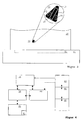
- FIG. 9 shows the tip of a conventional injection cannula 10 'in an enlarged side view.
- the injection cannula 10 ' has a hollow cannula body i1' whose free end 12 'is chamfered and optionally ground to form a point.
- a straight and reproducible injection channel for example, in a tissue
- the conventional injection cannula 10 'for precision applications has an extremely small diameter in the sub-mm range and the end 12' terminates in a sub-micron tip
- the conventional use of the cannula injury-free insertion into a tissue is basically excluded. As soon as the tip hits cells in a tissue with the previously used high puncture speed, they are mechanically injured, for example crushed or torn.
- the object of the invention is to provide improved methods for moving a probe through a cell material formed from biological cells, which addresses the problems of conventional injection methods and which are in principle capable of meeting the cell technology requirements listed above ,
- the object of the invention is, in particular, improved methods for introducing a probe to provide in cell tissue or cell clusters with which cells or other substances can be introduced into the cell material, cells or cell components can be removed from the cell material and / or measurements can be carried out in the cell material.
- the object of the invention is also to provide improved manipulation and / or examination devices for carrying out such methods and injection devices equipped with at least one such device, with which the disadvantages of conventional injection tools are overcome.
- Another object of the invention is to provide new applications of introducing probes into cellular material.
- the invention is based in particular on the feature of moving a probe through a cell material with biological cells such that the probe displaces the cells without injury.
- the probe is actuated in the cell material such that the cells are pushed apart from or separated from the surface of the probe, thus creating space for the probe, leaving the cells unchanged in their physical and chemical state during displacement or separation.
- An injury-free displacement of cells is especially given when the cells in direct contact with the probe body or cells lying deeper in the cell material are deformed or change their spatial position during the movement of the probe however, do not emit chemical signals in the form of messenger substances or substance secretions.
- Cell material is generally understood to mean an accumulation of cells which are connected to their surroundings via adhesion contacts (macromolecular chemical compounds, not van der Waals bonds).
- the cell material is, for example, a composite or combination of single cells, a tissue (association of similarly differentiated cells) or an organ.
- the non-liquid composite of single cells may contain additional synthetic components, for example a synthetic matrix or support material.
- the probe is generally a foreign body or object of a material delimitable with respect to the cellular material, preferably with a solid surface.
- the probe may in particular comprise a manipulation and / or examination device such as an injection capillary or electrical leads introduced into the cell material (for example brain).
- the invention is based in particular on the following considerations of the inventors. It was firstly recognized that the hitherto diverse precipitating reactions, for example, of injected cells in a tissue or a cell structure are due to the fact that the introduction of an injection tool injures or destroys cells in the existing cell material and thus causes wound effects. In a cell or tissue wounding chemical signals (emission of molecular messengers) or cell-supported processes, such. As a fibroblast immigration, a Fibronektinausso precise or the like. Generated. The reaction of injured cells influences the action of the injected cells or additives. For example, stem cells behave in the environment of a Cell injury unlike stem cells in an intact cell material.
- the o. G. Requirements are fully met. Neither the target tissue nor the individual cells or substances to be used are damaged or impaired.
- the physical, chemical and mechanical state of the cells can be fully characterized. Harmful contacts between cells and surfaces of foreign bodies are avoided, cellular signals are suppressed by surface contact.
- the cell manipulation is ideally gentle.
- the probe can be guided precisely to a specific location in the cell material. It is also particularly advantageous that limitations on the size of the probe, as they existed in conventional injection cannulas, are overcome.
- An inventively moved by the cell material tool allows accurate and reproducible detection of the number and type of introduced into the cell material cells or additives.
- the probe is moved at a propelling speed that is less than or equal to a reference velocity passing through the physiological binding rate or natural cell movement of biological cells is determined (binding rate of cells).
- the natural cell movement (English: cell locomotion) includes the change of location of a complete cell on a solid surface or in cell material by a rearrangement of adhesion contacts of cell organs (membrane organs, for example Membranausstülpitch), as described for example by M. Abercrombie et al. in the publication " The Locomotion Of Fibroblasts In Culture “(” Experimental Cell Research ", Vol. 67, 1971, pp.
- the probe When setting the propulsion speed, the probe can advantageously be moved without injury by cells in a naturally given composite.
- the propulsion speed is adapted to the cell movement that takes place permanently in the tissue.
- certain types of immune cells eg, macrophages
- the inventors have found that, surprisingly, this displacement movement can also be achieved with probes which are considerably larger than immune cells and have macroscopic dimensions in the sub-millimeter to centimeter range when the aforementioned propulsion speed is set.
- macromolecular bonds for example, membrane-bound macromolecules of the integrin and catheter family
- the physiological reference speed is known per se (see, for example, US Pat. BG Fuhr et al. in "Biol. Chem.”, 1998, Vol. 379, pp. 1161-1173 ) or measurable on animal or human cells.
- the binding rate of interest can be derived, for example, by measuring the dynamics of adhesion patterns of individual cells on artificial surfaces.
- the movement of the probe at the desired propelling speed can advantageously be carried out even with the least expenditure of force. This allows the use of low power drive devices.
- the propulsion force is formed by a mechanical compressive force, advantages for the transmission of propulsive force to the probe may result. If the propulsive force is formed by forces in electric or magnetic fields, advantages for the construction of an injection device can result, since the propulsive forces can be exerted via a remote action.
- the propulsive force can be formed by intercellular forces.
- the probe may migrate through the cellular material without an external drive under the action of the adhesive bonds in the cell material. If, for example, by a surface treatment of the probe on one side has a stronger tendency to form adhesive bonds than on another side, the probe can be driven by the generation of the adhesive bonds, which may be due to the shape of the probe and / or the other og propulsive forces is supported.
- the probe is moved in a direction parallel to the orientation of an elongate shape of the probe.
- the displacement must only take place on the front side of the probe, which is a very small surface area compared to the rest of the surface.
- this embodiment has the advantage of being compatible with conventional injection techniques using syringes, cannulas or capillaries.
- the probe may be combined with any means available for manipulating cells or cell suspensions.
- a substance to be introduced into the cell material with the probe.
- known per se liquid conveyors such. As pumps or the like. Be used.
- a lateral movement of the probe may be provided, in which a direction of movement is set, which depends on the z. B. deviates elongated shape of the probe.
- a lateral movement of the probe may generally also include a radial extension of the probe body in the cell material (expansion movement).
- At least one cell is introduced into the cell material with the probe, since the cell, when injected into the cell material, finds it in a physiologically intact condition.
- the at least one cell is embedded in the interior of the uninjured cell material.
- stem cells can be implanted in tissue in order to achieve tissue-specific differentiation to cause the stem cells. Degeneration or tumor formation can be suppressed.
- the method according to the invention also enables the injection of biological cells in a frozen state. After cryopreservation, one or more cells in the frozen state can be embedded in the cell material and thawed there. Immediately during thawing, the cellular processes are started under the physiological conditions in the cell material.
- At least one cell is removed from the cell material with the probe.
- the probe forms a biopsy tool. This embodiment may provide benefits for obtaining unmodified physiological cells.
- the inventive principle of injury-free displacement of cells allows the use of probes with dimensions that also allow integration of sensors. According to a variant of the invention, it is therefore provided that the probe detects properties of the cell material, of injected cells or of extracted cells.
- the propelling speed of the probe is selected in a speed range of 0.1 ⁇ m / h to 1 mm / h, preferably in the range of 1 ⁇ m / h to 500 ⁇ m / h.
- This velocity range are the rates of binding of the assembly and degradation of macromolecular bonds, which are typically mediated by membrane-bound macromolecules of the integrin and catheter family.
- the preferred speed ranges correspond to the rates of cell movement of in particular fibroblasts, macrophages, lymphocytes, chondrocytes or tumor cells.
- the position of the probe can be adjusted with a high accuracy of up to +/- 1 micron.
- the propulsion rates in the above ranges correspond to the active endogenous velocities of movement of cells in and on tissue.
- the movement of the probe thus causes a permanent attachment and remodeling of the cells in the immediate vicinity of the probe surface, which is promoted by the permanently acting propulsion force displacement of the cells.
- the method according to the invention is carried out on cell material which is located outside of an animal or human organism.
- the cell material may be placed under suitable culture conditions on a solid support which provides the counterforce to exert the propulsive force.
- the cell material and the probe can be positioned with high precision.
- the probe is adapted to be at least partially introduced into the cell material.
- the probe has a probe body which is movable by the cell material and in particular has a rounded or flattened surface on at least one front side, which forms a front end or front displacement or separation part when the probe moves through the cell material relative to the direction of movement ,
- the front has a contour that is free of tips, steps, edges, cutting and the like.
- the front has a mathematically continuous curvature contour, which can be described as a section of a surface of a sphere, an ellipsoid, a toroid or an overlay of these.
- the provision of the rounded or flattened surface on at least one front side has the advantage that injuries are avoided when inserting the probe according to the method according to the invention in the cell material, since the propulsion force acts uniformly over the entire rounding of the front side.
- the probe differs fundamentally from conventional injection tools, such. As syringe needles, where the injury is necessary given by the leadership of a section through the cell material.
- the probe front has in individual areas of the rounded surface a local radius of curvature which is greater than 10 ⁇ m.
- the rounded or flattened surface is larger than the cell types in the typically treated cell materials, especially cell types in tissue. This reduces the probability of injury during the movement of the probe.
- Particular advantages may arise with a local radius of curvature which is greater than 20 microns, preferably greater than 0.1 mm.
- the radius of curvature is less than 5 mm, preferably less than 2 mm. Alternatively, it can be very large, so that the front side is substantially flattened.
- the rounded surface forms a coating with a material (bonding material) which promotes adherence of cells to the surface.
- the bonding material forms the probe body, at least the front of the probe body or a coating at least on the front side of the probe body. It consists, for example, of fibronectin or collagen.
- This embodiment of the invention may have advantages in terms of increasing the rate of binding in the displacing movement of the probe through the cell material.
- the binding material may alternatively have a roughening with characteristic feature sizes in the sub-micron range, so that the binding of the cell material is promoted to the probe.
- the use of an adhesion-promoting material also represents a significant and fundamental difference between the tool according to the invention and conventional injection needles.
- the functional part generally represents a structural component of the probe body adapted for a particular technical function of the probe.
- the functional part is integrated in the probe body, so that the injury-free displacement movement is not disturbed.
- a cavity which is adapted for receiving and / or conducting cells or additives in or from the cell material.
- the cavity formed in the probe body on the one hand has at least one opening which is formed in a surface of the tool body.
- a connection of the cavity may be provided to an external sample reservoir.
- the functional part can comprise at least one sensor in the probe body, which is set up to detect chemical or physical properties of cells or substances in the cell material or in the interior of the probe body. If the at least one sensor is located in the cavity of the probe body, there may be benefits to monitoring an injection or biopsy.
- the functional part may further comprise at least one electrical conductor which extends into the rounded front of the probe.
- the conductor may be fused into the probe and form a measuring electrode. It is also possible to provide at least one light guide, for example for spectroscopic measurements in the cell material.
- the probe body is a straight, elongated shape along a straight axis (capillary, tube, hollow needle) having a first end, which is the rounded front, and a second end formed with a Reservoir device is connected.
- the first end may comprise a rounding off of the capillary wall (annular rounding) or the end of the probe body (spherical rounding).
- the probe body is preferably a syringe needle having a free end at which the wall of the syringe needle is rounded.
- the receiving tool has a receiving surface which serves as a substrate or carrier for at least one cell and has a concave or convex shape.
- a concave receiving surface may have advantages in terms of the demarcation of the picking tool from the environment, such. B. of other probe parts or of cell material.
- the advantage of the convex receiving surface is its optimal adaptation to the displacing movement of the probe according to the invention by the cell material.
- the receiving tool is arranged in a capillary-shaped probe or in a probe with a groove-shaped recess, the provision of a suspension or culture fluid in the vicinity of the receiving tool and the at least one cell located thereon is advantageously facilitated. Further advantages for the storage of cells from the capillary or the channel-shaped recess arise when the receiving tool is slidably disposed in the probe.
- the probe body can be formed by a shaped body whose entire surface is rounded like the o. G. Front is.
- the probe body can thus be completely enveloped by the cell material without mechanical connection with additional external devices through the cell material.
- the probe body may, for example, be formed completely spherical.
- the probe body is formed by a spherical receiving tool with a rod-shaped holder, with which advantageously a driving force can be transmitted from a drive device to the receiving tool.
- the probe is equipped with at least one spacer with which the probe body is placed on the cell carrier. As a result, the accuracy and stability of the positioning of the probe on the cell carrier can advantageously be increased.
- the probe body is equipped with at least one force element, there may be advantages for the targeted and directed action of an external driving force.
- the power element is a mechanical support, there are advantages in terms of reliability and precision of power transmission.
- the force element comprises a magnetic element, a contactless manipulation of the probe in the cell material is advantageously made possible.
- Another object of the invention is a cell manipulator (in particular a working device such as an injection, biopsy and / or examination device for the processing of cell material, wherein the cell manipulator comprises at least one probe according to the invention and at least one drive means for moving the at least one probe.
- the cell manipulator has the particular advantage that the probe can be manipulated with the drive device with high accuracy and reproducibility in the cell material. ⁇ br/> ⁇ br/> If the drive device comprises a piezoelectric drive, advantages for the controllability of the probe movement are obtained Alternatively, the drive device can be formed by a magnetic drive In addition, the drive device may comprise a spring drive, so that there are advantages in terms of a particularly simple Aufba u of the manipulation device.
- the cell manipulator is equipped with a positioning device for controlling the drive device, a detector device for detecting the position of the at least one tool and / or a carrier device for receiving cell material.
- Preferred applications of the invention are in vitro cell culture, tissue engineering in biotechnology, the creation of tissue models for pharmacology and medical therapy.
- FIG. 1 The inventive movement of a probe through a cell material is in FIG. 1 the example of the injection of a cell in a tissue sample shown.
- a probe 10 according to the invention is illustrated in a schematic sectional view.
- the probe 10 comprises a probe body 11 which is formed by a hollow needle or pipette tip.
- a hollow channel 31 In the interior of the probe body 11 extends as a functional part 30 a hollow channel 31 with an opening 32 at the end 12.
- the opposite end of the probe body 11 is provided with a piezoelectric drive device 50 connected.
- the probe 10 is at a distance from a cell material 20 which is arranged on a carrier 80.
- the cell material 20 is, for example, a cell cluster or spheroid made up of 50 to 500 contiguous cells 21, which are connected to one another via adhesive contacts.
- a stem cell is to be injected into this cell material 20 with the procedure described below in order to cause it to undergo cell-specific differentiation in the cell material.
- the probe 10 is pushed into the cell material 20, whereby the cells 21 of the cell material are displaced.
- adhesion contacts with the cells 12 are formed.
- the adhesion contacts are continuously rearranged, so that first the end and, with advancing propulsion, the adjoining part of the probe body 11 are surrounded by the cells 21.
- a continuous growth of the tool surface with the cells 21 takes place.
- the propelling motion is stopped.
- a stem cell 22 is moved through the hollow channel 31 into the cell material 20. This movement takes place, for example, by flushing with a suspension liquid.
- the probe 10 After injection of the stem cells into the cell material, the probe 10 is withdrawn. The retraction movement likewise takes place at such a low speed that the cells 21 can rearrange without injury until the displaced space around the injected stem cell 22 is refilled (partial image C of FIG. 1 ).
- the drive means 50 is mounted on the carrier 80 and the relative movement between the cell material 20 and the probe 10 is generated on the carrier side, while the probe 10 is firmly positioned.
- Partial image (A) shows a conically tapered probe body 11. This form advantageously favors the displacement of cells in the cell material.
- the front sides 13 are rounded in accordance with the principles explained above.
- the probe body 11 consists, for example, of glass, an inert metal (eg platinum) or an inert plastic material (eg polyimide).
- Range a 0.1 .mu.m to 10 .mu.m for the injection of particularly small cells or synthetic particles or larger dimensions of z.
- B. a 100 microns to 5 mm for injection z.
- B. of embryonic stem cells can be selected, wherein the dimension b is selected according to the wall thickness of the probe body 11 correspondingly larger.
- the probe 10 may be equipped with a sensor 33.
- an impedance sensor 33 is provided at the end 12.
- the impedance sensor 33 comprises two semi-circular electrodes (impedance electrodes) which are mounted on the surface of the front side 13, for example by vapor deposition.
- the impedance electrodes may be mounted on the outside of the probe body 11 at the end 12 thereof.
- Via electrical connection lines (not shown) along the probe body 11, the electrodes of the impedance sensor 33 are connected to a control device.
- an impedance signal is generated by the detuning of the impedance between the impedance electrodes, which gives in a conventional manner information about the number, size and electrical properties of the passing cell.
- impedance sensors 33 may alternatively or additionally be provided on the inside of the hollow channel 31. Furthermore, partial image (B) at the end 12 of the probe body 11 formed with a constant diameter shows a bulging front side 13.
- Partial image (C) of FIG. 2 schematically illustrates an adhesion-promoting coating 14 on the end 12 of the probe body 11.
- This compound coating is preferably only on the rounded, displacing front side the probe 10 is provided while the surface of the remainder of the probe body 11 is preferably coated with adhesion-reducing coating to promote sliding between the displaced cells.
- the compound coating consists, for example, of fibronectin.
- silanization or occupancy with biological macromolecules for example PolyHema
- the inner surface of the hollow channel may be coated adhesion-reducing in this way.
- the cross-sectional shape of the capillary-shaped probe body is preferably round.
- a flattened ellipse shape may be provided which allows a preferred direction for lateral movement in a direction of movement perpendicular to the longitudinal axis of the probe body 11.
- the capillary-shaped probe body is cut obliquely at its free end 12, so that a paddle-shaped receiving tool 15 is formed.
- the inner wall of the hollow channel 31 of the capillary 11 forms at the free end 12 a receiving surface 16, which is bounded laterally by upstanding edges 17.
- the probe 10 is placed on a support 80 (eg bottom of a culture support) or a cell material 20 located thereon.
- the probe 10 is advanced in the cell material 20 (see double-headed arrow) until a desired cell 21 has been transferred to the receiving tool 15.
- the cell transfer can be promoted by the natural natural motion of the cell 21.
- the probe body 11 of the probe 10 comprises a receiving tool 15 which is arranged at the end of a probe shaft.
- the receiving tool 15 has a spherical shape, the surface of which forms a receiving surface for a cell 21 to be transferred from a carrier 80.
- the receiving tool 15 has a diameter of z. B. 15 microns.
- the spherical receiving tool 15 can according to part of the figure F of FIG. 2 be combined with a capillary probe body 11.
- the receiving tool 15 is displaceable with the probe shaft 19 in the hollow channel 31 corresponding to the longitudinal axis of the capillary 11.
- the probe 10 is immersed in a culture liquid 81 above the carrier and approximated to the cell material 20 located thereon.
- the receiving tool 15 is advanced with a drive device (see below), wherein cell material 20 is possibly displaced without injury. Supported by the advancing movement and possibly by the natural cell movement, the cell 21 can be transferred to the receiving tool 15.
- Partial image F also illustrates the rounded shape of all parts of the free end 12 of the probe 10, so that it can be completely moved without injury by cell material according to the inventive method.
- the receiving tool is formed as a cylindrical plunger or parallelepiped slider which is slidably disposed in the hollow channel 31 of the capillary 11 (partial image G) or in an open, channel-shaped recess 34 of the probe body 11 (partial image H).
- the embodiments of the probe 10 according to the invention shown in the partial images F to H have the advantage that on the probe 10, a drop of liquid 81 may be formed on the probe 10 to protect cell material.
- a bowl-shaped or spoon-shaped design of the free end 12 of the probe 10 is illustrated in Part I.
- a receiving tool 15 is formed in the form of a part of a hollow sphere, on the inside of which the receiving surface 16 is provided for at least one cell 21.
- an opening 17 is provided at the bottom of the receiving tool 15 through which the cell 21 can be received. The recording takes place by a movement of the probe 10 relative to the carrier 80, possibly supported by the natural cell movement of the cell 21.
- a modified design can be dispensed with the openings 17 and instead provided a recording of cell material in the receiving tool 15 on the top be.
- Partial picture J the FIG. 2 FIG. 10 shows spacers 18 that may be provided on each of the probes of the invention at the free end 12 or at other positions of the probe body 11 to facilitate positioning on the support 80.
- a particular advantage is that the displacement movement of the probe 10 according to the invention by cell material can also be carried out with the spacers 18 without undesirably injuring cells.
- the diameter of the receiving tool 15 according to the partial images I and J is, for example, 0.2 mm.
- the diameter of the opening 17 may be, for example, 1 .mu.m to 0.5 mm.
- the sub-images K and L illustrate that the invention not only for receiving single cells, but also for the transfer of cell material, such.
- B. cell monolayers or cell cultures 20 can be used.
- a paddle-shaped receiving tool 15 is provided, which is formed analogously to part of image D and, for example.
- the width of the receiving surface 16 is, for example, 10 .mu.m to 50 mm.
- the lateral edges 17 effect a delimitation of the cell material received by the carrier 80 from its surroundings.
- Panel L shows the retraction of the probe 10 in a multi-layer cell system or tissue association in order to distinguish from this a layering of cells (cell layer 24) nondestructively and without a biochemical treatment.
- the propulsion (see arrow) of the tool takes place with the said physiological reference velocity of the cells.
- FIG. 3 shows a modified embodiment of the invention, in which the probe 10 (shown enlarged above) is completely surrounded by the cell material 20 without a mechanical connection to the outside.
- the cell material 20 is positioned on the carrier 80, in which a magnetic device 51 is integrated as a drive device.
- the probe 10 has a conical probe body 11 with fillets 13 on the abutting surfaces. The rounding in this case form several fronts.
- a permanent magnet 15 is integrated as a force element.
- the reference numeral 31 refers to a cavity in the probe body 11, which is filled, for example, with an active ingredient. Through an opening or a permeable wall of the probe body 11 For example, the active agent may emerge at the desired positions in the cellular material 20.
- the reference numeral 33 refers to a sensor integrated with the probe 10.
- the sensor 33 includes, for example, a pH sensor, glucose sensor or another sensor for biologically relevant properties (biosensor).
- the probe 10 according to FIG. 3 temporarily connected to an external reservoir, for example, to refill the cavity 31 with an active ingredient.
- a capillary-shaped probe is moved through the cell material 20 to the probe 10 and coupled to this according to the principles explained above.
- an electrical stimulator with an electrical energy reservoir can be arranged in the probe 10 as a functional unit, which is connected to an external voltage source via electrical lines if required. This connection is made by introducing electrical lines according to the displacement movement according to the invention.
- a cell manipulator comprises according to the block diagram in FIG. 4 at least one probe 10 and at least one drive means 50 for exerting a driving force on the probe 10.
- the drive means 50 includes z. B. piezocrystals with which the probe 10 can be positioned and moved in an analogous manner to known micromanipulator in different spatial directions with an accuracy of ⁇ 100 nm.
- the travel of the probe 10 can be between 0.1 mm and a few centimeters.
- the drive device 50 is connected to a positioning device 60.
- the positioning device 60 is a component that is mechanically stable and micrometer-accurate relative to the target cell system (cell material) fixable component, which allows to accomplish the slow movement of the probe into or out of the target cell system. Its task is to guarantee the stable position of the entire injection system in relation to the target cell system over the duration of the manipulation (hours, days or even weeks). This can be achieved by means of an adjustable three-point support on the culture system (see FIG. 5) or anchoring, for example, to the bone of the skull during cell injection into the brain.
- the positioning device 60 may also be connected to the carrier 80 (see dashed arrows).
- the carrier 80 is, for example, a culture dish (see FIG. 5 ) or a substrate in a culture system.
- the positioning device 60 is further connected to a control device 61 and a measuring and display device 62.
- the controller 61 serves to control the entire system and includes a processor or computer.
- the current and planned positions are carried out via sensors (strain gauges on actuators, 4-quadrant detection using a laser beam as in atomic force microscopy or in an analogous manner).
- the information is processed software-based and displayed in such a way that the real and planned movement is displayed on a monitor together with appropriate parameters. For this purpose, a camera system with microscopic magnification and a zoom function can be provided.
- the probe 10 is preferably connected to a sample reservoir 40, which contains a transport system 41 for moving a sample from the reservoir 40 into the probe 10.
- the sample to be injected into the cell material is, for example, a cell suspension.
- the transport system 41 is a known conveyors such as B. a precision syringe pump.
- the sample reservoir 40 for receiving the cells to be injected may be a Hamilton syringe or a container connected via a low-dead volume 3-way system.
- the transport system 41 presses a cell suspension into the injection tools (probe 10) via mechanical compression. Very small volumes are to be moved (speed a few ⁇ m / min). It could also rinses with washing solutions (speed 1 to several 100 microns / s) are performed. This can be achieved via programmable syringe pumps.
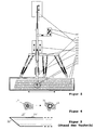
- FIG. 5 Further details of the cell manipulator are shown using the example of an in vitro system for biotechnology (tissue engineering).
- the aim is to inject into a cell tissue dressing 20 by means of a microcapillary (probe 10) one or more cells 22 from a cell reservoir 40.
- the probe 10 is connected to the cell reservoir 40 via a channel system.
- the probe 10 is connected to a Hamilton syringe (transport system 41 for the cell suspension 22), which is addressed via a processor or a computer control (not shown).
- the entire system is located on a working platform 63, which can not move relative to the tissue assembly 20 because it is fixedly connected to the culture dish 80 via the positioning device 60.
- the basic adjustment of the working platform 63 takes place with the positioning device 60.
- the propulsion system or drive device 50 for the probe 10 is a piezotube which can expand or contract in the manner indicated and thereby introduces or withdraws the probe 10 into the tissue structure 20. Shown is a target cell area 23 (dotted ring) into which just a cell 22 is inserted.
- a single cell detector system 33 On the shaft of the capillary probe 10 is a single cell detector system 33, with which the number of injected cells can be detected (shown here as an optical system).
- the cell manipulator accordingly FIG. 5 is operated as follows.
- the positioning device is brought into a fixed connection with the target tissue 20. This is done by fixing the positioning unit on the culture dish 80 or on the surface of an organism or a suitable part of the skeleton.
- the microinjection tool 10 is attached to the work platform 61 and roughly pre-adjusted so that it is located just before the target tissue or cell system 20 with its tip.
- the capillary of the probe 10 is filled with the nutrient solution, a physiological solution or another suitable fluid and introduced to the target tissue until it touches.
- the programmed propulsion of the microinjection tool is carried out in accordance with the speed of, for example, less than 1 ⁇ m / h up to a few 100 ⁇ m / h until the target region 23 is reached.
- the cells to be injected are rinsed from the reservoir into the microinjection tool and detected, counted and possibly characterized via the detector when passing the pierced part.
- the system can be guided into a new target area, so that cells are positioned three-dimensionally in the tissue in a predeterminable manner.
- the microinjection tool is removed again from the target tissue.
- the low velocity also referred to as "physiological velocity"
- physiological velocity allows the cells of the tissue at the tip of the injection tool to release the cell adhesion contacts, causing it to adhere An orderly displacement of the cells comes, but not their violation.
- FIG. 6 shows an example of a radial expansion movement of a capillary-shaped probe 10, the probe body 11 of an elastic material (for example, plastic, rubber) or a non-elastically expandable material (for example, relatively slidable blades made of steel or plastic o. The like.) Is.
- an elastic material for example, plastic, rubber
- a non-elastically expandable material for example, relatively slidable blades made of steel or plastic o. The like.
- FIG. 12 illustrates one embodiment of a plurality of probes 91 used in accordance with the invention, which form a manipulation tool 90.
- the probes are shaped elements 91 of the manipulation tool 90, each of which is displaceable individually with a drive device 92, which is attached to a base part (not shown).
- Each mold element 91 has an elongate cuboid shape with a top surface 93.
- the total number of top surfaces 93 form the surface of the manipulation tool 90 that is used to remove individual cells from the cell material 20.
- the mold elements 91 form a tool body.
- the tops 93 have typical dimensions in the range of 0.01 mm to 5 mm. They are flattened ('infinite' radius of curvature) and may have rounded edges.
- the mold elements 91 are oriented such that the topsides 93 form a matrix array of straight rows and columns.
- the displacement of the mold elements 91 relative to the base part takes place, for example, with servomotors or piezoelectric drives.
- the tool surface is structured. Separate Moldings 91 may be separable from the drive means 92 to remove cells.
- cells 21 from a cell material For the removal according to the invention of cells 21 from a cell material, this is first arranged on the tool surface, that is to say the entirety of the upper sides 93.
- growth from a cultivation medium in a culture vessel is provided.
- FIG. 7 For clarity, are in FIG. 7 only individual cells 21 are shown.
- the mold elements 91 corresponding to the selected cells are advanced. This feed takes place with the above-mentioned physiological reference speed, so that an injury-free displacement and separation of the selected cell takes place.
- a detachment of the formula element with the cell from the manipulation tool 90 can take place.
- An inventive storage of a cell 21 on a cell material may be provided analogously with the reverse sequence of steps.
- FIG. 7 also illustrates that the individual tops 93 of the mold elements 91 may be formed differently to additionally modify the cell material at the respective positions.
- microstructures may be used to improve the adhesion of the top surface 93 or additional structural elements, such as those shown in FIG. B.
- an inwardly formed in the mold member 91 buckle 93b for improved separation of a cell from the surrounding cell material may be provided.
- individual or all of the mold elements 91 may carry an adhesion-enhancing coating 93c.
- a manipulation tool 90 according to FIG. 7 can alternatively be used as an impression tool, as in the image sequence according to FIG. 8 is illustrated.
- a cell material 20 through which a tool is to be performed according to the inventive method.
- the manipulation tool 90 with the plurality of displaceable shaped elements 91 is arranged above the initially free surface of the cell material 20, the manipulation tool 90 with the plurality of displaceable shaped elements 91 is arranged.
- the manipulation tool 90 is brought closer to the cellular material 20 until the upper surfaces 93 facing downwards in this case touch the cellular material 20.
- partial image B an adjustment of the surface of the manipulation tool 90 by the targeted advancement of individual mold elements 91.
- the feed movement takes place with the above physiological reference velocity of biological cells.
- the individual form elements 91 displace the cells in the cell material without injury.
- the manipulation tool 90 is removed.
- the surface shape of the tool remains as a complementary structure in the cell material 20.
- the tops 93 of the mold elements 91 may be provided with a coating on which adhesion of cells is prevented. The coating takes place, for example, with the polymer Polyhema or PTFE.
- the gaps imprinted in the cell material can be filled in accordance with partial image D with other cells or a synthetic matrix material 25.
- epithelial cells having a predetermined structure may be associated with tissue cells.
Landscapes
- Health & Medical Sciences (AREA)
- Chemical & Material Sciences (AREA)
- Life Sciences & Earth Sciences (AREA)
- Engineering & Computer Science (AREA)
- Zoology (AREA)
- Organic Chemistry (AREA)
- Wood Science & Technology (AREA)
- Bioinformatics & Cheminformatics (AREA)
- Biochemistry (AREA)
- General Health & Medical Sciences (AREA)
- Genetics & Genomics (AREA)
- Biotechnology (AREA)
- General Engineering & Computer Science (AREA)
- Sustainable Development (AREA)
- Microbiology (AREA)
- Biomedical Technology (AREA)
- General Physics & Mathematics (AREA)
- Dispersion Chemistry (AREA)
- Pathology (AREA)
- Immunology (AREA)
- Analytical Chemistry (AREA)
- Physics & Mathematics (AREA)
- Cell Biology (AREA)
- Clinical Laboratory Science (AREA)
- Chemical Kinetics & Catalysis (AREA)
- Molecular Biology (AREA)
- Apparatus Associated With Microorganisms And Enzymes (AREA)
- Micro-Organisms Or Cultivation Processes Thereof (AREA)
- Immobilizing And Processing Of Enzymes And Microorganisms (AREA)
- Medicines Containing Material From Animals Or Micro-Organisms (AREA)
- Measuring Or Testing Involving Enzymes Or Micro-Organisms (AREA)
- Sampling And Sample Adjustment (AREA)
- Investigating Or Analysing Biological Materials (AREA)
- Optical Measuring Cells (AREA)
- Measurement Of The Respiration, Hearing Ability, Form, And Blood Characteristics Of Living Organisms (AREA)
Claims (37)
- Procédé de déplacement d'une sonde (10, 91) au travers d'une matière cellulaire (20) formée de cellules animales ou humaines (21), à l'exception de cellules souches embryonnaires humaines, et se trouvant à l'extérieur d'un organisme animal ou humain, caractérisé- en ce que la sonde (10, 91) est mue avec une vitesse d'avance de l'ordre de 0,1 µm/h à 1 mm/h,- la sonde (10, 90) refoulant les cellules (21) sans occasionner de lésion.
- Procédé selon la revendication 1, où la sonde (10, 91) est mue avec une vitesse d'avance inférieure ou égale à une vitesse de liaison moléculaire des cellules.
- Procédé selon la revendication 1 ou la revendication 2, où la sonde (10, 91) est soumise à une force d'avance exercée en permanence.
- Procédé selon la revendication 3, où la force d'avance comprend une ou plusieurs forces sélectionnées dans le groupe des forces de pression mécaniques, des forces électriques, des forces magnétiques et des forces intercellulaires.
- Procédé selon au moins une des revendications précédentes, où la sonde (10, 91) est mue au travers d'une matière cellulaire (20) comprenant une matière de liaison composée des cellules biologiques, ou des cellules biologiques et d'une matière matricielle.
- Procédé selon au moins une des revendications précédentes, où la sonde (10, 91) présente une forme étirée en longueur avec une direction longitudinale, et est mue dans une direction parallèle à la direction longitudinale.
- Procédé selon au moins une des revendications précédentes, où une substance est ajoutée par la sonde (10) à la matière cellulaire.
- Procédé selon la revendication 7, où au moins une cellule biologique (22) est ajoutée par la sonde (10) à la matière cellulaire.
- Procédé selon la revendication 8, où au moins une cellule biologique (22) en état de congélation est ajoutée à la matière cellulaire ;
- Procédé selon au moins une des revendications précédentes, où au moins une cellule est prélevée de la matière cellulaire par la sonde (10, 91).
- Procédé selon au moins une des revendications 8 à 10, où la ou les cellules exécutent un mouvement cellulaire naturel lors de l'ajout à la matière cellulaire ou du prélèvement de la matière cellulaire.
- Procédé selon au moins une des revendications précédentes, où des propriétés de la matière cellulaire sont saisies par la sonde (10).
- Procédé selon au moins une des revendications 1 à 5, où un formage de la matière cellulaire (20) est effectué avec une pluralité de sondes (91), qui forment chacune un élément de formage d'un outil de manipulation (90).
- Sonde (10, 91) à introduire dans une matière cellulaire (20) avec des cellules animales ou humaines (21), comportant un corps de sonde (11) déplaçable au travers de la matière cellulaire, caractérisée- en ce que le corps de sonde (11) présente une surface arrondie au moins sur une face avant (13, 93) orientée dans une direction de déplacement du corps de sonde (11) lors du déplacement au travers de la matière cellulaire (20), et en ce que la surface arrondie supporte un revêtement (14, 93c) favorisant une adhérence de cellules,- la sonde (10, 90) étant agencée pour refouler les cellules (21) sans occasionner de lésion lors du déplacement au travers de la matière cellulaire (20).
- Sonde selon la revendication 14, où la surface arrondie présente un rayon de courbure supérieur à 10 µm.
- Sonde selon au moins une des revendications 14 et 15, où le corps de sonde (11) est pourvu d'au moins une pièce fonctionnelle (30) comprenant au moins une cavité (31) dans le corps de sonde (11), avec une ouverture (32) formée dans une surface du corps de sonde, au moins un évidement (34) en forme de gouttière et/ou au moins un capteur (33) dans le corps de sonde.
- Sonde selon la revendication 16, où le capteur est disposé dans la cavité (31) du corps de sonde (11).
- Sonde selon au moins une des revendications 14 à 17, où le corps de sonde (11) comprend un capillaire avec une première extrémité (12) comportant le surface arrondie, et avec une deuxième extrémité reliée à un dispositif de réservoir (40).
- Sonde selon la revendication 18, où le capillaire (11) comporte un outil de réception (15) avec une surface de réception concave (14) à sa première extrémité (12).
- Sonde selon la revendication 19, où un outil de réception (15) avec une surface de réception convexe (14) est disposé dans le capillaire (11).
- Sonde selon la revendication 16, où un outil de réception (15) est disposé dans l'évidement en forme de gouttière (34).
- Sonde selon la revendication 20 ou la revendication 21, où l'outil de réception (15) est disposé de manière à être mobile dans le capillaire (11) ou l'évidement en forme de gouttière (34).
- Sonde selon au moins une des revendications 14 à 17, où le corps de sonde (11) comporte un corps de formage dont la surface est formée par la surface arrondie.
- Sonde selon la revendication 23, où le corps de sonde (11) comporte un corps de formage sphérique formant un outil de réception (15).
- Sonde selon la revendication 16, où la pièce fonctionnelle (30) comprend un outil de réception (15) en forme de coque avec une surface de réception (14) intérieure.
- Sonde selon la revendication 25, où la surface de réception (14) comporte une ouverture de passage (17).
- Sonde selon au moins une des revendications 14 à 26, où au moins un écarteur (18) est prévu à l'extrémité (12) du corps de sonde (11), avec lequel le corps de sonde (11) peut être déposé sur un support (80).
- Sonde selon au moins une des revendications 14 à 27, où le corps de sonde (11) comporte au moins un élément de force (15) agencé pour exercer une force d'avance extérieure.
- Sonde selon la revendication 28, où l'élément de force (15) comprend une fixation mécanique ou un élément magnétique.
- Manipulateur cellulaire, comprenant :- au moins une sonde (10, 91) selon au moins une des revendications 14 à 29, et- au moins un dispositif d'entraînement (50, 92) pour le déplacement de la sonde ou des sondes (10).
- Manipulateur cellulaire selon la revendication 30, comportant un dispositif de positionnement (60) pour le positionnement du dispositif d'entraînement (50, 92) et/ou d'un support (80) de la matière cellulaire (20).
- Manipulateur cellulaire selon la revendication 30 ou la revendication 31, comportant un dispositif de capteur pour la saisie de position de la sonde ou des sondes (10) et/ou de la cellule ou des cellules (21) de la matière cellulaire (20).
- Manipulateur cellulaire selon au moins une des revendications 30 à 32, où le support (80) est agencé pour la réception de matière cellulaire, le dispositif d'entraînement étant agencé pour déplacer la ou les sondes par rapport au support.
- Manipulateur cellulaire selon au moins une des revendications 30 à 33, où le dispositif d'entraînement (50, 92) comporte un entraînement piézoélectrique ou un entraînement par aimant.
- Manipulateur cellulaire selon au moins une des revendications 30 à 34, où le dispositif d'entraînement (50) est agencé pour déplacer la sonde (10) avec des vitesses de l'ordre de 0,1 µm/h à 1 mm/h.
- Manipulateur cellulaire selon au moins une des revendications 30 à 33, où le dispositif d'entraînement (92) est pourvu d'une pluralité de sondes (91) individuellement déplaçables.
- Utilisation d'une aiguille creuse, avec une extrémité libre arrondie supportant un revêtement (14) qui favorise une adhérence de cellules, pour un déplacement n'occasionnant pas de lésion dans de la matière cellulaire avec des cellules animales ou humaines, à l'exception de cellules souches embryonnaires humaines, la matière cellulaire se trouvant à l'extérieur d'un organisme animal ou humain.
Applications Claiming Priority (3)
| Application Number | Priority Date | Filing Date | Title |
|---|---|---|---|
| DE10307487 | 2003-02-21 | ||
| DE10307487A DE10307487A1 (de) | 2003-02-21 | 2003-02-21 | Verfahren und Vorrichtungen zur verletzungsfreien Bewegung einer Sonde durch biologisches Zellmaterial |
| PCT/EP2003/013582 WO2004074426A2 (fr) | 2003-02-21 | 2003-12-02 | Procede et dispositifs permettant de deplacer une sonde sans lesion a travers une matiere cellulaire biologique |
Publications (2)
| Publication Number | Publication Date |
|---|---|
| EP1594948A2 EP1594948A2 (fr) | 2005-11-16 |
| EP1594948B1 true EP1594948B1 (fr) | 2009-12-02 |
Family
ID=32841779
Family Applications (4)
| Application Number | Title | Priority Date | Filing Date |
|---|---|---|---|
| EP03785710A Expired - Lifetime EP1594949B1 (fr) | 2003-02-21 | 2003-12-02 | Procede et dispositif de formation d'une matiere cellulaire biologique |
| EP03775404A Expired - Lifetime EP1594948B1 (fr) | 2003-02-21 | 2003-12-02 | Procédé et dispositifs permettant de déplacer une sonde sans lésion à travers une matière cellulaire biologique |
| EP03782284A Withdrawn EP1594947A2 (fr) | 2003-02-21 | 2003-12-02 | Procede et dispositifs permettant le transfert de cellules biologiques entre un support et une sonde |
| EP11009651.8A Withdrawn EP2471900A3 (fr) | 2003-02-21 | 2003-12-02 | Procédé et dispositifs de transfert de cellules biologiques entre un support et une sonde |
Family Applications Before (1)
| Application Number | Title | Priority Date | Filing Date |
|---|---|---|---|
| EP03785710A Expired - Lifetime EP1594949B1 (fr) | 2003-02-21 | 2003-12-02 | Procede et dispositif de formation d'une matiere cellulaire biologique |
Family Applications After (2)
| Application Number | Title | Priority Date | Filing Date |
|---|---|---|---|
| EP03782284A Withdrawn EP1594947A2 (fr) | 2003-02-21 | 2003-12-02 | Procede et dispositifs permettant le transfert de cellules biologiques entre un support et une sonde |
| EP11009651.8A Withdrawn EP2471900A3 (fr) | 2003-02-21 | 2003-12-02 | Procédé et dispositifs de transfert de cellules biologiques entre un support et une sonde |
Country Status (8)
| Country | Link |
|---|---|
| US (4) | US7393629B2 (fr) |
| EP (4) | EP1594949B1 (fr) |
| KR (4) | KR100904760B1 (fr) |
| AT (2) | ATE450598T1 (fr) |
| AU (3) | AU2003294766A1 (fr) |
| DE (2) | DE10307487A1 (fr) |
| ES (1) | ES2373088T3 (fr) |
| WO (3) | WO2004074424A2 (fr) |
Families Citing this family (45)
| Publication number | Priority date | Publication date | Assignee | Title |
|---|---|---|---|---|
| EP1539923A2 (fr) * | 2002-08-27 | 2005-06-15 | Verigen AG | Bioreacteur avec zone de surface extensible destinee a la culture de cellules |
| DE10307487A1 (de) * | 2003-02-21 | 2004-09-09 | Fraunhofer-Gesellschaft zur Förderung der angewandten Forschung e.V. | Verfahren und Vorrichtungen zur verletzungsfreien Bewegung einer Sonde durch biologisches Zellmaterial |
| DE102004017476B4 (de) * | 2004-04-08 | 2009-03-26 | Fraunhofer-Gesellschaft zur Förderung der angewandten Forschung e.V. | Verfahren zur Herstellung einer Epithelzellen enthaltenden Zellzusammensetzung |
| EP1747264B1 (fr) | 2004-05-21 | 2012-09-12 | Fraunhofer-Gesellschaft zur Förderung der angewandten Forschung e.V. | Systemes de culture tissulaire et organique multicellulaires |
| DE102004053596B4 (de) * | 2004-11-05 | 2006-10-12 | Fraunhofer-Gesellschaft zur Förderung der angewandten Forschung e.V. | Verfahren und Vorrichtungen zur Bearbeitung einzelner biologischer Zellen |
| DE102006006269A1 (de) * | 2006-02-10 | 2007-08-23 | Fraunhofer-Gesellschaft zur Förderung der angewandten Forschung e.V. | Verfahren und Kultivierungseinrichtung zur Kultivierung biologischer Zellen |
| KR100712420B1 (ko) * | 2006-05-30 | 2007-04-27 | 전자부품연구원 | 그리퍼 및 그를 구비한 그립 장치 |
| DE102006045620B4 (de) * | 2006-09-25 | 2009-10-29 | Roland Dr. Kilper | Vorrichtung und Verfahren für Aufnahme, Transport und Ablage mikroskopischer Proben |
| EP1927652A1 (fr) * | 2006-11-29 | 2008-06-04 | Koninklijke Philips Electronics N.V. | Reseau de cellules ou matrice cellulaire et electroporation |
| US7850382B2 (en) * | 2007-01-18 | 2010-12-14 | Sanford, L.P. | Valve made from two materials and writing utensil with retractable tip incorporating same |
| DE102007004855B4 (de) | 2007-01-31 | 2014-03-27 | Fraunhofer-Gesellschaft zur Förderung der angewandten Forschung e.V. | Vorrichtung und Verfahren zur Deposition von biologischem Material in einem Zielsubstrat |
| US7488130B2 (en) | 2007-02-01 | 2009-02-10 | Sanford, L.P. | Seal assembly for retractable instrument |
| JP4517125B2 (ja) * | 2007-03-30 | 2010-08-04 | 国立大学法人九州大学 | 細胞の立体構造体の製造方法 |
| DE102007020376B4 (de) * | 2007-04-30 | 2009-03-05 | Fraunhofer-Gesellschaft zur Förderung der angewandten Forschung e.V. | Vorrichtung zum langsamen Durchdringen einer biologischen Barriere oder eines biologischen Gewebes mit einem spitzen Objekt |
| DE102007028422A1 (de) | 2007-06-20 | 2008-12-24 | Fraunhofer-Gesellschaft zur Förderung der angewandten Forschung e.V. | Verfahren und Vorrichtung zur Bildung einer dreidimensionalen Anordnung biologischer Zellen |
| WO2009002273A1 (fr) * | 2007-06-26 | 2008-12-31 | Agency For Science, Technology And Research | Chambre d'imagerie pourvue d'une fenêtre et d'une plate-forme à micro-aiguilles sollicitées magnetiquement l'une vers l'autre |
| DE102007036150A1 (de) * | 2007-08-02 | 2009-02-05 | Fraunhofer-Gesellschaft zur Förderung der angewandten Forschung e.V. | Verfahren und Vorrichtung zur Aufnahme von biologischen Zellen aus einer Stammzellenkultur |
| DE102007046516A1 (de) * | 2007-09-28 | 2009-04-02 | Fraunhofer-Gesellschaft zur Förderung der angewandten Forschung e.V. | Vorrichtung und Verfahren zur Konditionierung biologischer Zellen |
| AT506233B1 (de) | 2008-01-18 | 2009-07-15 | Leica Mikrosysteme Gmbh | Mikromanipulator für ein kryomikrotom |
| DE102008016217A1 (de) | 2008-03-28 | 2009-10-01 | Fraunhofer-Gesellschaft zur Förderung der angewandten Forschung e.V. | Verfahren und Vorrichtung zur Herstellung von gefrorenen biologischen Partikeln |
| US8226312B2 (en) * | 2008-03-28 | 2012-07-24 | Sanford, L.P. | Valve door having a force directing component and retractable instruments comprising same |
| US8221012B2 (en) * | 2008-11-07 | 2012-07-17 | Sanford, L.P. | Retractable instruments comprising a one-piece valve door actuating assembly |
| US8393814B2 (en) * | 2009-01-30 | 2013-03-12 | Sanford, L.P. | Retractable instrument having a two stage protraction/retraction sequence |
| US8556721B2 (en) * | 2009-11-16 | 2013-10-15 | Steelseries Aps | Apparatus and method for managing peripheral device communications |
| WO2012002967A1 (fr) * | 2010-07-01 | 2012-01-05 | Empire Technology Development Llc | Procédé et système de culture cellulaire et tissulaire |
| WO2012174112A2 (fr) * | 2011-06-13 | 2012-12-20 | The Trustees Of Columbia University In The City Of New York | Systèmes et procédés pour un réseau nanoscopique optique de détection et d'enregistrement des cellules électriquement excitables |
| EP2745360A4 (fr) | 2011-08-01 | 2015-07-08 | Univ Columbia | Conjugués de nanoparticules de diamant et de nanoparticules magnétiques ou métalliques |
| WO2013040446A1 (fr) | 2011-09-16 | 2013-03-21 | The Trustees Of Columbia University In The City Of New York | Génération d'horloge ghz de haute précision utilisant les états de spin dans le diamant |
| US9632045B2 (en) | 2011-10-19 | 2017-04-25 | The Trustees Of Columbia University In The City Of New York | Systems and methods for deterministic emitter switch microscopy |
| US10072927B2 (en) | 2016-01-07 | 2018-09-11 | Rarecyte, Inc. | Detecting a substrate |
| US11054346B2 (en) * | 2013-04-11 | 2021-07-06 | Rarecyte, Inc. | Detecting a substrate |
| US10416046B2 (en) * | 2013-04-11 | 2019-09-17 | Rarecyte, Inc. | Device, system, and method for selecting a target analyte |
| CN104099239B (zh) * | 2014-07-10 | 2016-04-20 | 中国农业科学院北京畜牧兽医研究所 | 一种显微操作持定针的制作方法 |
| FR3043093B1 (fr) * | 2015-10-30 | 2024-09-27 | Commissariat Energie Atomique | Dispositif de traitement d'au moins une cellule biologique, notamment en vue d'une delivrance intracellulaire |
| US10357767B1 (en) * | 2015-12-04 | 2019-07-23 | John L. Sternick | Sample scraping tool |
| EP3231860A1 (fr) * | 2016-04-14 | 2017-10-18 | Technische Universität Wien | Dispositif microfluidique |
| US11299705B2 (en) * | 2016-11-07 | 2022-04-12 | Deka Products Limited Partnership | System and method for creating tissue |
| CN117958872A (zh) | 2017-12-05 | 2024-05-03 | Devicor医疗产业收购公司 | 具有应用成像的活检装置 |
| CN108559700B (zh) * | 2018-01-30 | 2021-10-08 | 京东方科技集团股份有限公司 | 细胞片层转移装置和细胞片层处理系统 |
| WO2019176093A1 (fr) * | 2018-03-16 | 2019-09-19 | 株式会社島津製作所 | Dispositif de prélèvement de cellules |
| US11732275B2 (en) * | 2018-03-26 | 2023-08-22 | University Of Macau | Cell microinjection system with force feedback |
| EP3754322A1 (fr) * | 2019-06-18 | 2020-12-23 | Xyall B.V. | Appareil de dissection d'échantillon de tissu |
| EP3761032A1 (fr) | 2019-07-03 | 2021-01-06 | Xyall B.V. | Détermination de région(s) pour la dissection de tissus dans des coupes de tissus |
| CN214549463U (zh) * | 2020-09-09 | 2021-11-02 | 京东方科技集团股份有限公司 | 一种移植装置 |
| DE102023126498A1 (de) * | 2023-09-28 | 2025-04-03 | Analytik Jena Gmbh+Co. Kg | Vorrichtung zur Gewinnung von Probenmaterial |
Family Cites Families (29)
| Publication number | Priority date | Publication date | Assignee | Title |
|---|---|---|---|---|
| DE2501270B1 (de) | 1975-01-15 | 1975-08-21 | Egon Mueller | Verfahren und Vorrichtung zur Herstellung von Besamungspipetten |
| CH652933A5 (fr) * | 1983-05-27 | 1985-12-13 | Wilson Cook Medical Inc | Tete de sonde. |
| GB8718232D0 (en) * | 1987-07-31 | 1987-09-09 | Manchester Inst Science Tech | Sampling of material |
| US5108926A (en) | 1987-09-08 | 1992-04-28 | Board Of Regents, The University Of Texas System | Apparatus for the precise positioning of cells |
| US5153136A (en) * | 1988-07-22 | 1992-10-06 | Vandenburgh Herman H | Apparatus for growing tissue specimens in vitro |
| JPH03247268A (ja) * | 1990-02-26 | 1991-11-05 | Shimadzu Corp | 細胞の吸引・吐出装置 |
| JP3067347B2 (ja) * | 1991-10-30 | 2000-07-17 | 株式会社島津製作所 | ゲル状ビーズの選別装置 |
| US5843657A (en) * | 1994-03-01 | 1998-12-01 | The United States Of America As Represented By The Department Of Health And Human Services | Isolation of cellular material under microscopic visualization |
| US5858781A (en) * | 1994-05-13 | 1999-01-12 | Matyas; John R. | Method of tissue transfer and retrieval |
| US5641644A (en) * | 1994-12-09 | 1997-06-24 | Board Of Regents, The University Of Texas System | Method and apparatus for the precise positioning of cells |
| US5792603A (en) * | 1995-04-27 | 1998-08-11 | Advanced Tissue Sciences, Inc. | Apparatus and method for sterilizing, seeding, culturing, storing, shipping and testing tissue, synthetic or native, vascular grafts |
| DE19629143A1 (de) * | 1996-07-19 | 1998-01-22 | Bayer Ag | Vorrichtung zum Separieren von Mikroobjekten |
| DE19714987C1 (de) | 1997-04-10 | 1998-09-24 | Deutsches Krebsforsch | Vorrichtung zur Isolation von Partikeln, insbesondere von Zellen |
| US5877008A (en) | 1997-07-22 | 1999-03-02 | Lockheed Martin Energy Research Corporation | Microinjector for blasocysts |
| EP1063287A4 (fr) * | 1998-03-12 | 2006-12-06 | Toudai Tlo Ltd | Procedes permettant de percer une cellule en un site specifique |
| AU767122B2 (en) * | 1998-06-10 | 2003-10-30 | Georgia Tech Research Corporation | Microneedle devices and methods of manufacture and use thereof |
| JP2000098258A (ja) * | 1998-09-24 | 2000-04-07 | Olympus Optical Co Ltd | マイクロマニピュレータ |
| DE19933838A1 (de) | 1999-07-20 | 2001-02-01 | Max Planck Gesellschaft | Nadel und Verfahren zum Transfer von Liquiden sowie Verfahren zum Herstellen der Nadel |
| US6432712B1 (en) * | 1999-11-22 | 2002-08-13 | Bioscience Consultants, Llc | Transplantable recellularized and reendothelialized vascular tissue graft |
| FR2803852B1 (fr) * | 2000-01-17 | 2004-11-05 | Farzin Sarem | Dispositif de culture cellulaire et tissulaire a circulation de fluide de culture controlee |
| US6599274B1 (en) * | 2000-01-20 | 2003-07-29 | John Kucharczyk | Cell delivery catheter and method |
| US6653124B1 (en) * | 2000-11-10 | 2003-11-25 | Cytoplex Biosciences Inc. | Array-based microenvironment for cell culturing, cell monitoring and drug-target validation |
| WO2002092783A2 (fr) * | 2001-05-15 | 2002-11-21 | Children's Medical Center Corporation | Procedes et appareil d'application de forces micromecaniques sur des tissus |
| US7704745B2 (en) * | 2001-08-06 | 2010-04-27 | Vanderbilt University | Apparatus and methods for monitoring the status of a metabolically active cell |
| IL161426A0 (en) | 2001-11-30 | 2004-09-27 | Bristol Myers Squibb Co | Liquid interface configurations for automated patch clamp recording |
| JP2003247268A (ja) | 2002-02-22 | 2003-09-05 | Nippon Kaiser Kk | スラブ |
| DE10307487A1 (de) * | 2003-02-21 | 2004-09-09 | Fraunhofer-Gesellschaft zur Förderung der angewandten Forschung e.V. | Verfahren und Vorrichtungen zur verletzungsfreien Bewegung einer Sonde durch biologisches Zellmaterial |
| US20080058763A1 (en) * | 2006-08-29 | 2008-03-06 | Tissue Genesis, Inc. | Catheter for cell delivery |
| EP2195070A4 (fr) * | 2007-05-30 | 2011-10-26 | Critical Care Innovations Inc | Procédé et dispositif pour traiter sélectivement un tissu interstitiel |
-
2003
- 2003-02-21 DE DE10307487A patent/DE10307487A1/de not_active Withdrawn
- 2003-12-02 AT AT03775404T patent/ATE450598T1/de not_active IP Right Cessation
- 2003-12-02 US US10/545,829 patent/US7393629B2/en not_active Expired - Fee Related
- 2003-12-02 AU AU2003294766A patent/AU2003294766A1/en not_active Abandoned
- 2003-12-02 US US10/546,023 patent/US8586341B2/en not_active Expired - Fee Related
- 2003-12-02 EP EP03785710A patent/EP1594949B1/fr not_active Expired - Lifetime
- 2003-12-02 EP EP03775404A patent/EP1594948B1/fr not_active Expired - Lifetime
- 2003-12-02 AU AU2003289944A patent/AU2003289944A1/en not_active Abandoned
- 2003-12-02 ES ES03785710T patent/ES2373088T3/es not_active Expired - Lifetime
- 2003-12-02 KR KR1020087025564A patent/KR100904760B1/ko not_active Expired - Fee Related
- 2003-12-02 DE DE50312197T patent/DE50312197D1/de not_active Expired - Lifetime
- 2003-12-02 WO PCT/EP2003/013581 patent/WO2004074424A2/fr not_active Ceased
- 2003-12-02 KR KR1020057015409A patent/KR100892755B1/ko not_active Expired - Fee Related
- 2003-12-02 KR KR1020057015410A patent/KR101022275B1/ko not_active Expired - Fee Related
- 2003-12-02 AT AT03785710T patent/ATE530633T1/de active
- 2003-12-02 EP EP03782284A patent/EP1594947A2/fr not_active Withdrawn
- 2003-12-02 WO PCT/EP2003/013582 patent/WO2004074426A2/fr not_active Ceased
- 2003-12-02 AU AU2003283436A patent/AU2003283436A1/en not_active Abandoned
- 2003-12-02 US US10/545,973 patent/US7704741B2/en not_active Expired - Fee Related
- 2003-12-02 WO PCT/EP2003/013580 patent/WO2004074425A2/fr not_active Ceased
- 2003-12-02 KR KR1020057015411A patent/KR101057111B1/ko not_active Expired - Fee Related
- 2003-12-02 EP EP11009651.8A patent/EP2471900A3/fr not_active Withdrawn
-
2010
- 2010-03-08 US US12/719,338 patent/US8304228B2/en not_active Expired - Fee Related
Also Published As
Similar Documents
| Publication | Publication Date | Title |
|---|---|---|
| EP1594948A2 (fr) | Procede et dispositifs permettant de deplacer une sonde sans lesion a travers une matiere cellulaire biologique | |
| DE4031138C2 (de) | Mikroinjektionsvorrichtung und Verfahren zum Steuern der Mikroinjektion | |
| EP0960933B1 (fr) | Appareil et procédé de mesure | |
| EP0879408A1 (fr) | Procede et dispositif de micro-injection sans contact, de tri et de production d'objets biologiques obtenus de maniere planaire, a l'aide de faisceaux laser | |
| WO2008092619A2 (fr) | Procédé et dispositif de dépôt de matière biologique dans un substrat cible | |
| DE102007004856A1 (de) | Pipetteneinrichtung, Manipulationseinrichtung und Verfahren zur Manipulation biologischer Zellen | |
| DE102005030859A1 (de) | Elektrodenanordnung, deren Verwendung sowie Verfahren zu deren Herstellung | |
| DE3933373C2 (fr) | ||
| DE10041988B4 (de) | Vorrichtung und Verfahren zur Messung von Kräften von belebtem Material | |
| DE102004053596B4 (de) | Verfahren und Vorrichtungen zur Bearbeitung einzelner biologischer Zellen | |
| EP4052033B1 (fr) | Appareil de mesure électrophysiologique et procédé de mesure pour acquérir au moins une valeur de mesure électrique au niveau d'un échantillon de cellules biologiques | |
| EP2185680B1 (fr) | Dispositif et procédé de conditionnement de cellules biologiques | |
| WO2004081514A2 (fr) | Dispositif et procede de transfert cellulaire in vitro | |
| DE102014015418B3 (de) | Mikrosystem und Verfahren zur Manipulation von biologischem Material | |
| DE102011012993B3 (de) | Integriertes Greif- und Zuführsystem für Anwendungen in der Mikro- und Nanotechnik zur Manipulation von Mikro- und Nano-Objekten und Verfahren zur Durchführung der Manipulation | |
| Dong | Robotic Micromanipulation of the Nematode Worm Caenorhabditis elegans | |
| DE102004026087A1 (de) | Nano-Kanüle | |
| EP2139983A1 (fr) | Dispositif servant à transpercer lentement une barrière biologique, un tissu biologique ou un assemblage biologique au moyen d'un objet pointu | |
| DE202010017710U1 (de) | Vorrichtung zur Analyse flüssiger Proben |
Legal Events
| Date | Code | Title | Description |
|---|---|---|---|
| PUAI | Public reference made under article 153(3) epc to a published international application that has entered the european phase |
Free format text: ORIGINAL CODE: 0009012 |
|
| 17P | Request for examination filed |
Effective date: 20050914 |
|
| AK | Designated contracting states |
Kind code of ref document: A2 Designated state(s): AT BE BG CH CY CZ DE DK EE ES FI FR GB GR HU IE IT LI LU MC NL PT RO SE SI SK TR |
|
| AX | Request for extension of the european patent |
Extension state: AL LT LV MK |
|
| DAX | Request for extension of the european patent (deleted) | ||
| RAP1 | Party data changed (applicant data changed or rights of an application transferred) |
Owner name: FRAUNHOFER-GESELLSCHAFT ZUR FOERDERUNG DER ANGEWAN |
|
| GRAP | Despatch of communication of intention to grant a patent |
Free format text: ORIGINAL CODE: EPIDOSNIGR1 |
|
| GRAS | Grant fee paid |
Free format text: ORIGINAL CODE: EPIDOSNIGR3 |
|
| GRAA | (expected) grant |
Free format text: ORIGINAL CODE: 0009210 |
|
| RIN1 | Information on inventor provided before grant (corrected) |
Inventor name: FUHR, GUENTER, R. Inventor name: ZIMMERMANN, HEIKO |
|
| AK | Designated contracting states |
Kind code of ref document: B1 Designated state(s): AT BE BG CH CY CZ DE DK EE ES FI FR GB GR HU IE IT LI LU MC NL PT RO SE SI SK TR |
|
| REG | Reference to a national code |
Ref country code: GB Ref legal event code: FG4D Free format text: NOT ENGLISH |
|
| REG | Reference to a national code |
Ref country code: CH Ref legal event code: EP |
|
| REG | Reference to a national code |
Ref country code: IE Ref legal event code: FG4D |
|
| REF | Corresponds to: |
Ref document number: 50312197 Country of ref document: DE Date of ref document: 20100114 Kind code of ref document: P |
|
| REG | Reference to a national code |
Ref country code: CH Ref legal event code: NV Representative=s name: RITSCHER & PARTNER AG |
|
| REG | Reference to a national code |
Ref country code: NL Ref legal event code: VDEP Effective date: 20091202 |
|
| PG25 | Lapsed in a contracting state [announced via postgrant information from national office to epo] |
Ref country code: SE Free format text: LAPSE BECAUSE OF FAILURE TO SUBMIT A TRANSLATION OF THE DESCRIPTION OR TO PAY THE FEE WITHIN THE PRESCRIBED TIME-LIMIT Effective date: 20091202 Ref country code: FI Free format text: LAPSE BECAUSE OF FAILURE TO SUBMIT A TRANSLATION OF THE DESCRIPTION OR TO PAY THE FEE WITHIN THE PRESCRIBED TIME-LIMIT Effective date: 20091202 |
|
| PG25 | Lapsed in a contracting state [announced via postgrant information from national office to epo] |
Ref country code: SI Free format text: LAPSE BECAUSE OF FAILURE TO SUBMIT A TRANSLATION OF THE DESCRIPTION OR TO PAY THE FEE WITHIN THE PRESCRIBED TIME-LIMIT Effective date: 20091202 Ref country code: CY Free format text: LAPSE BECAUSE OF FAILURE TO SUBMIT A TRANSLATION OF THE DESCRIPTION OR TO PAY THE FEE WITHIN THE PRESCRIBED TIME-LIMIT Effective date: 20091202 |
|
| BERE | Be: lapsed |
Owner name: FRAUNHOFER-GESELLSCHAFT ZUR FORDERUNG DER ANGEWAN Effective date: 20091231 |
|
| REG | Reference to a national code |
Ref country code: IE Ref legal event code: FD4D |
|
| PG25 | Lapsed in a contracting state [announced via postgrant information from national office to epo] |
Ref country code: IE Free format text: LAPSE BECAUSE OF FAILURE TO SUBMIT A TRANSLATION OF THE DESCRIPTION OR TO PAY THE FEE WITHIN THE PRESCRIBED TIME-LIMIT Effective date: 20091202 Ref country code: ES Free format text: LAPSE BECAUSE OF FAILURE TO SUBMIT A TRANSLATION OF THE DESCRIPTION OR TO PAY THE FEE WITHIN THE PRESCRIBED TIME-LIMIT Effective date: 20100313 Ref country code: NL Free format text: LAPSE BECAUSE OF FAILURE TO SUBMIT A TRANSLATION OF THE DESCRIPTION OR TO PAY THE FEE WITHIN THE PRESCRIBED TIME-LIMIT Effective date: 20091202 Ref country code: EE Free format text: LAPSE BECAUSE OF FAILURE TO SUBMIT A TRANSLATION OF THE DESCRIPTION OR TO PAY THE FEE WITHIN THE PRESCRIBED TIME-LIMIT Effective date: 20091202 Ref country code: PT Free format text: LAPSE BECAUSE OF FAILURE TO SUBMIT A TRANSLATION OF THE DESCRIPTION OR TO PAY THE FEE WITHIN THE PRESCRIBED TIME-LIMIT Effective date: 20100402 Ref country code: RO Free format text: LAPSE BECAUSE OF FAILURE TO SUBMIT A TRANSLATION OF THE DESCRIPTION OR TO PAY THE FEE WITHIN THE PRESCRIBED TIME-LIMIT Effective date: 20091202 Ref country code: BG Free format text: LAPSE BECAUSE OF FAILURE TO SUBMIT A TRANSLATION OF THE DESCRIPTION OR TO PAY THE FEE WITHIN THE PRESCRIBED TIME-LIMIT Effective date: 20100302 Ref country code: MC Free format text: LAPSE BECAUSE OF NON-PAYMENT OF DUE FEES Effective date: 20100701 |
|
| PG25 | Lapsed in a contracting state [announced via postgrant information from national office to epo] |
Ref country code: CZ Free format text: LAPSE BECAUSE OF FAILURE TO SUBMIT A TRANSLATION OF THE DESCRIPTION OR TO PAY THE FEE WITHIN THE PRESCRIBED TIME-LIMIT Effective date: 20091202 Ref country code: SK Free format text: LAPSE BECAUSE OF FAILURE TO SUBMIT A TRANSLATION OF THE DESCRIPTION OR TO PAY THE FEE WITHIN THE PRESCRIBED TIME-LIMIT Effective date: 20091202 |
|
| PLBE | No opposition filed within time limit |
Free format text: ORIGINAL CODE: 0009261 |
|
| STAA | Information on the status of an ep patent application or granted ep patent |
Free format text: STATUS: NO OPPOSITION FILED WITHIN TIME LIMIT |
|
| PG25 | Lapsed in a contracting state [announced via postgrant information from national office to epo] |
Ref country code: BE Free format text: LAPSE BECAUSE OF NON-PAYMENT OF DUE FEES Effective date: 20091231 Ref country code: GR Free format text: LAPSE BECAUSE OF FAILURE TO SUBMIT A TRANSLATION OF THE DESCRIPTION OR TO PAY THE FEE WITHIN THE PRESCRIBED TIME-LIMIT Effective date: 20100303 |
|
| 26N | No opposition filed |
Effective date: 20100903 |
|
| PG25 | Lapsed in a contracting state [announced via postgrant information from national office to epo] |
Ref country code: DK Free format text: LAPSE BECAUSE OF FAILURE TO SUBMIT A TRANSLATION OF THE DESCRIPTION OR TO PAY THE FEE WITHIN THE PRESCRIBED TIME-LIMIT Effective date: 20091202 |
|
| PG25 | Lapsed in a contracting state [announced via postgrant information from national office to epo] |
Ref country code: IT Free format text: LAPSE BECAUSE OF FAILURE TO SUBMIT A TRANSLATION OF THE DESCRIPTION OR TO PAY THE FEE WITHIN THE PRESCRIBED TIME-LIMIT Effective date: 20091202 |
|
| PG25 | Lapsed in a contracting state [announced via postgrant information from national office to epo] |
Ref country code: LU Free format text: LAPSE BECAUSE OF NON-PAYMENT OF DUE FEES Effective date: 20091202 |
|
| PG25 | Lapsed in a contracting state [announced via postgrant information from national office to epo] |
Ref country code: AT Free format text: LAPSE BECAUSE OF NON-PAYMENT OF DUE FEES Effective date: 20091202 |
|
| PG25 | Lapsed in a contracting state [announced via postgrant information from national office to epo] |
Ref country code: HU Free format text: LAPSE BECAUSE OF FAILURE TO SUBMIT A TRANSLATION OF THE DESCRIPTION OR TO PAY THE FEE WITHIN THE PRESCRIBED TIME-LIMIT Effective date: 20100603 |
|
| PG25 | Lapsed in a contracting state [announced via postgrant information from national office to epo] |
Ref country code: TR Free format text: LAPSE BECAUSE OF FAILURE TO SUBMIT A TRANSLATION OF THE DESCRIPTION OR TO PAY THE FEE WITHIN THE PRESCRIBED TIME-LIMIT Effective date: 20091202 |
|
| REG | Reference to a national code |
Ref country code: CH Ref legal event code: PFA Owner name: FRAUNHOFER-GESELLSCHAFT ZUR FOERDERUNG DER ANG, DE Free format text: FORMER OWNER: FRAUNHOFER-GESELLSCHAFT ZUR FOERDERUNG DER ANGEWANDTEN FORSCHUNG E.V., DE |
|
| REG | Reference to a national code |
Ref country code: FR Ref legal event code: PLFP Year of fee payment: 13 |
|
| REG | Reference to a national code |
Ref country code: FR Ref legal event code: PLFP Year of fee payment: 14 |
|
| PGFP | Annual fee paid to national office [announced via postgrant information from national office to epo] |
Ref country code: GB Payment date: 20161222 Year of fee payment: 14 Ref country code: CH Payment date: 20161222 Year of fee payment: 14 |
|
| PGFP | Annual fee paid to national office [announced via postgrant information from national office to epo] |
Ref country code: FR Payment date: 20161221 Year of fee payment: 14 |
|
| PGFP | Annual fee paid to national office [announced via postgrant information from national office to epo] |
Ref country code: DE Payment date: 20161220 Year of fee payment: 14 |
|
| REG | Reference to a national code |
Ref country code: DE Ref legal event code: R119 Ref document number: 50312197 Country of ref document: DE |
|
| REG | Reference to a national code |
Ref country code: CH Ref legal event code: PL |
|
| GBPC | Gb: european patent ceased through non-payment of renewal fee |
Effective date: 20171202 |
|
| REG | Reference to a national code |
Ref country code: FR Ref legal event code: ST Effective date: 20180831 |
|
| PG25 | Lapsed in a contracting state [announced via postgrant information from national office to epo] |
Ref country code: FR Free format text: LAPSE BECAUSE OF NON-PAYMENT OF DUE FEES Effective date: 20180102 Ref country code: DE Free format text: LAPSE BECAUSE OF NON-PAYMENT OF DUE FEES Effective date: 20180703 |
|
| PG25 | Lapsed in a contracting state [announced via postgrant information from national office to epo] |
Ref country code: CH Free format text: LAPSE BECAUSE OF NON-PAYMENT OF DUE FEES Effective date: 20171231 Ref country code: GB Free format text: LAPSE BECAUSE OF NON-PAYMENT OF DUE FEES Effective date: 20171202 Ref country code: LI Free format text: LAPSE BECAUSE OF NON-PAYMENT OF DUE FEES Effective date: 20171231 |