EP1595436A1 - Machine de récolte avec un dispositif de ramassage pour produits de récolte - Google Patents
Machine de récolte avec un dispositif de ramassage pour produits de récolte Download PDFInfo
- Publication number
- EP1595436A1 EP1595436A1 EP05009953A EP05009953A EP1595436A1 EP 1595436 A1 EP1595436 A1 EP 1595436A1 EP 05009953 A EP05009953 A EP 05009953A EP 05009953 A EP05009953 A EP 05009953A EP 1595436 A1 EP1595436 A1 EP 1595436A1
- Authority
- EP
- European Patent Office
- Prior art keywords
- harvesting machine
- machine according
- adjusting device
- knife
- groups
- Prior art date
- Legal status (The legal status is an assumption and is not a legal conclusion. Google has not performed a legal analysis and makes no representation as to the accuracy of the status listed.)
- Withdrawn
Links
Images


Classifications
-
- A—HUMAN NECESSITIES
- A01—AGRICULTURE; FORESTRY; ANIMAL HUSBANDRY; HUNTING; TRAPPING; FISHING
- A01F—PROCESSING OF HARVESTED PRODUCE; HAY OR STRAW PRESSES; DEVICES FOR STORING AGRICULTURAL OR HORTICULTURAL PRODUCE
- A01F15/00—Baling presses for straw, hay or the like
- A01F15/08—Details
- A01F15/10—Feeding devices for the crop material e.g. precompression devices
- A01F15/106—Feeding devices for the crop material e.g. precompression devices for round balers
-
- A—HUMAN NECESSITIES
- A01—AGRICULTURE; FORESTRY; ANIMAL HUSBANDRY; HUNTING; TRAPPING; FISHING
- A01F—PROCESSING OF HARVESTED PRODUCE; HAY OR STRAW PRESSES; DEVICES FOR STORING AGRICULTURAL OR HORTICULTURAL PRODUCE
- A01F15/00—Baling presses for straw, hay or the like
- A01F15/08—Details
- A01F15/10—Feeding devices for the crop material e.g. precompression devices
- A01F2015/107—Means for withdrawing knives, rotor or walls of the feeding chamber in case of plugging or congestion
-
- A—HUMAN NECESSITIES
- A01—AGRICULTURE; FORESTRY; ANIMAL HUSBANDRY; HUNTING; TRAPPING; FISHING
- A01F—PROCESSING OF HARVESTED PRODUCE; HAY OR STRAW PRESSES; DEVICES FOR STORING AGRICULTURAL OR HORTICULTURAL PRODUCE
- A01F15/00—Baling presses for straw, hay or the like
- A01F15/08—Details
- A01F15/10—Feeding devices for the crop material e.g. precompression devices
- A01F2015/108—Cutting devices comprising cutter and counter-cutter
Definitions
- the invention relates to a harvester with a pick-up device for agricultural Crop such as hay or straw or the like and with a cutting device with a knife group for crushing the recorded crop, the over at least one switching shaft operable knife group pivotable about an axis and in Engagement position in a conveyor channel of the harvester is designed to be transferred.
- the object is achieved by a harvester of the type mentioned, the one Adjusting device for transferring the knife group into their engagement and / or disengagement positions having.
- a harvester is flexible and easier to use the operator by the actuator considerably work.
- this can be not just one or two, but also act on more knife groups that can be switched by a setting device, bringing a variety of possible combinations for the variation of the comminution of Crop yields.
- the harvester according to the invention does not have to be one which only is designed for receiving crop, but the harvesting machine according to the invention For example, it can also be a device for picking up and pressing crops.
- the in rows of knives summarizable groups of knives independently by the adjusting device are movable to further increase the number of variations of the cutting device increase.
- a harvester according to the invention with a two knife groups existing knife series, whereby the knife groups each have their own Have switching shaft, resulting with the help of a single actuating means thus, for example four switching positions of the cutting device.
- a first knife group be replaced after their blunting by a second knife group in the conveyor channel, instead
- both knife groups preferably have alternately juxtaposed blades to adjust in the delivery channel to reduce the cutting lengths of the crop to be cut.
- the movement of the knife groups in or out of the delivery channel can then with the help of the adjusting device in a simple way and manner are performed.
- the knives for smaller blockages the delivery channel for removing this swung out of the conveyor channel remote control become.
- the adjusting device has at least one Adjusting means, which is positively movable with the switching shafts of the blade groups.
- the actuating means is a cylinder formed, for example, with a rack with at least two gears in engagement can be brought.
- the gears are associated with at least one shift shaft, so that ever according to position of the gears with respect to the rack during movement of the cylinder and thus the rack this the knife groups in an engaged and / or disengaged position convict.
- An inventive harvester 1 for picking up agricultural crop has a bale forming device 2, which is located in a winding chamber 3.
- the Winding chamber 3 has an inlet opening 4, through which generally with a receiving device 6 recorded crop such as hay or Anwelkgut in the winding chamber 3 can be transported.
- a drive roller 7 divides the bale forming device 2 into a Lasttrum 8 and a return strand 9, wherein the load strand 8 of the slack side 9 through the Transmission of a Erntegutballen driving moments differs.
- rollers 11 On both sides of the Inlet opening 4 arranged rollers 11 also limit the winding chamber 3.
- the Lasttrum 8 of the winding base 2 continues to a start chamber forming guide devices 12 at.
- the Guiding devices 12 formed as pulleys, but this may also be around act one or more guide surfaces.
- the bale forming device 2 is under with the aid of an energy storage device 13 of the memory 14 Held tension.
- the memory 14 essentially comprises one with a Deflection pulley 18 provided clamping arm 19, to which the force accumulator designed as a spring element 13 attacks. If the winding chamber 3 is filled, the crop is turned outwards directed pressure exerted on the load strand 8 and the spring element 13 is compressed. there changes the located between the pulleys 21 length of the winding base 2 and the Erntegutballenveriererung goes along with an enlargement of the winding chamber. 3
- the memory 14 has a designated 22 actuating means, which is a limiting element 23 and an abutment 24 as a housing-fixed support comprises.
- the abutment 24 is engageable with an upper one reach the area of the limiting element 23. Accordingly, the energy storage 13 continue to contract and the memory 14 releases more length, so that a larger Erntegutballen in the winding chamber 3 can be formed.
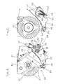
- the lower part of the conveying channel 26, which comprises the knife group and an adjusting device 28, is pivotable about an axis 29 and by means of a cylinder 31.
- a Cylinder 31 moves the pivotable part of the engagement position shown in Figure 1 in a disengaged position, whereupon extending in Figure 1 perpendicular to the plane of the figure Easy replacement of knife series.
- the knives can also over the open Tailgate of the winding chamber 3 are exchanged.
- the adjusting device 28 shown in more detail in Figure 2 is located on at least one side of the Delivery channel 26, the here of the side parts 32 of the upper and the pivotable side part 33 of the lower housing is hidden.
- the adjusting device 28 comprises in Figure 2 a cylinder 34, on the piston rod 36 a Rack 37 is attached.
- This rack 37 may not engage completely with two toothed gears 38 and 39, which in turn each a shift shaft 41st and 42 are assigned.
- leaf spring elements 43 in the gears 38 and 39 releasably engage, the rotation of the gears 38 and 39 and thus the rotation of the Switching shafts 41 and 42 are prevented, a gear 41 and / or a gear 42 should not with the rack 37 comb.
- the adjusting device 28 has a pressure accumulator 44.
- the pressure accumulator 44 fills this pressure accumulator 44 with a fluid when the cylinder in one or the other direction moves. So z. B. the knife groups by the method of the cylinder 34 in the Engagement position brought into the delivery channel 36, while, when the cylinder 34 is depressurized is switched, the accumulator 44 for the pivoting of the switching shafts 41, 42 in the Starting position is responsible.
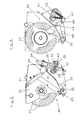
- FIG. 3 The cross-section shown in Figure 3 can be seen as a knife 46 of the knife row is pivoted into the conveying channel 26.
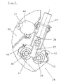
- a switching shaft 41 from the in Figure 3 shown position in the position shown in Figure 5
- the knife lever 47 to pivoted its pivot axis 48 and moves with its role 49 from that shown in Figure 3 Position along the edge 51 of the pivotable about the axis 30 knife to its Receiving trough 52.
- To pivot all successively arranged knife 46 a group of knives in the delivery channel 26th
- control of the adjusting device 28 by means of a control device from a region not directly on the conveyor channel 26 make out, for example, from the cab of a tractor of the harvester 1.
Landscapes
- Life Sciences & Earth Sciences (AREA)
- Environmental Sciences (AREA)
- Harvesting Machines For Specific Crops (AREA)
Applications Claiming Priority (2)
| Application Number | Priority Date | Filing Date | Title |
|---|---|---|---|
| DE200410023747 DE102004023747B4 (de) | 2004-05-11 | 2004-05-11 | Erntemaschine mit einer Aufnahmevorrichtung für landwirtschaftliches Erntegut |
| DE102004023747 | 2004-05-11 |
Publications (1)
| Publication Number | Publication Date |
|---|---|
| EP1595436A1 true EP1595436A1 (fr) | 2005-11-16 |
Family
ID=34936237
Family Applications (1)
| Application Number | Title | Priority Date | Filing Date |
|---|---|---|---|
| EP05009953A Withdrawn EP1595436A1 (fr) | 2004-05-11 | 2005-05-06 | Machine de récolte avec un dispositif de ramassage pour produits de récolte |
Country Status (2)
| Country | Link |
|---|---|
| EP (1) | EP1595436A1 (fr) |
| DE (1) | DE102004023747B4 (fr) |
Cited By (1)
| Publication number | Priority date | Publication date | Assignee | Title |
|---|---|---|---|---|
| US20230309456A1 (en) * | 2022-03-29 | 2023-10-05 | Cnh Industrial America Llc | Floating rotor and auger arrangement of agricultural baler |
Families Citing this family (2)
| Publication number | Priority date | Publication date | Assignee | Title |
|---|---|---|---|---|
| DE102007030635B4 (de) * | 2007-07-02 | 2009-07-02 | Maschinenfabrik Bernard Krone Gmbh | Erntemaschine mit Schneidwerk |
| DE102011013242B4 (de) | 2011-03-07 | 2023-07-27 | Pöttinger Landtechnik Gmbh | Ballenpresse |
Citations (4)
| Publication number | Priority date | Publication date | Assignee | Title |
|---|---|---|---|---|
| EP0077474A1 (fr) * | 1981-10-19 | 1983-04-27 | Klöckner-Humboldt-Deutz Aktiengesellschaft | Dispositif de coupe pour véhicule de récolte autochargeur |
| DE3213199C1 (de) * | 1982-04-08 | 1985-01-31 | Maschinenfabriken Bernard Krone Gmbh, 4441 Spelle | Ladewagen |
| DE4302199A1 (de) * | 1993-01-27 | 1994-07-28 | Claas Ohg | Schneidwerk für landwirtschaftliche Erntemaschinen |
| DE29712397U1 (de) | 1997-07-14 | 1997-09-25 | Maschinenfabriken Bernard Krone Gmbh, 48480 Spelle | Schneideinrichtung für landwirtschaftliche Erntemaschinen |
Family Cites Families (4)
| Publication number | Priority date | Publication date | Assignee | Title |
|---|---|---|---|---|
| DE19717542C2 (de) * | 1997-04-25 | 2002-09-19 | Lely Maschinenfabrik Gmbh | Schneidvorrichtung für landwirtschaftliche Erntemaschinen |
| DE19841598B4 (de) * | 1998-09-11 | 2008-04-10 | Welger Maschinenfabrik Gmbh | Fördervorrichtung für / an landwirtschaftliche(n) Erntefahrzeuge(n) |
| DE19905835C2 (de) * | 1999-02-12 | 2003-04-17 | Usines Claas France St Remy Wo | Hydraulische Stelleinrichtung |
| DE19928521A1 (de) * | 1999-06-22 | 2001-01-04 | Lely Welger Maschinenfabrik Gm | Zuführkanal für ein Erntefahrzeug, insbesondere für eine landwirtschaftliche Aufsammelballenpresse |
-
2004
- 2004-05-11 DE DE200410023747 patent/DE102004023747B4/de not_active Expired - Fee Related
-
2005
- 2005-05-06 EP EP05009953A patent/EP1595436A1/fr not_active Withdrawn
Patent Citations (4)
| Publication number | Priority date | Publication date | Assignee | Title |
|---|---|---|---|---|
| EP0077474A1 (fr) * | 1981-10-19 | 1983-04-27 | Klöckner-Humboldt-Deutz Aktiengesellschaft | Dispositif de coupe pour véhicule de récolte autochargeur |
| DE3213199C1 (de) * | 1982-04-08 | 1985-01-31 | Maschinenfabriken Bernard Krone Gmbh, 4441 Spelle | Ladewagen |
| DE4302199A1 (de) * | 1993-01-27 | 1994-07-28 | Claas Ohg | Schneidwerk für landwirtschaftliche Erntemaschinen |
| DE29712397U1 (de) | 1997-07-14 | 1997-09-25 | Maschinenfabriken Bernard Krone Gmbh, 48480 Spelle | Schneideinrichtung für landwirtschaftliche Erntemaschinen |
Cited By (2)
| Publication number | Priority date | Publication date | Assignee | Title |
|---|---|---|---|---|
| US20230309456A1 (en) * | 2022-03-29 | 2023-10-05 | Cnh Industrial America Llc | Floating rotor and auger arrangement of agricultural baler |
| US12453314B2 (en) * | 2022-03-29 | 2025-10-28 | Cnh Industrial America Llc | Floating rotor and auger arrangement of agricultural baler |
Also Published As
| Publication number | Publication date |
|---|---|
| DE102004023747B4 (de) | 2007-07-26 |
| DE102004023747A1 (de) | 2005-12-15 |
Similar Documents
| Publication | Publication Date | Title |
|---|---|---|
| EP2979535B1 (fr) | Dispositif de coupe pour moissonneuses agricoles | |
| EP2110014B1 (fr) | Dispositif de coupe pour récoltes agricoles en forme de tiges, doté d'un mécanisme destiné à la sélection de la longueur de coupe | |
| EP4108069B1 (fr) | Presse à balles rondes | |
| EP0077474B1 (fr) | Dispositif de coupe pour véhicule de récolte autochargeur | |
| EP1062860B1 (fr) | Dispositif pour vehicules de récolte, notamment pour presses à balles agricoles | |
| DE102015206845A1 (de) | Schneidwerk zur Ganzpflanzenernte | |
| DE102011013242B4 (de) | Ballenpresse | |
| DE102015218726A1 (de) | Strohhäcksler für einen Mähdrescher mit Gegenmessern und Reibleiste | |
| EP2742794B1 (fr) | Machine de récolte agricole et procédé de maintenance d'une telle machine de récolte | |
| AT394126B (de) | Schneidvorrichtung fuer halm- und/oder blattgut | |
| DE19534138C1 (de) | Ballenpresse für Erntegut | |
| EP0689760B1 (fr) | Dispositif de coupe pour véhicules de récolte | |
| EP3092890B1 (fr) | Barre de coupe de moissonneuse | |
| DE102004023747B4 (de) | Erntemaschine mit einer Aufnahmevorrichtung für landwirtschaftliches Erntegut | |
| EP2659763B1 (fr) | Machine de récolte dotée d'un dispositif de coupe | |
| EP3959961B1 (fr) | Presse pour produits de récolte à tiges pourvu de module de coupe amovible et procédé de manipulation d'un tel module de coupe amovible | |
| DE102005050172B4 (de) | Erntemaschine | |
| EP3981245A1 (fr) | Presse agricole pour fourrage et procédé de dépôt des balles de fourrage comprimé | |
| EP1932417B1 (fr) | Dispositif de saisie de récolte au sol | |
| DE4232989A1 (de) | Aufsammelkolbenpresse für landwirtschaftliches Erntegut | |
| DE3935767C2 (fr) | ||
| EP3721696B1 (fr) | Machine de récolte dotée d'un dispositif de coupe | |
| DE102004023760B4 (de) | Erntemaschine zum Aufnehmen von landwirtschaftlichem Erntegut | |
| DE102024103039A1 (de) | Maschine zum Mähen von stängelartigem Erntegut | |
| DE8130492U1 (de) | Schneidwerk für Selbstladeerntewagen |
Legal Events
| Date | Code | Title | Description |
|---|---|---|---|
| PUAI | Public reference made under article 153(3) epc to a published international application that has entered the european phase |
Free format text: ORIGINAL CODE: 0009012 |
|
| AK | Designated contracting states |
Kind code of ref document: A1 Designated state(s): AT BE BG CH CY CZ DE DK EE ES FI FR GB GR HU IE IS IT LI LT LU MC NL PL PT RO SE SI SK TR |
|
| AX | Request for extension of the european patent |
Extension state: AL BA HR LV MK YU |
|
| AKX | Designation fees paid | ||
| STAA | Information on the status of an ep patent application or granted ep patent |
Free format text: STATUS: THE APPLICATION IS DEEMED TO BE WITHDRAWN |
|
| 18D | Application deemed to be withdrawn |
Effective date: 20060517 |
|
| REG | Reference to a national code |
Ref country code: DE Ref legal event code: 8566 |